Page 825 of 4133
21 At a glance
Cockpit
Instrument cluster
Center console
Overhead control panel
Page 870 of 4133

66 Safety and SecurityOccupant safetyWarning!
G
USE SEAT BELTS PROPERLY�
Seat belts can only work when used
properly. Never wear seat belts in any
other way than as described in this sec-
tion, as that could result in serious inju-
ries in case of an accident.
�
Each occupant should wear their seat
belt at all times, because seat belts help
reduce the likelihood of and potential
severity of injuries in accidents, includ-
ing rollovers. The integrated restraint
system includes SRS (driver airbag,
front passenger airbag, front and rear
door mounted side impact airbags and
window curtain airbags), ETD (seat belt
emergency tensioning device for the
outboard passenger seats [except in the
optional third row seats]), and front seat
knee bolsters.
The system is designed to enhance the pro-
tection offered to properly belted occupants
in certain frontal (front airbags) and side
(side impact airbags and window curtain air-
bags) impacts which exceed preset deploy-
ment thresholds.�
Never wear the shoulder belt under your
arm, against your neck or off your shoul-
der. In a crash, your body would move
too far forward. That would increase the
chance of head and neck injuries. The
belt would also apply too much force to
the ribs or abdomen, which could se-
verely injure internal organs such as
your liver or spleen.
�
Never wear belts over rigid or breakable
objects in or on your clothing, such as
eyeglasses, pens, keys, etc., as these
might cause injuries.
�
Position the lap belt as low as possible
on your hips and not across the abdo-
men. If the belt is positioned across your
abdomen, it could cause serious injuries
in a crash.
�
Never use a seat belt for more than one
person at time. Do not fasten a seat belt
around a person and another person or
other objects.
�
Belts should not be worn twisted. In a
crash, you wouldn’t have the full width
of the belt to manage impact forces. The
twisted belt against your body could
cause injuries.
�
Pregnant women should also use a
lap-shoulder belt. The lap belt portion
should be positioned as low as possible
on the hips to avoid any possible pres-
sure on the abdomen.
�
Never place your feet on the instrument
panel or on the seat. Always keep both
feet on the floor in front of the seat.
Page 911 of 4133
107 Controls in detail
Lighting
�Lighting
For notes on how to switch on the head-
lamps (
�page 48) and use the turn signals
(
�page 49), see the “Getting started” sec-
tion.
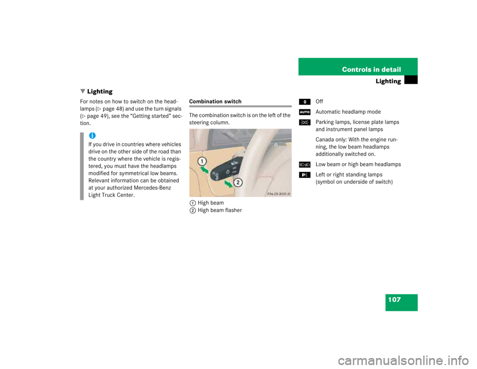
Combination switch
The combination switch is on the left of the
steering column.
1High beam
2High beam flasherMOff
UAutomatic headlamp mode
CParking lamps, license plate lamps
and instrument panel lamps
Canada only: With the engine run-
ning, the low beam headlamps
additionally switched on.
õLow beam or high beam headlamps
ƒLeft or right standing lamps
(symbol on underside of switch)
iIf you drive in countries where vehicles
drive on the other side of the road than
the country where the vehicle is regis-
tered, you must have the headlamps
modified for symmetrical low beams.
Relevant information can be obtained
at your authorized Mercedes-Benz
Light Truck Center.
Page 970 of 4133
166 Controls in detailUseful featuresOpening the storage compartment in
front of armrest�
Slide the cover3 rearward.
The storage compartment below con-
tains a cup holder (
�page 167).
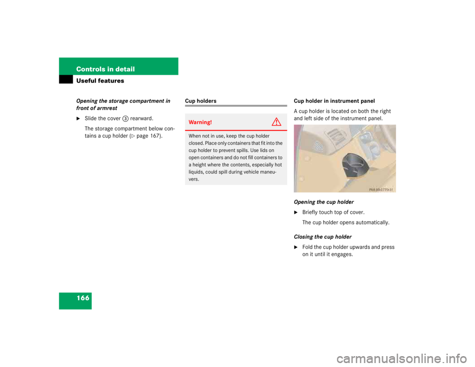
Cup holders Cup holder in instrument panel
A cup holder is located on both the right
and left side of the instrument panel.
Opening the cup holder
�
Briefly touch top of cover.
The cup holder opens automatically.
Closing the cup holder
�
Fold the cup holder upwards and press
on it until it engages.
Warning!
G
When not in use, keep the cup holder
closed. Place only containers that fit into the
cup holder to prevent spills. Use lids on
open containers and do not fill containers to
a height where the contents, especially hot
liquids, could spill during vehicle maneu-
vers.
Page 1126 of 4133

322 IndexCoolant 222, 304
Adding 223
Anticorrosion/antifreeze
quantity 304
Checking level 222
Indicator lamp 249
Temperature 213
Temperature gauge 117
Coolant level
Checking 215, 222
Crossing obstacles 204
Cruise control 150, 311
Canceling 151
Driving downhill 151
Driving uphill 151
Fine adjustment 152
LOW RANGE mode 152
Saving current speed 151
Setting speeds 152
Cruise control lever 150Cup holder 166
Cleaning 238
In front seat armrest 167
In instrument panel 166
In rear centerconsole 167
Customer Assistance Center (CAC) 311
D
Daytime running lamp mode 109
Deactivating
Air conditioning (cooling) 139
Air recirculation mode 139
Alarm 84
Anti-theft alarm system 84
Automatic climate control 135, 137
Cruise control 151
Defrost 138
Engine 54
ESP 81
Front fog lamps, rear fog lamp 111
Hazard warning flasher 112
Headlamps 54
Immobilizer 83
Rear passenger compartment ventila-
tion and climate control 141
Rear window defroster 133Residual heat 140
Seat heater* 98
Tow-away alarm 85
Tow-away alarm (vehicles with trip
computer*) 85
Tow-away alarm (vehicles without trip
computer*) 86
Deactivating automatic central
locking 93
Deep water see Standing water 200
Defogging
Windshield 138
Defrosting 138
Difficulties
While driving see Problems while
driving 51
With starting 47
Direction of rotation (tires) 227
Discharged battery
Jump starting 281
Disconnecting
Vehicle battery 279
Display in the speedometer 117
Page 1168 of 4133

AR68.30-P-4050GH
Removing and installing paneling on A-pillar
12.3.97
MODELS
163.113 /128 /136 /154 /157 /172 /174 /175
P68.30-0537-06
Vehicle illustrated up to 31.8.98
1
A-pillar paneling
2
Door rubber seal
3
Cover cap
4
Bolt
Remove/install
1
Remove door rubber seal (2) in area of A-pillar
2.1
Remove cap (3)
Up to 08/98.
3.1
Unscrew screw (4)Up to 08/98.
4
Remove A-pillar paneling (1)
The paneling is fastened in the instrument
panel at the bottom with lugs and will be
fastened with a clip at top as of 09/98.
Installation:
Replace clip
Long wedge
*115589035900
5
Install in the reverse order
On vehicles up to 08/98, on which a new
paneling should be installed, the upper area
of the fixing opening at the top of the A-pillar
must be enlarged so that the clip retainer of
the paneling can be installed in the A-pillar.
Long wedge
115 589 03 59 00
Copyright DaimlerChrysler AG 09.05.2006 CD-Ausgabe G/10/04 . This WIS print-out will not be recorde
d by Modification services.
Page 1
Page 1499 of 4133

NOTES ON NAVIGATION SYSTEM TRAFFICSTAR - AH82.61-P-0001-03A
Models 129, 140, 163, 168, 170, 202, 208, 210
Customer information on GPS antenna installation location
On all sedans and coupes, the GPS antenna can be mounted on the rear shelf as an alternative to the instrument
panel.
TrafficStar customer information
The TrafficStar navigation system is available in two versions from the Becker Company:
1. Mat black cover
2. Precious wood cover, burr walnut (Avant-
garde)
conversion for Tele Aid
emergency call system
Notes regarding the Tele-Aid
emergency call systemMODEL 463 ...AH82.95-P-0001-
01GA
Notes regarding the Tele-Aid
emergency call systemMODEL 199AH82.95-P-0001-
01SLR
Notes on Tele Aid
emergency call system
control module changeMODEL 140 with CODE
(348) TELE AID
emergency call systemAH82.95-P-0001-02A
Cleaning plastic cover plates
of lampsMODEL 168, 169, 171,
199, 203, 204, 208, 209,
210, 211, 215, 216, 219,
220, 221, 230, 240, 245.2AH82.10-P-1002-01A
Cleaning plastic cover plates
of lampsMODEL 454.0AH82.10-P-1002-
01FF
Notes on installation of
wiring harnesses in roof areaMODEL 203.0AH82.25-P-1000-01P
Notes on avoiding damage to
fiber optic cables during
repair workMODEL 164, 169, 211,
216, 221, 245, 251, 454 ...AH82.60-P-0001-
05AK
Notes on avoiding damage to
fiber optic cables during
repair workMODEL 219.3 with Media
Oriented System Transport
(MOST)AH82.60-P-0001-
05TX
Notes on fiber optic cableMODEL 129, 163, 168,
170, 202, 203, 208, 209,
210, 215, 220, 230, 414,
463 ...AH82.70-P-0001-02A
2001 Mercedes-Benz ML320
1998-2005 ACCESSORIES & BODY, CAB Electrical System - Body - 163 Chassis
me
Saturday, October 02, 2010 3:30:04 PMPage 4 © 2006 Mitchell Repair Information Company, LLC.
Page 1751 of 4133
MODELS 163.154 /172 /113 with CODE (612b) Xenon headlamp unit
MODELS 163.174/175/128/157
Fig. 157: Identifying Headlight Beam Adjustment Control Module
Remove/Install
1Remove cover below
instrument panel (left) AR68.10-P-1500GH
2Disconnect connector
from headlamp range
adjustment control module
(N71)
3Unscrew headlamp range
adjustment control module
from mount of extended
activity module (EAM) 2 nuts.
4Remove headlamp range
adjustment control module
(N71)
5Install in the reverse order
6Adjust headlamp into zero
position using STAR
DIAGNOSIS
2001 Mercedes-Benz ML320
1998-2005 ACCESSORIES & BODY, CAB Electrical System - Body - 163 Chassis
me
Saturday, October 02, 2010 3:30:08 PMPage 256 © 2006 Mitchell Repair Information Company, LLC.

 Xenon headlamp unit
MODELS 163.174/175/128/157
Fig. 157: Identifying Headlight Beam Adjustment Control Module
Remove/Install
1Remove cover below
inst")