Page 1938 of 4133
Fig. 396: Identifying D-Network Cell Phone Components
Removal
1Disconnect ground cable
of battery
AR54.10-P-0003A
2Remove radio
3Remove stowage
compartment below radio
4Remove stowage
compartment in center
armrest
5Remove wooden cover
from shift lever
6Remove cover below
right instrument panel
7Remove A-pillar paneling
at top right
8Tie out D-net antenna
lead Tied back in radio
shaft.
Install
9Install holder on
telephone console AZ82.70-P-0001-01A
10Installing hands free AZ82.70-P-0001-02A
2001 Mercedes-Benz ML320
1998-2005 ACCESSORIES & BODY, CAB Electrical System - Body - 163 Chassis
me
Saturday, October 02, 2010 3:30:14 PMPage 443 © 2006 Mitchell Repair Information Company, LLC.
Page 1940 of 4133
Fig. 397: Identifying D-Network Cell Phone Components
Removal
1Disconnect ground cable
of battery
AR54.10-P-0003A
2Remove radio
3Remove stowage
compartment below radio
4Remove stowage
compartment in center
armrest
5Remove wooden cover
from shift lever
6Remove cover below
instrument panel on right
7Remove automatic A/C
control panel
8Remove A-pillar paneling
at top right
9Tie out D-network
antenna lead Tied back in radio
shaft.
Installation
10Install holder on AZ82.70-P-0001-01A
2001 Mercedes-Benz ML320
1998-2005 ACCESSORIES & BODY, CAB Electrical System - Body - 163 Chassis
me
Saturday, October 02, 2010 3:30:14 PMPage 445 © 2006 Mitchell Repair Information Company, LLC.
Page 1945 of 4133
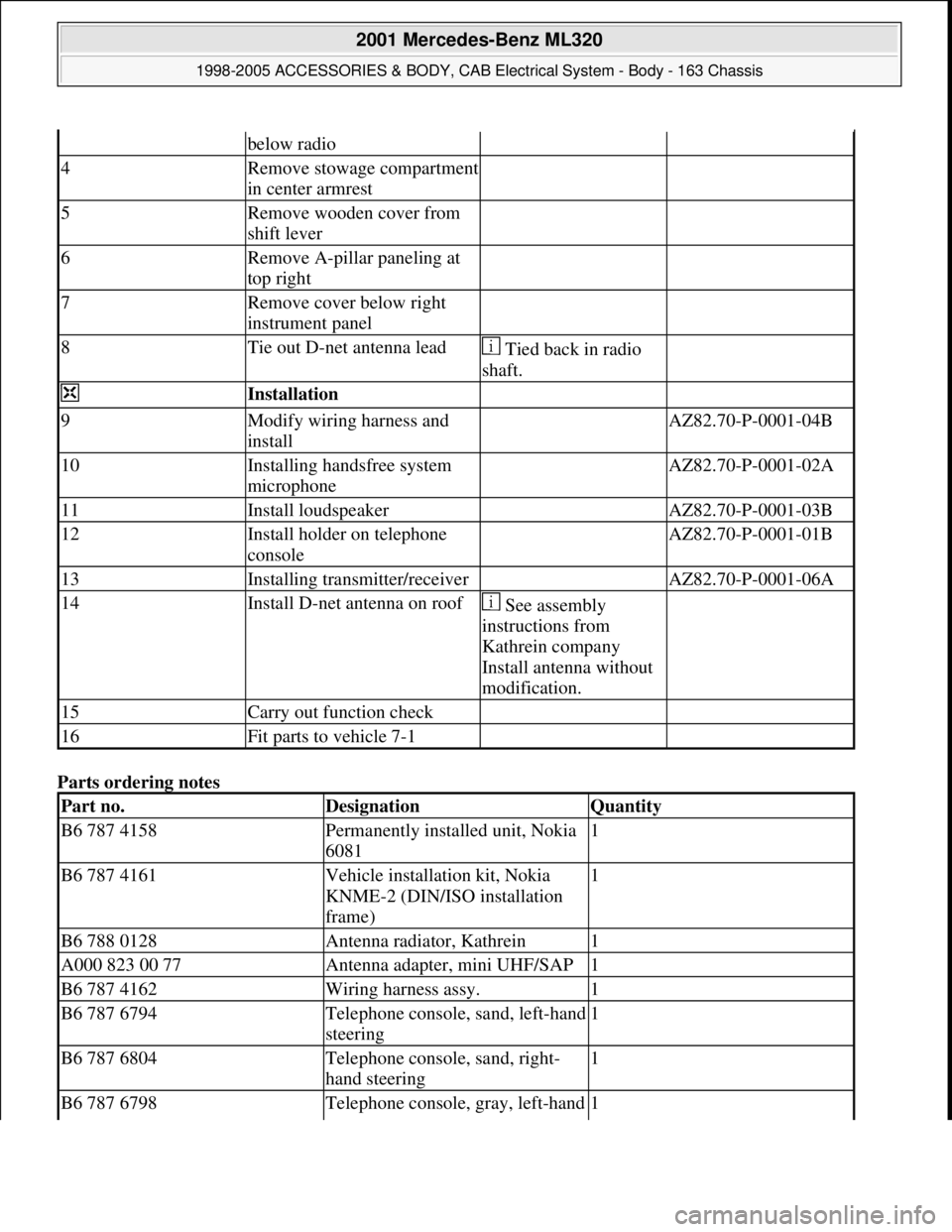
Parts ordering notes
below radio
4Remove stowage compartment
in center armrest
5Remove wooden cover from
shift lever
6Remove A-pillar paneling at
top right
7Remove cover below right
instrument panel
8Tie out D-net antenna lead Tied back in radio
shaft.
Installation
9Modify wiring harness and
install AZ82.70-P-0001-04B
10Installing handsfree system
microphone AZ82.70-P-0001-02A
11Install loudspeaker AZ82.70-P-0001-03B
12Install holder on telephone
console AZ82.70-P-0001-01B
13Installing transmitter/receiver AZ82.70-P-0001-06A
14Install D-net antenna on roof See assembly
instructions from
Kathrein company
Install antenna without
modification.
15Carry out function check
16Fit parts to vehicle 7-1
Part no.DesignationQuantity
B6 787 4158Permanently installed unit, Nokia
60811
B6 787 4161Vehicle installation kit, Nokia
KNME-2 (DIN/ISO installation
frame)1
B6 788 0128Antenna radiator, Kathrein1
A000 823 00 77Antenna adapter, mini UHF/SAP1
B6 787 4162Wiring harness assy.1
B6 787 6794Telephone console, sand, left-hand
steering1
B6 787 6804Telephone console, sand, right-
hand steering1
B6 787 6798Telephone console, gray, left-hand 1
2001 Mercedes-Benz ML320
1998-2005 ACCESSORIES & BODY, CAB Electrical System - Body - 163 Chassis
me
Saturday, October 02, 2010 3:30:14 PMPage 450 © 2006 Mitchell Repair Information Company, LLC.
Page 1947 of 4133
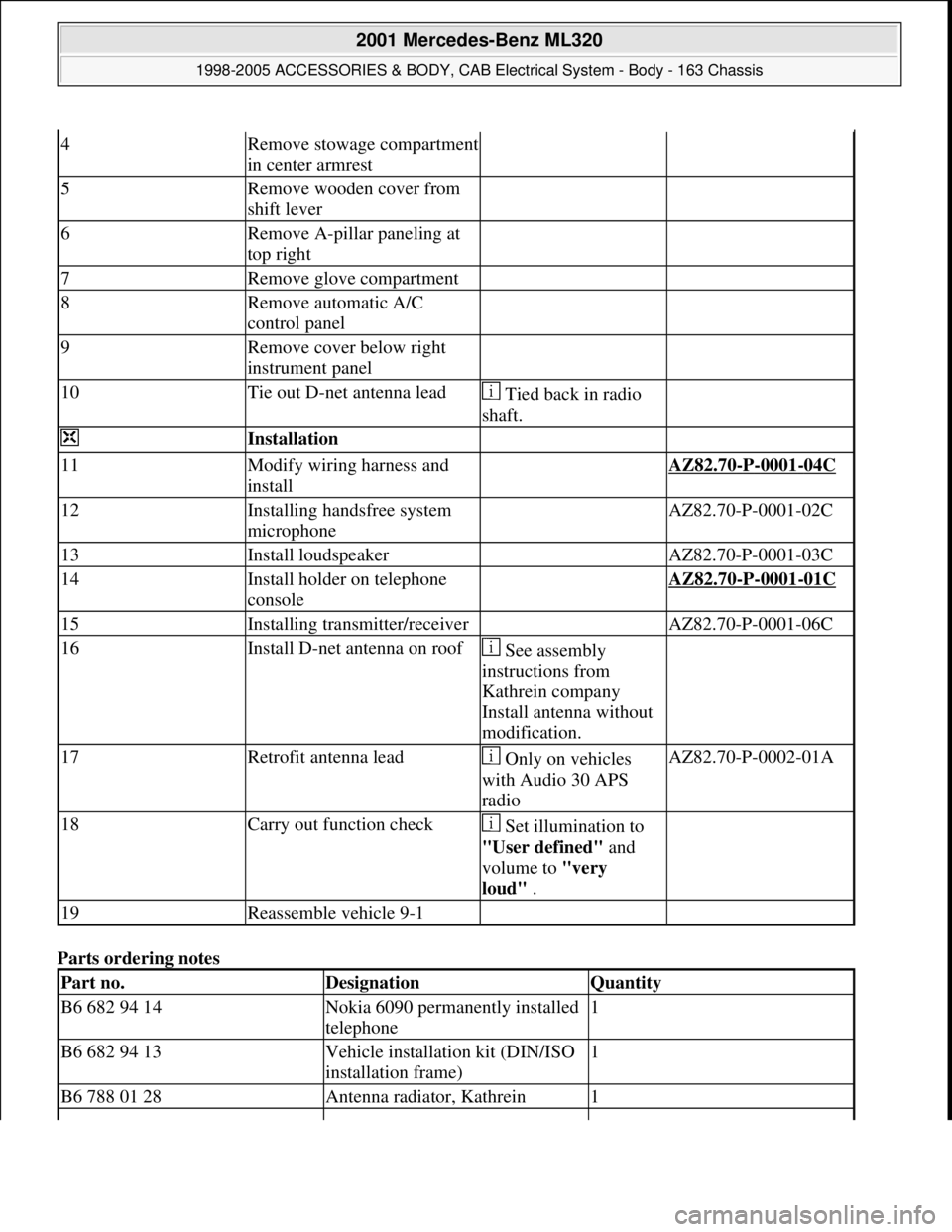
Parts ordering notes
4Remove stowage compartment
in center armrest
5Remove wooden cover from
shift lever
6Remove A-pillar paneling at
top right
7Remove glove compartment
8Remove automatic A/C
control panel
9Remove cover below right
instrument panel
10Tie out D-net antenna lead Tied back in radio
shaft.
Installation
11Modify wiring harness and
install AZ82.70-P-0001-04C
12Installing handsfree system
microphone AZ82.70-P-0001-02C
13Install loudspeaker AZ82.70-P-0001-03C
14Install holder on telephone
console AZ82.70-P-0001-01C
15Installing transmitter/receiver AZ82.70-P-0001-06C
16Install D-net antenna on roof See assembly
instructions from
Kathrein company
Install antenna without
modification.
17Retrofit antenna lead Only on vehicles
with Audio 30 APS
radioAZ82.70-P-0002-01A
18Carry out function check Set illumination to
"User defined" and
volume to "very
loud" .
19Reassemble vehicle 9-1
Part no.DesignationQuantity
B6 682 94 14Nokia 6090 permanently installed
telephone1
B6 682 94 13Vehicle installation kit (DIN/ISO
installation frame)1
B6 788 01 28Antenna radiator, Kathrein1
2001 Mercedes-Benz ML320
1998-2005 ACCESSORIES & BODY, CAB Electrical System - Body - 163 Chassis
me
Saturday, October 02, 2010 3:30:14 PMPage 452 © 2006 Mitchell Repair Information Company, LLC.
Page 1952 of 4133
Fig. 403: Identifying Connector, Connection Line & Interface
5. Apply special glue to rear of microphone (arrow) and glue hands-free system microphone (B25) included
in installation kit to headliner.
Align microphone so that pickup opening points towards driver.
Fig. 404: Locating Rear Of Microphone & Hands
-Free System Microphone (B25)
6. Glue microphone lead behind headliner as shown in figure and along right A-pillar below instrument
panel to radio shaft.
7. Connect all control and operation modules and connect battery for checking proper function of telephone.
Avoid error messa
ges from unconnected control modules.
2001 Mercedes-Benz ML320
1998-2005 ACCESSORIES & BODY, CAB Electrical System - Body - 163 Chassis
me
Saturday, October 02, 2010 3:30:14 PMPage 457 © 2006 Mitchell Repair Information Company, LLC.
Page 2035 of 4133
2001-04 STARTING & CHARGING SYSTEMS
Generators & Regulators - 163 Chassis
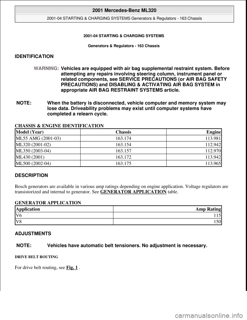
IDENTIFICATION
CHASSIS & ENGINE IDENTIFICATION
DESCRIPTION
Bosch generators are available in various amp ratings depending on engine application. Voltage regulators are
transistorized and internal to generator. See GENERATOR APPLICATION
table.
GENERATOR APPLICATION
ADJUSTMENTS
DRIVE BELT ROUTING
For drive belt routing, see Fig. 1 . WARNING:Vehicles are equipped with air bag supplemental restraint system. Before
attempting any repairs involving steering column, instrument panel or
related components, see SERVICE PRECAUTIONS (or AIR BAG SAFETY
PRECAUTIONS) and DISABLING & ACTIVATING AIR BAG SYSTEM in
appropriate AIR BAG RESTRAINT SYSTEMS article.
NOTE: When the battery is disconnected, vehicle computer and memory system may
lose data. Driveability problems may exist until computer systems have
completed a relearn cycle.
Model (Year)ChassisEngine
ML55 AMG (2001-03)163.174113.981
ML320 (2001-02)163.154112.942
ML350 (2003-04)163.157112.970
ML430 (2001)163.172113.942
ML500 (2002-04)163.175113.965
ApplicationAmp Rating
V6115
V8150
NOTE: Vehicles have automatic belt tensioners. No adjustment is necessary.
2001 Mercedes-Benz ML320
2001-04 STARTING & CHARGING SYSTEMS Generators & Regulators - 163 Chassis
2001 Mercedes-Benz ML320
2001-04 STARTING & CHARGING SYSTEMS Generators & Regulators - 163 Chassis
me
Saturday, October 02, 2010 3:20:31 PMPage 1 © 2006 Mitchell Repair Information Company, LLC.
me
Saturday, October 02, 2010 3:20:35 PMPage 1 © 2006 Mitchell Repair Information Company, LLC.
Page 2042 of 4133

3. Normalize side power windows. See NORMALIZING POWER WINDOWS .
4. Start engine and run at idle. Turn steering wheel from one lock position to the other to activate steering
angle sensor. Center steering wheel. Message "EI. STAB. PROGRAM GO TO GARAGE" should erase
from multifunction display panel.
5. If equipped, normalize tilting/sliding roof. See NORMALIZING TILTING/SLIDING ROOF
.
6. If equipped, normalize memory power seats, steering column and outside mirror if components are
installed. See NORMALIZING MEMORY POWER SEATS, STEERING COLUMN & OUTSIDE
MIRROR .
Normalizing Power Windows
1. Completely close each window with manual switch. Hold switch in closed position for .3 second.
2. Repeat procedure for each power window.
Normalizing Memory Power Seats, Steering Column & Outside Mirror
1. Using manual switch, move seat to each end position and hold for .3 second. Repeat procedure for each
switch except rear stop of backrest.
2. Repeat procedure for end positions of steering wheel and outside mirrors.
Normalizing Tilting/Sliding Roof
Open roof with SR switch until mechanical stop is reached. Continue to press switch for .5 seconds.
Setting Time
1. Use bottom left button on steering wheel to scroll through menus on instrument cluster to "Settings"
menu.
2. Move selection marker with + or - button to "Time" submenu.
3. Press up or down arrows to "Clock, hours" setting. Confirm selection marker is on the hour setting.
4. Press + or - to set hour. Press reset knob in instrument cluster to confirm.
5. Move selection marker with + or - button to "Time" submenu.
6. Press up or down arrows to "Clock, minutes" setting. Confirm selection marker is on the minutes setting.
7. Press + or - to set minute. Press reset knob in instrument cluster to confirm.
TESTING
If generator malfunctions, check for Diagnostic Trouble Codes (DTCs) in Motor Electronics Sequential Fuel
Injection (ME-SFI) system. See appropriate SELF-DIAGNOSTICS article in ENGINE PERFORMANCE. If
cause of generator malfunction is not engine performance related, replace generator.
RETRIEVING & ERASING DIAGNOSTIC TROUBLE CODES
NOTE: Before replacing any component that scan tool suggests are faulty, ensure that
all wiring connections and harness connectors are okay. Ensure that power and
2001 Mercedes-Benz ML320
2001-04 STARTING & CHARGING SYSTEMS Generators & Regulators - 163 Chassis
me
Saturday, October 02, 2010 3:20:32 PMPage 8 © 2006 Mitchell Repair Information Company, LLC.
Page 2511 of 4133
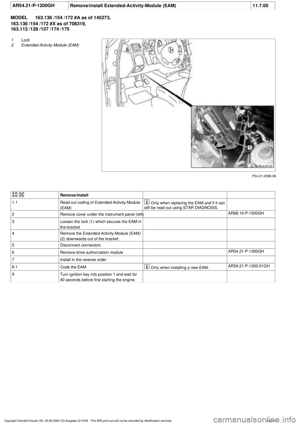
AR54.21-P-1200GH
Remove/install Extended-Activity-Module (EAM)
11.7.00
MODEL
163.136 /154 /172 #A as of 145273,
163.136 /154 /172 #X as of 708319,
163.113 /128 /157 /174 /175
P54.21-2098-06
1
Lock
2
Extended-Activity-Module (EAM)
Remove/install
1.1
Read out coding of Extended-Activity-Module
(EAM)
Only
when replacing the EAM and if it can
still be read out using STAR DIAGNOSIS.
2
Remove cover under the instrument panel (left)
AR68.10-P-1500GH
3
Loosen the lock (1) which secures the EAM in
the bracket
4
Remove the Extended-Activity-Module (EAM)
(2) downwards out of the bracket
5
Disconnect connectors
6
Remove drive authorization module
AR54.21-P-1300GH
7
Install in the reverse order
8.1
Code the EAM
Only
when installing a new EAM.
AR54.21-P-1200-01GH
9
Turn ignition key into position 1 and wait for
40 seconds before first starting the engine.
Copyright DaimlerChrysler AG 05.06.2006 CD-Ausgabe G/10/04 . This WIS print-out will not be recorde
d by Modification services.
Page 1