Page 3288 of 4133
Model 163 up to 31.8.01
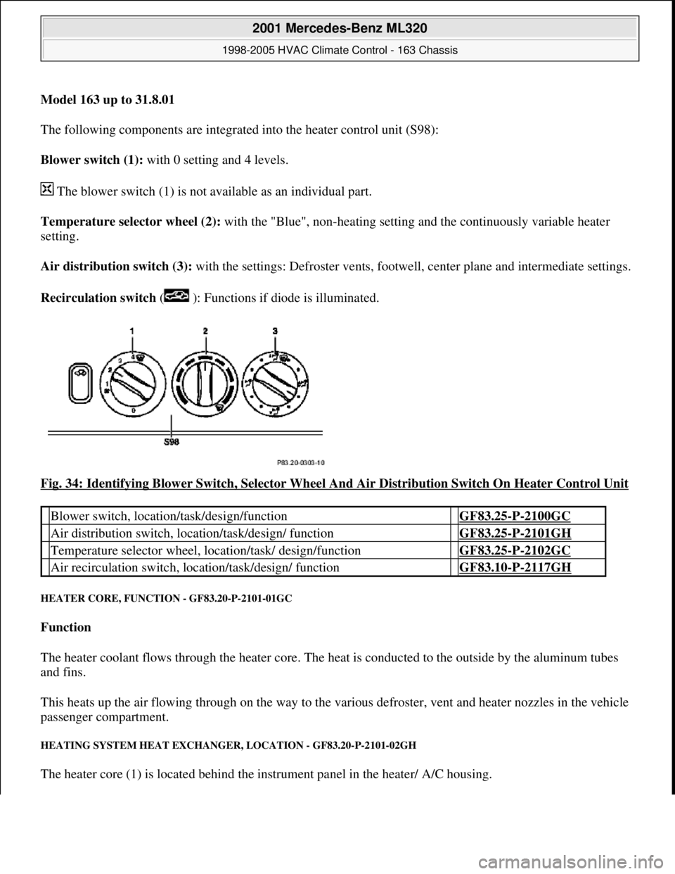
The following components are integrated into the heater control unit (S98):
Blower switch (1): with 0 setting and 4 levels.
The blower switch (1) is not available as an individual part.
Temperature selector wheel (2): with the "Blue", non-heating setting and the continuously variable heater
setting.
Air distribution switch (3): with the settings: Defroster vents, footwe ll, center plane and intermediate settings.
Recirculation switch ( ): Functions if diode is illuminated.
Fig. 34: Identifying Blower Switch, Selector Wheel And Air Distribution Switch On Heater Control Unit
HEATER CORE, FUNCTI ON - GF83.20-P-2101-01GC
Function
The heater coolant flows through the heater core. The he at is conducted to the outside by the aluminum tubes
and fins.
This heats up the air flowing through on the way to the vari ous defroster, vent and heater nozzles in the vehicle
passenger compartment.
HEATING SYSTEM HEAT EXCHANGE R, LOCATION - GF83.20-P-2101-02GH
The heater core (1) is located behind the instrument panel in the heater/ A/C housing.
Blower switch, location/task/design/function GF83.25-P-2100GC
Air distribution switch, locat ion/task/design/ function GF83.25-P-2101GH
Temperature selector wheel, location/task/ design/function GF83.25-P-2102GC
Air recirculation switch, loca tion/task/design/ function GF83.10-P-2117GH
2001 Mercedes-Benz ML320
1998-2005 HVAC Climate Control - 163 Chassis
me
Saturday, October 02, 2010 3:23:15 PMPage 44 © 2006 Mitchell Repair Information Company, LLC.
Page 3290 of 4133
The heating water circulation pump runs in any event 1 minute after starting residual engine heat operation. The
overshoot conditions at least will be fulfilled.
Overshoot conditions
Coolant temperature 100°C --> overshoot time 5 minutes
Coolant temperature >100°C --> overshoot time 10 minutes
HEATER HOUSING POSITION - GF83.20-P-2103-01GH
The heater housing (1) is located beneath the instrument panel.
Fig. 36: Identifying Heater Housing
HEATER BOX FUNCTION - GF83.20-P-2103-02GH
Operating condition: Heating
2001 Mercedes-Benz ML320
1998-2005 HVAC Climate Control - 163 Chassis
me
Saturday, October 02, 2010 3:23:15 PMPage 46 © 2006 Mitchell Repair Information Company, LLC.
Page 3296 of 4133
HEATER HOUSING POSITION/TASK/FUNCTION - GF83.20-P-2110GC
MODEL 163 up to 31.8.01
168 up to except CODE (580) Air conditioning or Tempmatic for USA
Shown on model 168 as of 1.03.01
Fig. 42: Identifying Heater Housing
- Shown On Model 168 As Of 1.03.01
FRESH AIR/RECIRCULATED AIR FLAP, LOCATION/PURPOSE/FUNCTION - GF83.20-P-2111GC
MODEL 163, 168
Heating water
circulation pump
function
GF83.20-P-
2102-01GI
Heater housing
positionThe heater housing (1) is located beneath the instrument
panel.
Model 168 up to 28.02.01GF83.20-P-2103-
01GC
Model 163GF83.20-P-2103-
01GH
Heater housing task GF83.20-P-2103-
03GC
Heater housing
functionModel 168GF83.20-P-2103-
02GC
Model 163GF83.20-P-2103-
02GH
2001 Mercedes-Benz ML320
1998-2005 HVAC Climate Control - 163 Chassis
me
Saturday, October 02, 2010 3:23:15 PMPage 52 © 2006 Mitchell Repair Information Company, LLC.
Page 3312 of 4133
Fig. 58: Identifying AC Button On Air Conditioning Control Module
AC BUTTON, LOCATION/TASK/FUNCTION - GF83.30-P-2103GH
MODEL 163 up to 31.8.01 with CODE (580) Air conditioning or Tempmatic for USA
EVAPORATOR HOUSING, POSITION - GF83.30-P-2104-01GH
The evaporator housing (1) is located below the instrument panel.
Fig. 59: Identifying Evaporator Housing
EVAPORATOR HOUSING, FUNCTION - GF83.30-P-2104-02GH
AC button,
location GF83.30-P-2103-
02GH
AC button, taskThe AC button is used to switch the air conditioning system on
and off.
AC button,
function GF83.30-P-2103-
01GH
2001 Mercedes-Benz ML320
1998-2005 HVAC Climate Control - 163 Chassis
me
Saturday, October 02, 2010 3:23:15 PMPage 68 © 2006 Mitchell Repair Information Company, LLC.
Page 3339 of 4133
Blending air flap actuator
Fresh air/recirculated air flap actuator
Defroster vent flap actuator motor
Rear shutoff flap actuator motor
Footwell flap actuator
Electric heater booster (for engine 612.963 only) and therefore forms a complete unit.
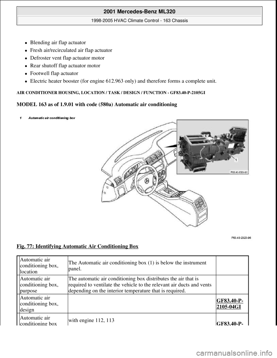
AIR CONDITIONER HOUSING, LOCATION / TASK / DESIGN / FUNCTION - GF83.40-P-2105GI
MODEL 163 as of 1.9.01 with code (580a) Automatic air conditioning
Fig. 77: Identifying Automatic Air Conditioning Box
Automatic air
conditioning box,
locationThe Automatic air conditioning box (1) is below the instrument
panel.
Automatic air
conditioning box,
purposeThe automatic air conditioning box distributes the air that is
required to ventilate the vehicle to the relevant air ducts and vents
depending on the interior temperature that is required.
Automatic air
conditioning box,
design
GF83.40-P-
2105-04GI
Automatic air
conditioning box with engine 112, 113GF83.40-P-
2001 Mercedes-Benz ML320
1998-2005 HVAC Climate Control - 163 Chassis
me
Saturday, October 02, 2010 3:23:16 PMPage 95 © 2006 Mitchell Repair Information Company, LLC.
Page 3385 of 4133
The in-car temperature sensor (B10/4) is equipped with an aspirator blower which constantly draws air out of
the vehicle interior for the temperature measurement when the ignition is ON . The in-car temperature sensor
(B10/4) records the interior temperature and conveys it to the AAC push-button control module. A comparison
is made there with the setting on the temperature selector and the blend air flap is repositioned depending on the
result of this comparison.
It is connected to the AAC push-button control module via a separate electric cable.
Constant circulation of the interior air at the in-car temperature sensor (B10/4) is achieved by the in-car
temperature sensor aspirator blower (M9) and therefore ensures a high level of control accuracy.
In contrast to the previous suction jet nozzle a high level of control accuracy is ensured by the in-car
temperature sensor aspirator blower (M9).
OUTSIDE AIR TEMPERATURE SENSOR FUNCTION - GF83.57-P-2103-01GH
Function
The resistance of the outside air temperature sensor (B10/5) depends on the ambient temperature and the ground
speed. With an increase in the outside temperature, its resistance decreases. This information is sent to the air
conditioning control module (N19). This information causes a slight lowering or raising of the temperature
selected at the air conditioning control panel.
This achieves an adaptation to the temperature perception of the occupants.
The outside temperature depends on the ground speed, which prevents a value for the outside temperature that is
too high - as may occur when the vehicle is stationary or when traveling slowly, e.g. due to thermal radiation
from the engine - from being sent to the air conditioning control module (N19).
The value of the ground speed is sent from the traction systems control module (N47) via the instrument cluster
(A1) to the air conditioning control module (N19).
When switching the ignition off and on and with speeds lower than 20 km/h the temperature measured last is
used.
OUTSIDE AIR TEMPERATURE SENSOR POSITION - GF83.57-P-2103-02GH
The outside air temperature sensor (B10/5) is located at the front on the air inlet of the evaporator housing.
2001 Mercedes-Benz ML320
1998-2005 HVAC Climate Control - 163 Chassis
me
Saturday, October 02, 2010 3:23:17 PMPage 141 © 2006 Mitchell Repair Information Company, LLC.
Page 3389 of 4133
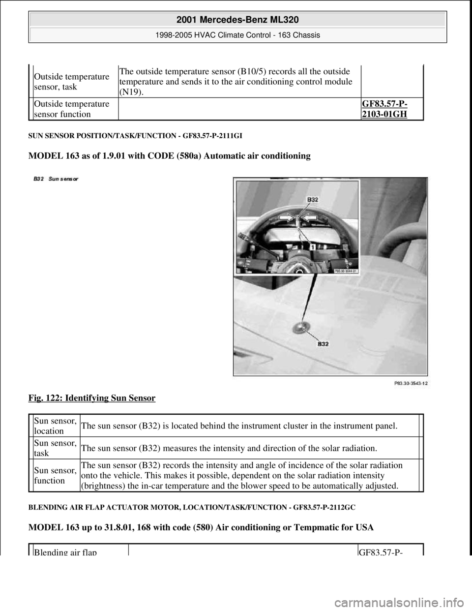
SUN SENSOR POSITION/TASK/FUNCTION - GF83.57-P-2111GI
MODEL 163 as of 1.9.01 with CODE (580a) Automatic air conditioning
Fig. 122: Identifying Sun Sensor
BLENDING AIR FLAP ACTUATOR MOTOR, LOCATION/TASK/FUNCTION - GF83.57-P-2112GC
MODEL 163 up to 31.8.01, 168 with code (580) Air conditioning or Tempmatic for USA
Outside temperature
sensor, taskThe outside temperature sensor (B10/5) records all the outside
temperature and sends it to the air conditioning control module
(N19).
Outside temperature
sensor function GF83.57-P-
2103-01GH
Sun sensor,
locationThe sun sensor (B32) is located behind the instrument cluster in the instrument panel.
Sun sensor,
taskThe sun sensor (B32) measures the intensity and direction of the solar radiation.
Sun sensor,
functionThe sun sensor (B32) records the intensity and angle of incidence of the solar radiation
onto the vehicle. This makes it possible, dependent on the solar radiation intensity
(brightness) the in-car temperature and the blower speed to be automatically adjusted.
Blending air flap GF83.57-P-
2001 Mercedes-Benz ML320
1998-2005 HVAC Climate Control - 163 Chassis
me
Saturday, October 02, 2010 3:23:17 PMPage 145 © 2006 Mitchell Repair Information Company, LLC.
Page 3393 of 4133
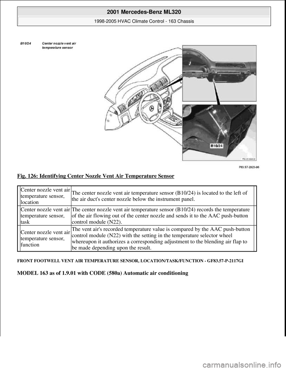
Fig. 126: Identifying Center Nozzle Vent Air Temperature Sensor
FRONT FOOTWELL VENT AIR TEMPERATURE SENSOR, LOCATION/TASK/FUNCTION - GF83.57-P-2117GI
MODEL 163 as of 1.9.01 with CODE (580a) Automatic air conditioning
Center nozzle vent air
temperature sensor,
locationThe center nozzle vent air temperature sensor (B10/24) is located to the left of
the air duct's center nozzle below the instrument panel.
Center nozzle vent air
temperature sensor,
taskThe center nozzle vent air temperature sensor (B10/24) records the temperature
of the air flowing out of the center nozzle and sends it to the AAC push-button
control module (N22).
Center nozzle vent air
temperature sensor,
functionThe vent air's recorded temperature value is compared by the AAC push-button
control module (N22) with the setting in the temperature selector wheel
whereupon it authorizes a corresponding adjustment to the blending air flap to
be made depending upon the result.
2001 Mercedes-Benz ML320
1998-2005 HVAC Climate Control - 163 Chassis
me
Saturday, October 02, 2010 3:23:17 PMPage 149 © 2006 Mitchell Repair Information Company, LLC.