Page 3474 of 4133
Fig. 186: Identifying External Torx Set (001 589 76 09 00)
MAINTENANCE
REPLACE DUST FILTER FOR HEATIN G/AIR CONDITIONING - AP83.00-P-8381GH
MODEL 163.113 /128 /136 /154 /157 /172 /174 /175
Fig. 187: Identifying Dust Filter
BF83.55-P-1008-
01AAdditional oil filling
capacity when
replacing refrigerant
compressorCompressor oilcm3 20
Specifications for
Operating FluidsSheetBB00.40-P-0362-
00A
Remove/install
1Remove cover below instrument
panel (passenger side) Up to 31.08.99AR68.10-P-
1520GH
Remove/install cover below
instrument panel (right) As of 01.09.99AR68.10-P-
1520GI
2First unlatch retaining clamp (3), then
remove cover(2)
3Withdraw dust filter (1) downwards
(arrows) The dust filter must not be
cleaned; it must be replaced.
4Install in the reverse order
2001 Mercedes-Benz ML320
1998-2005 HVAC Climate Control - 163 Chassis
me
Saturday, October 02, 2010 3:23:19 PMPage 230 © 2006 Mitchell Repair Information Company, LLC.
Page 3493 of 4133
AR54.30-P-6015GH
Remove instrument cluster
20.1.97
MODEL
163.113 /128 /136 /154 /157 /172 /174 /175
P54.25-2680-06
Steering wheel removed for clarity
3
Upper steering column cover
12
Side covering
P54.30-0630-06
Steering wheel removed for clarity
4
Clips
5
Frames
6
Hook
7
Lug
8
Mount
9
Screw
10
Spreading clips
11
Connector
13
Mount
A1
Instrument cluster
Remove, Install
1
Disconnect ground cable of battery
To prevent unintended contact, insulate
the ground lead cable lug.
AR54.10-P-0003A
2
Unlock steering wheel and move to its lowest
position
See Operating Instructions
3
Remove upper steering column cover (3)
Risk of fracturing! Do not scratch the
steering wheel.
Only as of VIN A145273, X708319:
Loosen clips on the side and front. Gently
squeeze the cover together and pull out
between the steering wheel and instrument
panel.
Copyright DaimlerChrysler AG 09.05.2006 CD-Ausgabe G/10/04 . This WIS print-out will not be recorde
d by Modification services.
Page 1
Page 3494 of 4133

4
Remove side covers (12)
Danger of breaking retaining lugs. Do not
damage instrument panel.
Up to VIN A145272, X708318:
3 covers:
Remove side covers first. Detach center
cover from instrument panel and rotate so
that the retaining lugs point upwards. Then
pull out to the right.
As of VIN A145273, X708319:
2 covers: First
remove the right cover, then the left. It is not
necessary to detach the connectors. The
covers can remain attached to the wiring
harness.
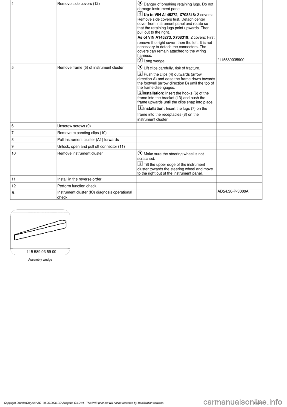
Long wedge
*115589035900
5
Remove frame (5) of instrument cluster
Lift clips carefully, risk of fracture.
Push the clips (4) outwards (arrow
direction A) and ease the frame down towards
the footwell (arrow direction B) until the top of
the frame disengages.
Installation:
Insert the hooks (6) of the
frame into the bracket (13) and push the
frame upwards until the clips snap into place.
Installation:
Insert the lugs (7) on the
frame into the receptacles (8) on the
instrument cluster.
6
Unscrew screws (9)
7
Remove expanding clips (10)
8
Pull instrument cluster (A1) forwards
9
Unlock, open and pull off connector (11)
10
Remove instrument cluster
Make sure the steering wheel is not
scratched.
Tilt the upper edge of the instrument
cluster towards the steering wheel and move
to the right out of the instrument panel.
11
Install in the reverse order
12
Perform function check
a
Instrument cluster (IC) diagnosis operational
check
AD54.30-P-3000A
Assembly wedge
115 589 03 59 00
Copyright DaimlerChrysler AG 09.05.2006 CD-Ausgabe G/10/04 . This WIS print-out will not be recorde
d by Modification services.
Page 2
Page 3499 of 4133

AR68.10-P-1040GH
Remove/install bottom section of instrument panel
13.3.97
MODELS
163.113 /128 /136 /154 /157 /172 /174 /175
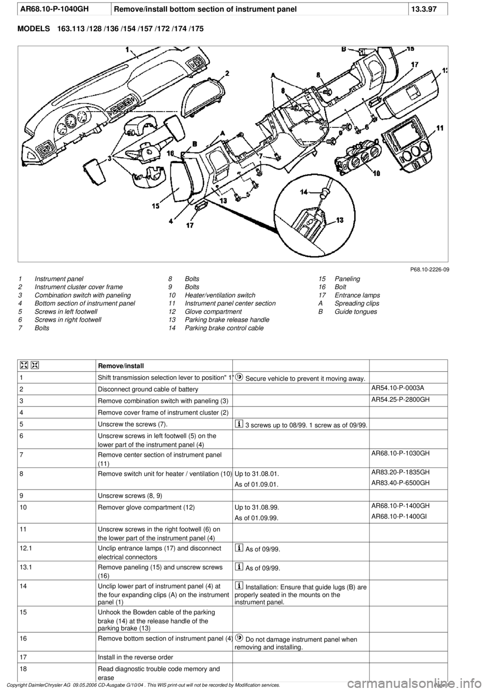
P68.10-2226-09
1
Instrument panel
2
Instrument cluster cover frame
3
Combination switch with paneling
4
Bottom section of instrument panel
5
Screws in left footwell
6
Screws in right footwell
7
Bolts
15
Paneling
16
Bolt
17
Entrance lamps
A
Spreading clips
B
Guide tongues
8
Bolts
9
Bolts
10
Heater/ventilation switch
11
Instrument panel center section
12
Glove compartment
13
Parking brake release handle
14
Parking brake control cable
Remove/install
1
Shift transmission selection lever to position" 1"
Secure vehicle to prevent it moving away.
2
Disconnect ground cable of battery
AR54.10-P-0003A
3
Remove combination switch with paneling (3)
AR54.25-P-2800GH
4
Remove cover frame of instrument cluster (2)
5
Unscrew the screws (7).
3 screws up to 08/99. 1 screw as of 09/99.
6
Unscrew screws in left footwell (5) on the
lower part of the instrument panel (4)
7
Remove center section of instrument panel
(11)
AR68.10-P-1030GH
8
Remove switch unit for heater / ventilation (10)
Up to 31.08.01.
AR83.20-P-1835GH
As of 01.09.01.
AR83.40-P-6500GH
9
Unscrew screws (8, 9)
10
Remover glove compartment (12)
Up to 31.08.99.
AR68.10-P-1400GH
As of 01.09.99.
AR68.10-P-1400GI
11
Unscrew screws in the right footwell (6) on
the lower part of the instrument panel (4)
12.1
Unclip entrance lamps (17) and disconnect
electrical connectors
As of 09/99.
13.1
Remove paneling (15) and unscrew screws
(16)
As of 09/99.
14
Unclip lower part of instrument panel (4) at
the four expanding clips (A) on the instrument
panel (1)
Installation: Ensure that guide lugs (B) are
properly seated in the mounts on the
instrument panel.
15
Unhook the Bowden cable of the parking
brake (14) at the release handle of the
parking brake (13)
16
Remove bottom section of instrument panel (4)
Do not damage instrument panel when
removing and installing.
17
Install in the reverse order
18
Read diagnostic trouble code memory and
erase
Copyright DaimlerChrysler AG 09.05.2006 CD-Ausgabe G/10/04 . This WIS print-out will not be recorde
d by Modification services.
Page 1
Page 3501 of 4133

AR68.10-P-1030GH
Remove/install center section of instrument panel
11.4.97
MODEL
163.113 /128 /136 /154 /157 /172 /174 /175
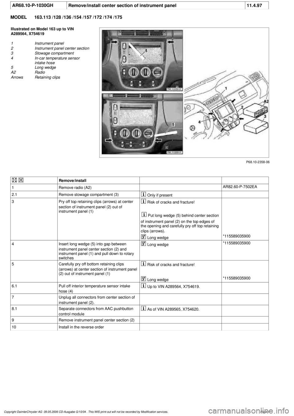
P68.10-2358-06
Illustrated on Model 163 up to VIN
A289564, X754619
1
Instrument panel
2
Instrument panel center section
3
Stowage compartment
4
In-car temperature sensor
intake hose
5
Long wedge
A2
Radio
Arrows
Retaining clips
Remove/install
1
Remove radio (A2)
AR82.60-P-7502EA
2.1
Remove stowage compartment (3)
Only if present
3
Pry off top retaining clips (arrows) at center
section of instrument panel (2) out of
instrument panel (1)
Risk of cracks and fracture!
Put long wedge (5) behind center section
of instrument panel (2) on the top edges of
the opening and carefully pry off top retaining
clips (arrows).
Long wedge
*115589035900
4
Insert long wedge (5) into gap between
instrument panel center section (2) and
instrument panel (1) and pull down to rotary
switches
Long wedge
*115589035900
5
Carefully pry off bottom retaining clips
(arrows) at center section of instrument panel
(2) out of instrument panel (1)
Risk of cracks and fracture!
Long wedge
*115589035900
6.1
Pull off interior temperature sensor intake
hose (4)
Up to VIN A289564, X754619.
7
Unplug all connectors from center section of
instrument panel (2).
8.1
Separate connectors from AAC pushbutton
control module
As of VIN A289565, X754620.
9
Remove instrument panel center section (2)
10
Install in the reverse order
Copyright DaimlerChrysler AG 09.05.2006 CD-Ausgabe G/10/04 . This WIS print-out will not be recorde
d by Modification services.
Page 1
Page 3505 of 4133
AR68.10-P-1500GH
Removing and installing cover below instrument panel (left)
4.2.97
MODELS
163.113 /128 /136 /154 /157 /172 /174 /175
P68.10-0522-06
1
Plugs
2
Bolt
3
Clips
4
Cover
X11/4
Datalink connector
Remove/install
1
Remove plug (1)
2 each.
2
Unscrew screw (2)
2 each.
Installation:
Observe clips (3).
3
Unlock and remove data link connector (X11/4)
4
Take off cover (4)
5
Install in the reverse order
Copyright DaimlerChrysler AG 09.05.2006 CD-Ausgabe G/10/04 . This WIS print-out will not be recorde
d by Modification services.
Page 1
Page 3506 of 4133
AR68.10-P-1520GH
Remove/install cover below instrument panel (right)
4.2.97
MODEL
163.136 /154 /172 #A up to 145272,
163.136 /154 /172 #X up to 708318
P68.10-0527-06
1
Cover
2
Plug-in clips
3
Catch
X58/1
Interior socket
Remove/Install
1
Unhook catch (3) on blower motor
Risk of breakage!
2
Unclip cover (1)
Cover is fastened with 2 clips (2).
3
Disconnect electrical connector from interior
socket (X58/1)
4
Install in the reverse order
Copyright DaimlerChrysler AG 09.05.2006 CD-Ausgabe G/10/04 . This WIS print-out will not be recorde
d by Modification services.
Page 1
Page 3507 of 4133
AR68.10-P-1520GI
Remove/install cover below instrument panel (right)
2.6.99
MODEL
163.136 /154 /172 #A as of 145273,
163.136 /154 /172 #X as of 708319,
163.113 /128 /157 /174 /175
P68.10-2249-06
1
Torx bolts
2
Cover
3
Locking lever
X58/1
I
nterior socket
Remove/Install
1
Unscrew Torx screws (1) form cover (2)
2
Fold locking lever (3) downward
3
Pull cover (2) downward and lay down
4
Disconnect electrical connector from interior
socket (X58/1)
5
Install in the reverse order
Copyright DaimlerChrysler AG 09.05.2006 CD-Ausgabe G/10/04 . This WIS print-out will not be recorde
d by Modification services.
Page 1