Page 3508 of 4133
AR83.40-P-6500GH
Remove/install switch unit/automatic air conditioning control module
7.3.01
MODEL
163.113 /154 /174 #A as of 289565,
163.113 #X as of 754620,
163.128 /157 /175
P83.40-2329-06
1
Instrument panel center section
2
Bolts
N22
AAC pushbutton control module
Remove/install
1
Remove center section of instrument panel
AR68.10-P-1030GH
2
Remove switch unit of AAC control and
operating module (N22) from center part of
instrument panel (1)
3
Unscrew screws (2) from AAC control and
operating module (N22)
4
Disconnect AAC control and operating
module (N22) from center section of
instrument panel
Loosen retaining clamps at the top and
bottom.
5
Install in the reverse order
Copyright DaimlerChrysler AG 09.05.2006 CD-Ausgabe G/10/04 . This WIS print-out will not be recorde
d by Modification services.
Page 1
Page 3509 of 4133
AR83.20-P-1835GH
Remove, install switch unit for heater/ventilation
30.4.97
MODELS
163.113/136/154/172/174 up to 31.8.01 with CODE (580) air conditioning or Tempmatic for USA
P83.20-0262-06
1
Center part of instrument panel
2
Defroster cable
3
Footwell ventilation cable
4
Pushbutton control module
X72/3
Connector
Remove/install
1
Remove radio
AR82.60-P-7502EA
2
Remove center part of instrument panel (1)
AR68.10-P-1030GH
3
Unscrew bolts at heater/AC controls (4) and
remove controls
4
Detach cable (2, 3)
Unclip cables at heater/AC controls.
5
Disconnect connector (X72/3) at heater/AC
controls (4)
6
Install in the reverse order
Copyright DaimlerChrysler AG 09.05.2006 CD-Ausgabe G/10/04 . This WIS print-out will not be recorde
d by Modification services.
Page 1
Page 3510 of 4133

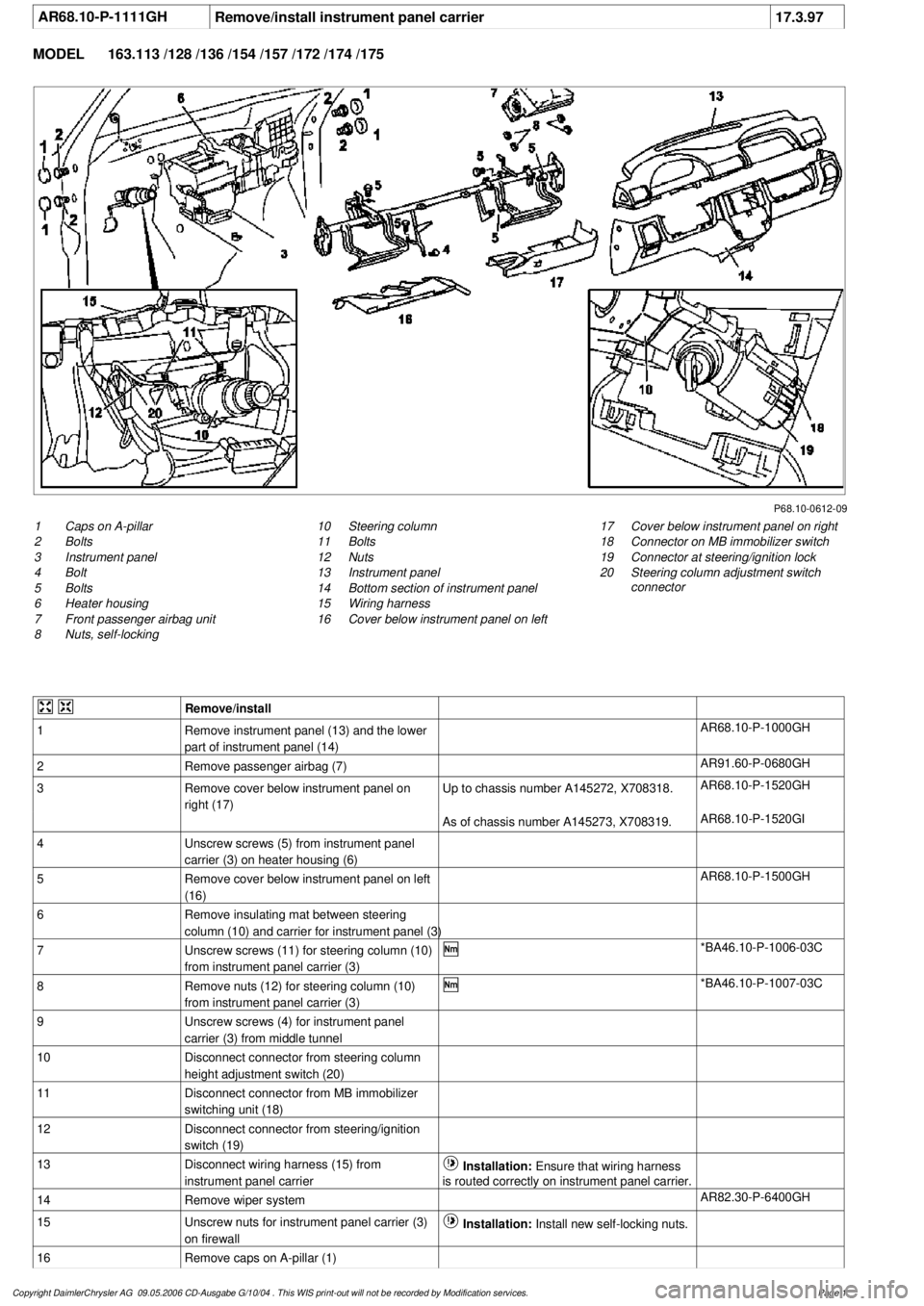
AR68.10-P-1111GH
Remove/install instrument panel carrier
17.3.97
MODEL
163.113 /128 /136 /154 /157 /172 /174 /175
P68.10-0612-09
1
Caps on A-pillar
2
Bolts
3
Instrument panel
4
Bolt
5
Bolts
6
Heater housing
7
Front passenger airbag unit
8
Nuts, self-locking
17
Cover below instrument panel on right
18
Connector on MB immobilizer switch
19
Connector at steering/ignition lock
20
Steering column adjustment switch
connector
10
Steering column
11
Bolts
12
Nuts
13
Instrument panel
14
Bottom section of instrument panel
15
Wiring harness
16
Cover below instrument panel on left
Remove/install
1
Remove instrument panel (13) and the lower
part of instrument panel (14)
AR68.10-P-1000GH
2
Remove passenger airbag (7)
AR91.60-P-0680GH
3
Remove cover below instrument panel on
right (17)
Up to chassis number A145272, X708318.
AR68.10-P-1520GH
As of chassis number A145273, X708319.
AR68.10-P-1520GI
4
Unscrew screws (5) from instrument panel
carrier (3) on heater housing (6)
5
Remove cover below instrument panel on left
(16)
AR68.10-P-1500GH
6
Remove insulating mat between steering
column (10) and carrier for instrument panel (3)
7
Unscrew screws (11) for steering column (10)
from instrument panel carrier (3)
*BA46.10-P-1006-03C
8
Remove nuts (12) for steering column (10)
from instrument panel carrier (3)
*BA46.10-P-1007-03C
9
Unscrew screws (4) for instrument panel
carrier (3) from middle tunnel
10
Disconnect connector from steering column
height adjustment switch (20)
11
Disconnect connector from MB immobilizer
switching unit (18)
12
Disconnect connector from steering/ignition
switch (19)
13
Disconnect wiring harness (15) from
instrument panel carrier
Installation:
Ensure that wiring harness
is routed correctly on instrument panel carrier.
14
Remove wiper system
AR82.30-P-6400GH
15
Unscrew nuts for instrument panel carrier (3)
on firewall
Installation:
Install new self-locking nuts.
16
Remove caps on A-pillar (1)
Copyright DaimlerChrysler AG 09.05.2006 CD-Ausgabe G/10/04 . This WIS print-out will not be recorde
d by Modification services.
Page 1
Page 3511 of 4133
17
Unscrew screws (2) for instrument panel
carrier (3) from A-pillar
18
Remove instrument panel carrier (3) and take
out of passenger compartment to side
through passenger door
Be careful not to damage center console
when removing and installing.
19
Install in the reverse order
Jacket tube
Number
Designation
MODEL
Series 163
BA46.10-P-1006-03C
Screw for jacket tube on upper instrument
panel carrier
Nm
20
BA46.10-P-1007-03C
Jacket tube collar nut on instrument panel
carrier at bottom
Nm
18
Copyright DaimlerChrysler AG 09.05.2006 CD-Ausgabe G/10/04 . This WIS print-out will not be recorde
d by Modification services.
Page 2
Page 3512 of 4133
AR54.65-P-0003GH
Removing and installing Parktronic system (PTS) warning display in instrument
panel
23.4.01
MODEL
163.113 /128 /154 /157 /174 /175 with CODE (220a) Parktronic System (PTS)
P54.65-2414-11
1
Connector
A44/4
PTS warning display, center of instrument panel
Remove/install
1
Remove PTS warning display (center of
dashboard)A44/4) above the instrument panel.
Ensure that the instrument panel is not
damaged.
Long wedge
*115589035900
2
Disconnect connector (1).
3
Install in the reverse order
Long wedge
115 589 03 59 00
Copyright DaimlerChrysler AG 09.05.2006 CD-Ausgabe G/10/04 . This WIS print-out will not be recorde
d by Modification services.
Page 1
Page 3513 of 4133

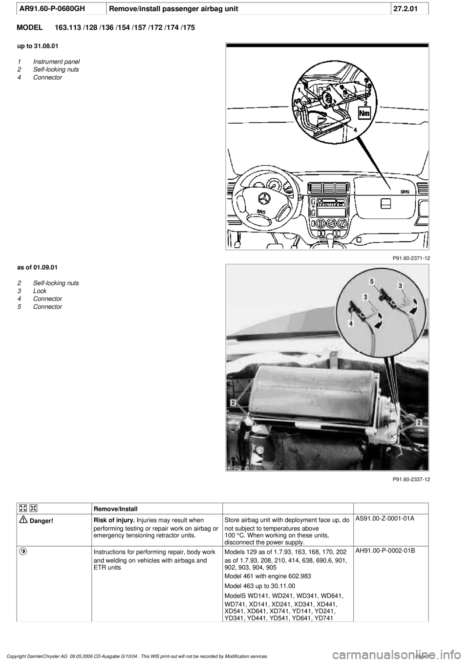
AR91.60-P-0680GH
Remove/install passenger airbag unit
27.2.01
MODEL
163.113 /128 /136 /154 /157 /172 /174 /175
P91.60-2371-12
up to 31.08.01
1
Instrument panel
2
Self-locking nuts
4
Connector
P91.60-2337-12
as of 01.09.01
2
Self-locking nuts
3
Lock
4
Connector
5
Connector
Remove/Install
Danger!
Risk of injury.
Injuries may result when
performing testing or repair work on airbag or
emergency tensioning retractor units.
Store airbag unit with deployment face up, do
not subject to temperatures above
100 °C. When working on these units,
disconnect the power supply.
AS91.00-Z-0001-01A
Instructions for performing repair, body work
and welding on vehicles with airbags and
ETR units
Models 129 as of 1.7.93, 163, 168, 170, 202
as of 1.7.93, 208, 210, 414, 638, 690.6, 901,
902, 903, 904, 905
Model 461 with engine 602.983
Model 463 up to 30.11.00
ModelS WD141, WD241, WD341, WD641,
WD741, XD141, XD241, XD341, XD441,
XD541, XD641, XD741, YD141, YD241,
YD341, YD441, YD541, YD641, YD741
AH91.00-P-0002-01B
Copyright DaimlerChrysler AG 09.05.2006 CD-Ausgabe G/10/04 . This WIS print-out will not be recorde
d by Modification services.
Page 1
Page 3514 of 4133

Legal regulations on handling and storing
airbags and emergency tensioning retractors
Models 124, 129, 140, 163, 168, 170, 202,
203, 208, 209, 210, 211.004/ 006/ 016/ 061/
065/ 070, 215, 220, 230, 314, 316, 318, 414,
461, 463, 638, 668, 670, 690.6, 901, 902,
903, 904, 905, 950, 952, 953, 954, 970, 972,
974, 975, 976
Model WD141, WD241, WD341, WD641,
WD741, XD141, XD241, XD341, XD441,
XD541, XD641, XD741, YD141, YD241,
YD341, YD441, YD541, YD641, YD741
AH91.00-P-0004-01A
o
Notes on disposing of airbag and emergency
tensioning retractor units
All models
OS91.00-P-0001-01A
1
Disconnect ground cable of battery
To prevent unintended contact, insulate
the ground lead cable lug.
AR54.10-P-0003A
2
Remove instrument panel
AR68.10-P-1000GH
3.1
Open lock (3) on both plugs (4, 5)
As of 01.09.01.
4
Detach plugs (4, 5) from squib
Up to 31.8.01, only one plug (4) is present.
Installation:
Plug/s must audibly latch.
As of 01.09.01: Close lock (3) on plugs after
latching.
5
Slacken self-locking nuts (2) from the front
passenger airbag
*BA91.60-P-1003-01A
6
Remove front passenger airbag
7.1
Render airbag units unusable
Only if airbag unit is replaced.
AR91.60-P-0611A
8
Install in the reverse order
9
Carry out diagnosis
a
Airbag (AB) electrical system test
up to 30.11.99.
AD91.60-P-6000GH
As of 1.12.99: Perform diagnosis with
STAR DIAGNOSIS.
Airbag
Number
Designation
Model
163
BA91.60-P-1003-01A
Nut of front passenger airbag unit to
instrument panel mounting
Nm
8
Copyright DaimlerChrysler AG 09.05.2006 CD-Ausgabe G/10/04 . This WIS print-out will not be recorde
d by Modification services.
Page 2
Page 3515 of 4133

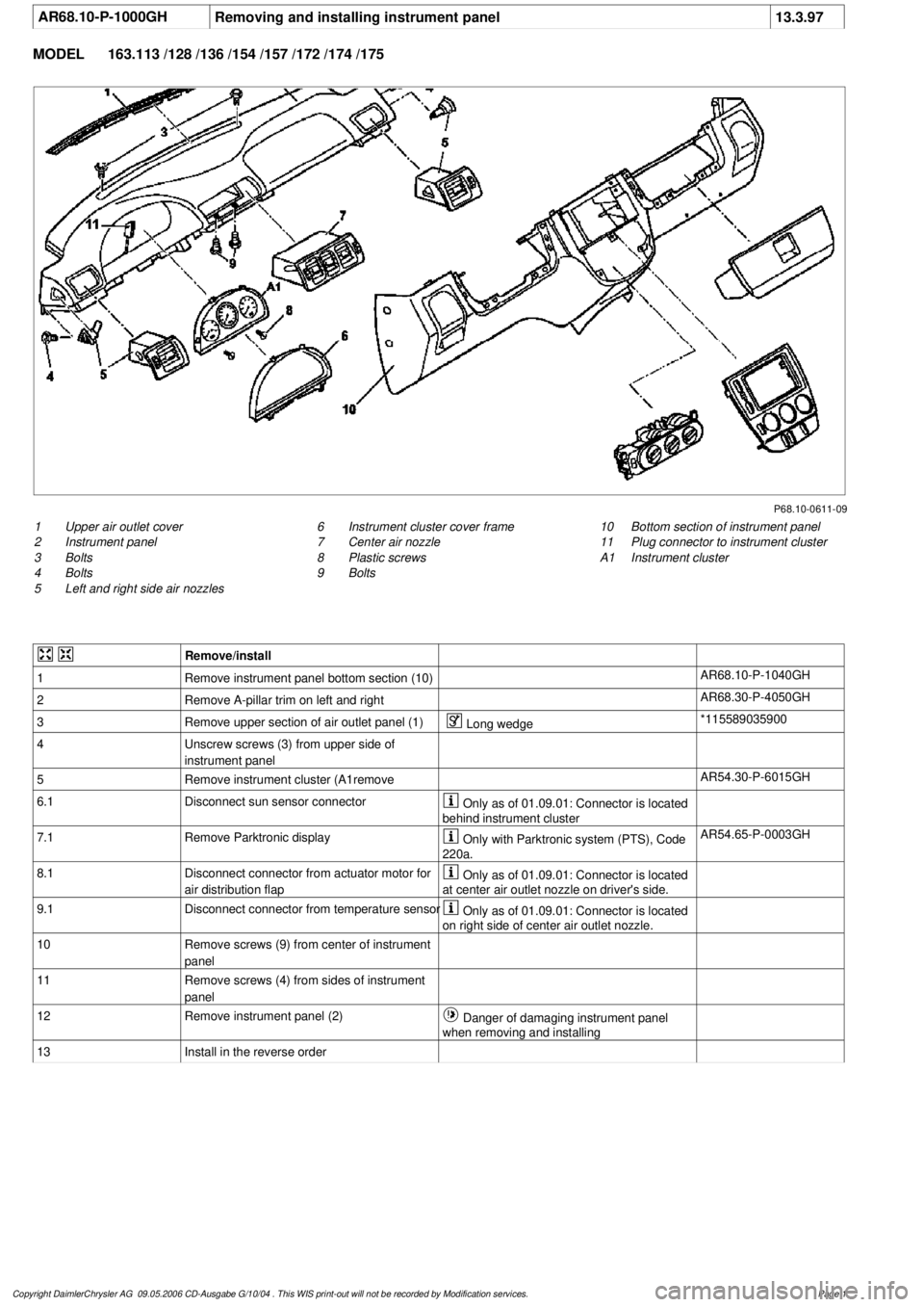
AR68.10-P-1000GH
Removing and installing instrument panel
13.3.97
MODEL
163.113 /128 /136 /154 /157 /172 /174 /175
P68.10-0611-09
1
Upper air outlet cover
2
Instrument panel
3
Bolts
4
Bolts
5
Left and right side air nozzles
10
Bottom section of instrument panel
11
Plug connector to instrument cluster
A1
Instrument cluster
6
Instrument cluster cover frame
7
Center air nozzle
8
Plastic screws
9
Bolts
Remove/install
1
Remove instrument panel bottom section (10)
AR68.10-P-1040GH
2
Remove A-pillar trim on left and right
AR68.30-P-4050GH
3
Remove upper section of air outlet panel (1)
Long wedge
*115589035900
4
Unscrew screws (3) from upper side of
instrument panel
5
Remove instrument cluster (A1remove
AR54.30-P-6015GH
6.1
Disconnect sun sensor connector
Only as of 01.09.01: Connector is located
behind instrument cluster
7.1
Remove Parktronic display
Only with Parktronic system (PTS), Code
220a.
AR54.65-P-0003GH
8.1
Disconnect connector from actuator motor for
air distribution flap
Only as of 01.09.01: Connector is located
at center air outlet nozzle on driver's side.
9.1
Disconnect connector from temperature sensor
Only as of 01.09.01: Connector is located
on right side of center air outlet nozzle.
10
Remove screws (9) from center of instrument
panel
11
Remove screws (4) from sides of instrument
panel
12
Remove instrument panel (2)
Danger of damaging instrument panel
when removing and installing
13
Install in the reverse order
Copyright DaimlerChrysler AG 09.05.2006 CD-Ausgabe G/10/04 . This WIS print-out will not be recorde
d by Modification services.
Page 1