1997 MERCEDES-BENZ ML430 instrument panel
[x] Cancel search: instrument panelPage 2845 of 4133
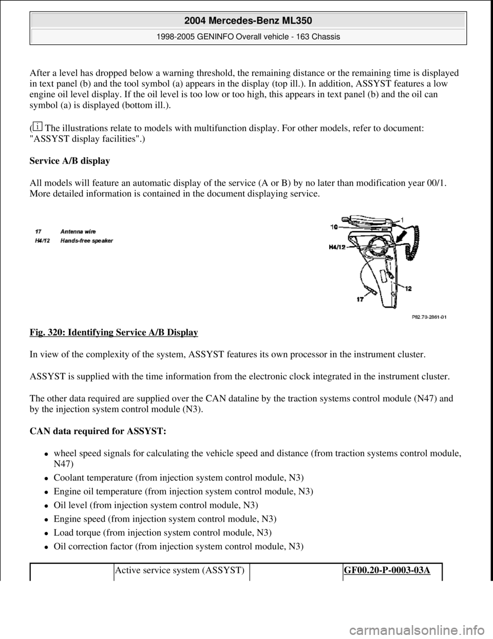
After a level has dropped below a warning threshold, the remaining distance or the remaining time is displayed
in text panel (b) and the tool symbol (a) appears in the display (top ill.). In addition, ASSYST features a low
engine oil level display. If the oil level is too low or too high, this appears in text panel (b) and the oil can
symbol (a) is displayed (bottom ill.).
( The illustrations relate to models with multifunction display. For other models, refer to document:
"ASSYST display facilities".)
Service A/B display
All models will feature an automatic display of the service (A or B) by no later than modification year 00/1.
More detailed information is contained in the document displaying service.
Fig. 320: Identifying Service A/B Display
In view of the complexity of the system, ASSYST features its own processor in the instrument cluster.
ASSYST is supplied with the time information from the electronic clock integrated in the instrument cluster.
The other data required are supplied over the CAN dataline by the traction systems control module (N47) and
by the injection system control module (N3).
CAN data required for ASSYST:
wheel speed signals for calculating the vehicle speed and distance (from traction systems control module,
N47)
Coolant temperature (from injection system control module, N3)
Engine oil temperature (from injection system control module, N3)
Oil level (from injection system control module, N3)
Engine speed (from injection system control module, N3)
Load torque (from injection system control module, N3)
Oil correction factor (from injection system control module, N3)
Active service system (ASSYST) GF00.20-P-0003-03A
2004 Mercedes-Benz ML350
1998-2005 GENINFO Overall vehicle - 163 Chassis
me
Saturday, October 02, 2010 3:47:47 PMPage 200 © 2006 Mitchell Repair Information Company, LLC.
Page 3178 of 4133
AR68.10-P-1400GI
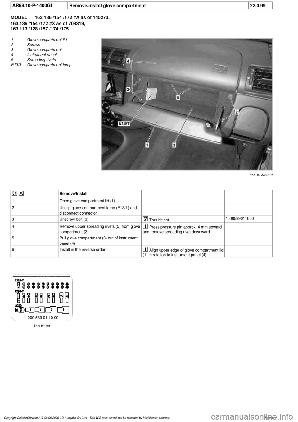
Remove/install glove compartment
22.4.99
MODEL
163.136 /154 /172 #A as of 145273,
163.136 /154 /172 #X as of 708319,
163.113 /128 /157 /174 /175
P68.10-2330-06
1
Glove compartment lid
2
Screws
3
Glove compartment
4
Instrument panel
5
Spreading rivets
E13/1
Glove compartment lamp
Remove/Install
1
Open glove compartment lid (1)
2
Unclip glove compartment lamp (E13/1) and
disconnect connector
3
Unscrew bolt (2)
Torx bit set
*000589011000
4
Remove upper spreading rivets (5) from glove
compartment (3)
Press pressure pin approx. 4 mm upward
and remove spreading rivet downward.
5
Pull glove compartment (3) out of instrument
panel (4)
6
Install in the reverse order
Align upper edge of glove compartment lid
(1) in relation to instrument panel (4).
Torx bit set
000 589 01 10 00
Copyright DaimlerChrysler AG 09.05.2006 CD-Ausgabe G/10/04 . This WIS print-out will not be recorde
d by Modification services.
Page 1
Page 3179 of 4133
AR68.10-P-1300GH
Adjust glove compartment lid
4.2.97
MODEL
163.136 /154 /172 #A up to 145272
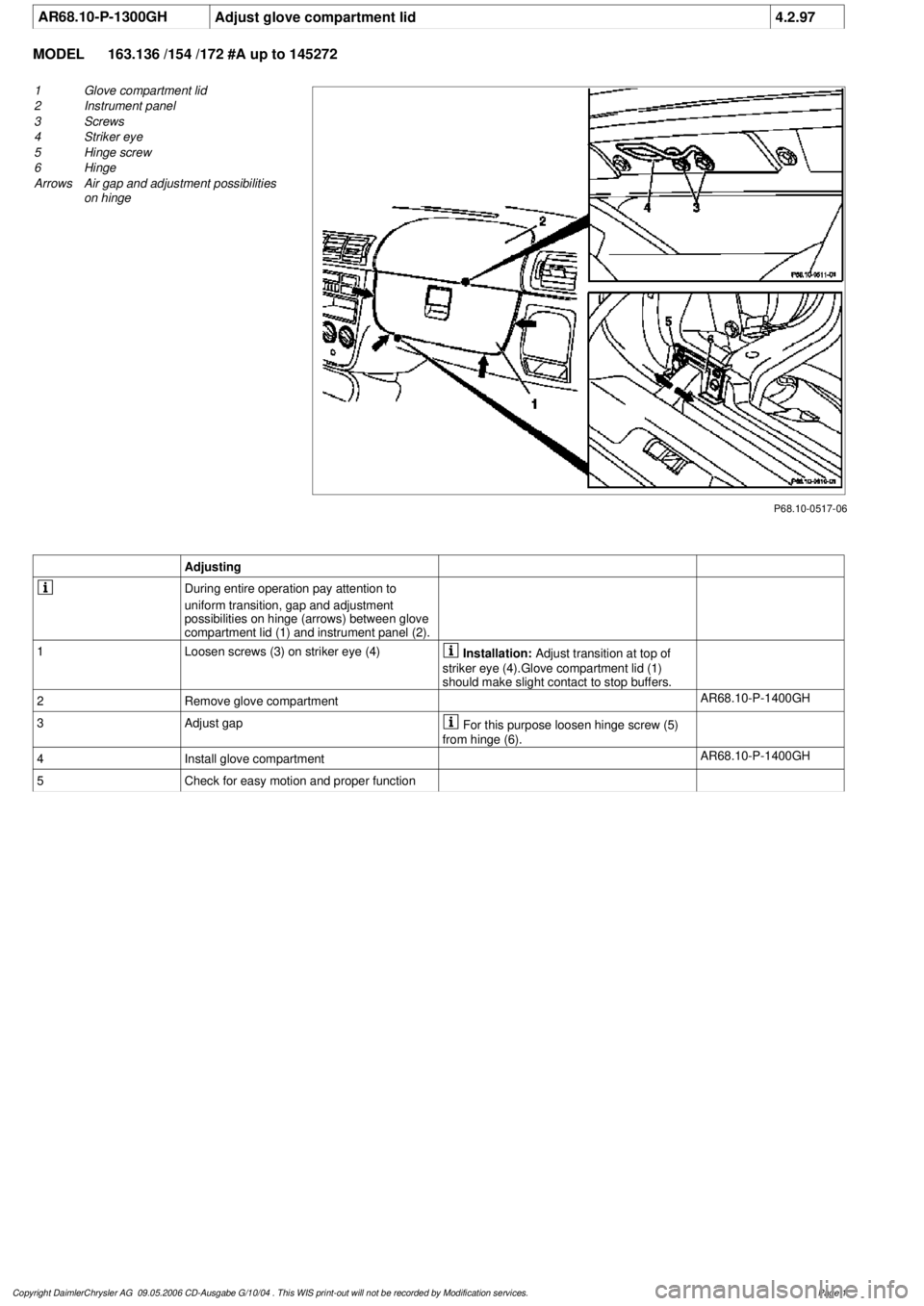
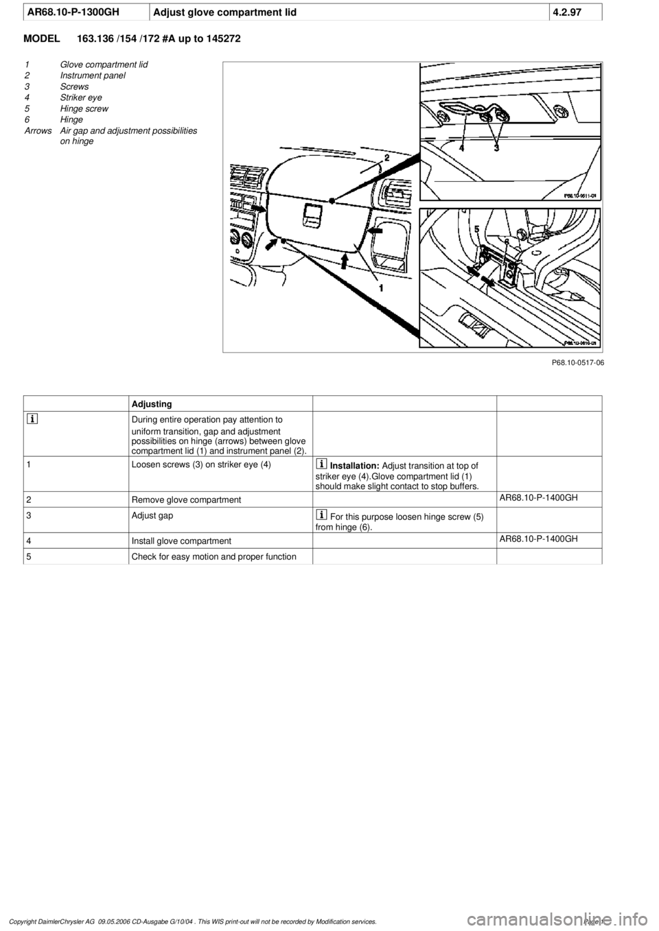
P68.10-0517-06
1
Glove compartment lid
2
Instrument panel
3
Screws
4
Striker eye
5
Hinge screw
6
Hinge
Arrows
Air gap and adjustment possibilities
on hinge
Adjusting
During entire operation pay attention to
uniform transition, gap and adjustment
possibilities on hinge (arrows) between glove
compartment lid (1) and instrument panel (2).
1
Loosen screws (3) on striker eye (4)
Installation:
Adjust transition at top of
striker eye (4).Glove compartment lid (1)
should make slight contact to stop buffers.
2
Remove glove compartment
AR68.10-P-1400GH
3
Adjust gap
For this purpose loosen hinge screw (5)
from hinge (6).
4
Install glove compartment
AR68.10-P-1400GH
5
Check for easy motion and proper function
Copyright DaimlerChrysler AG 09.05.2006 CD-Ausgabe G/10/04 . This WIS print-out will not be recorde
d by Modification services.
Page 1
Page 3180 of 4133
AR68.10-P-1300GH
Adjust glove compartment lid
4.2.97
MODEL
163.136 /154 /172 #A up to 145272
P68.10-0517-06
1
Glove compartment lid
2
Instrument panel
3
Screws
4
Striker eye
5
Hinge screw
6
Hinge
Arrows
Air gap and adjustment possibilities
on hinge
Adjusting
During entire operation pay attention to
uniform transition, gap and adjustment
possibilities on hinge (arrows) between glove
compartment lid (1) and instrument panel (2).
1
Loosen screws (3) on striker eye (4)
Installation:
Adjust transition at top of
striker eye (4).Glove compartment lid (1)
should make slight contact to stop buffers.
2
Remove glove compartment
AR68.10-P-1400GH
3
Adjust gap
For this purpose loosen hinge screw (5)
from hinge (6).
4
Install glove compartment
AR68.10-P-1400GH
5
Check for easy motion and proper function
Copyright DaimlerChrysler AG 09.05.2006 CD-Ausgabe G/10/04 . This WIS print-out will not be recorde
d by Modification services.
Page 1
Page 3197 of 4133
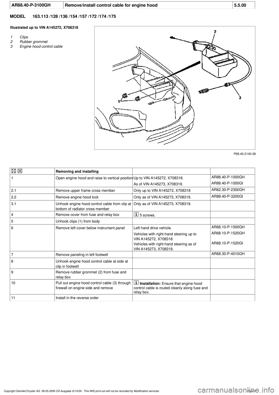
AR88.40-P-3100GH
Remove/install control cable for engine hood
5.5.00
MODEL
163.113 /128 /136 /154 /157 /172 /174 /175
P88.40-2140-06
Illustrated up to VIN A145272, X708318
1
Clips
2
Rubber grommet
3
Engine hood control cable
Removing and installing
1
Open engine hood and raise to vertical position
Up to VIN A145272, X708318.
AR88.40-P-1000GH
As of VIN A145273, X708319.
AR88.40-P-1000GI
2.1
Remove upper frame cross member
Only up to VIN A145272, X708318
AR62.30-P-2300GH
2.2Remove engine hood lock
Only as of VIN A145273, X708319.
AR88.40-P-3200GI
3.1
Unhook engine hood control cable from clip at
bottom of radiator cross member
Only as of VIN A145273, X708319.
4
Remove cover from fuse and relay box
5 screws.
5
Unhook clips (1) from body
6
Remove left cover below instrument panel
Left hand drive vehicle.
AR68.10-P-1500GH
Vehicles with right-hand steering up to
VIN A145272, X708318.
AR68.10-P-1520GH
Vehicles with right-hand steering as of
VIN A145273, X708319.
AR68.10-P-1520GI
7
Remove paneling in left footwell
AR68.30-P-4010GH
8
Unhook engine hood control cable at side at
clip in footwell
9
Remove rubber grommet (2) from fuse and
relay box
10
Pull out engine hood control cable (3) through
firewall on engine side and remove
Installation:
Ensure that engine hood
control cable is routed cleanly along fuse and
relay box.
11
Install in the reverse order
Copyright DaimlerChrysler AG 09.05.2006 CD-Ausgabe G/10/04 . This WIS print-out will not be recorde
d by Modification services.
Page 1
Page 3201 of 4133
Danger!
Risk of explosion
from explosive gas.
Risk
of poisoning and caustic burns from
swallowing battery electrolyte.
Risk of injury
through burns to skin and eyes from battery
acid or when handling damaged lead-acid
batteries
No fire, sparks, naked flames or smoking.
Wear protective gloves, acid-resistant
clothing and safety glasses. Pour battery
electrolyte only into suitable and appropriately
marked containers.
AS54.10-Z-0001-01A
4
Remove battery
AR54.10-P-0005GH
5
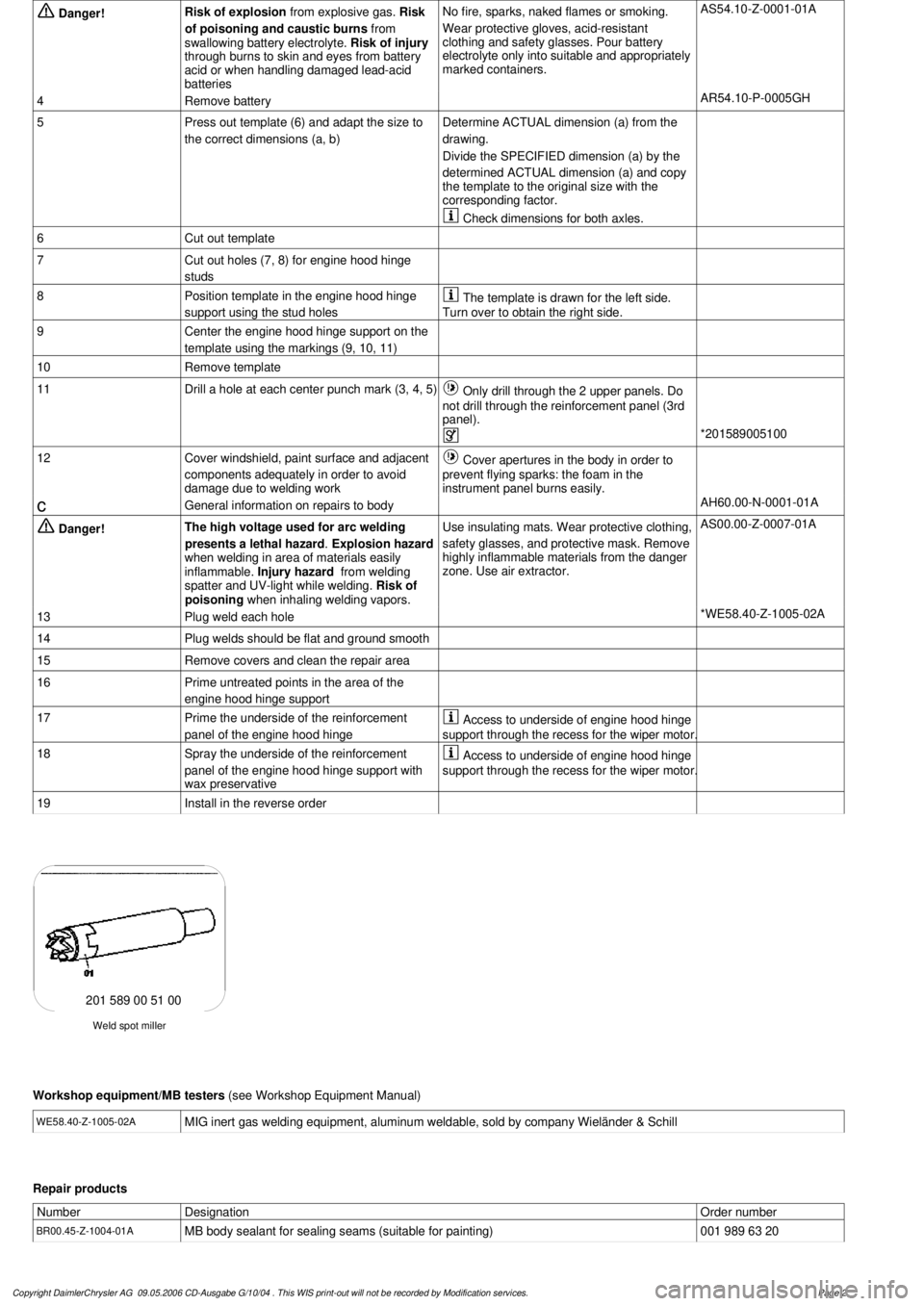
Press out template (6) and adapt the size to
the correct dimensions (a, b)Determine ACTUAL dimension (a) from the
drawing.
Divide the SPECIFIED dimension (a) by the
determined ACTUAL dimension (a) and copy
the template to the original size with the
corresponding factor.
Check dimensions for both axles.
6
Cut out template
7
Cut out holes (7, 8) for engine hood hinge
studs
8
Position template in the engine hood hinge
support using the stud holes
The template is drawn for the left side.
Turn over to obtain the right side.
9
Center the engine hood hinge support on the
template using the markings (9, 10, 11)
10
Remove template
11
Drill a hole at each center punch mark (3, 4, 5)
Only drill through the 2 upper panels. Do
not drill through the reinforcement panel (3rd
panel).
*201589005100
12
Cover windshield, paint surface and adjacent
components adequately in order to avoid
damage due to welding work
Cover apertures in the body in order to
prevent flying sparks: the foam in the
instrument panel burns easily.
c
General information on repairs to body
AH60.00-N-0001-01A
Danger!
The high voltage used for arc welding
presents a lethal hazard
.
Explosion hazard
when welding in area of materials easily
inflammable.
Injury hazard
from welding
spatter and UV-light while welding.
Risk of
poisoning
when inhaling welding vapors.
Use insulating mats. Wear protective clothing,
safety glasses, and protective mask.
Remove
highly inflammable materials from the danger
zone. Use air extractor.
AS00.00-Z-0007-01A
13
Plug weld each hole
*WE58.40-Z-1005-02A
14
Plug welds should be flat and ground smooth
15
Remove covers and clean the repair area
16
Prime untreated points in the area of the
engine hood hinge support
17
Prime the underside of the reinforcement
panel of the engine hood hinge
Access to underside of engine hood hinge
support through the recess for the wiper motor.
18
Spray the underside of the reinforcement
panel of the engine hood hinge support with
wax preservative
Access to underside of engine hood hinge
support through the recess for the wiper motor.
19
Install in the reverse order
Weld spot miller
201 589 00 51 00
Workshop equipment/MB testers
(see Workshop Equipment Manual)
WE58.40-Z-1005-02A
MIG inert gas welding equipment, aluminum weldable, sold by company Wieländer & Schill
Repair products
Number
Designation
Order number
BR00.45-Z-1004-01A
MB body sealant for sealing seams (suitable for painting)
001 989 63 20
Copyright DaimlerChrysler AG 09.05.2006 CD-Ausgabe G/10/04 . This WIS print-out will not be recorde
d by Modification services.
Page 2
Page 3204 of 4133
3
Remove engine hood hinge on the front
passenger side
AR88.40-P-3060GH
*BR00.45-Z-1004-01A
Danger!
Risk of explosion
from explosive gas.
Risk
of poisoning and caustic burns from
swallowing battery electrolyte.
Risk of injury
through burns to skin and eyes from battery
acid or when handling damaged lead-acid
batteries
No fire, sparks, naked flames or smoking.
Wear protective gloves, acid-resistant
clothing and safety glasses. Pour battery
electrolyte only into suitable and appropriately
marked containers.
AS54.10-Z-0001-01A
4
Remove battery
AR54.10-P-0005GH
5
Remove air conditioning blower motor
AR83.30-P-5560GH
6
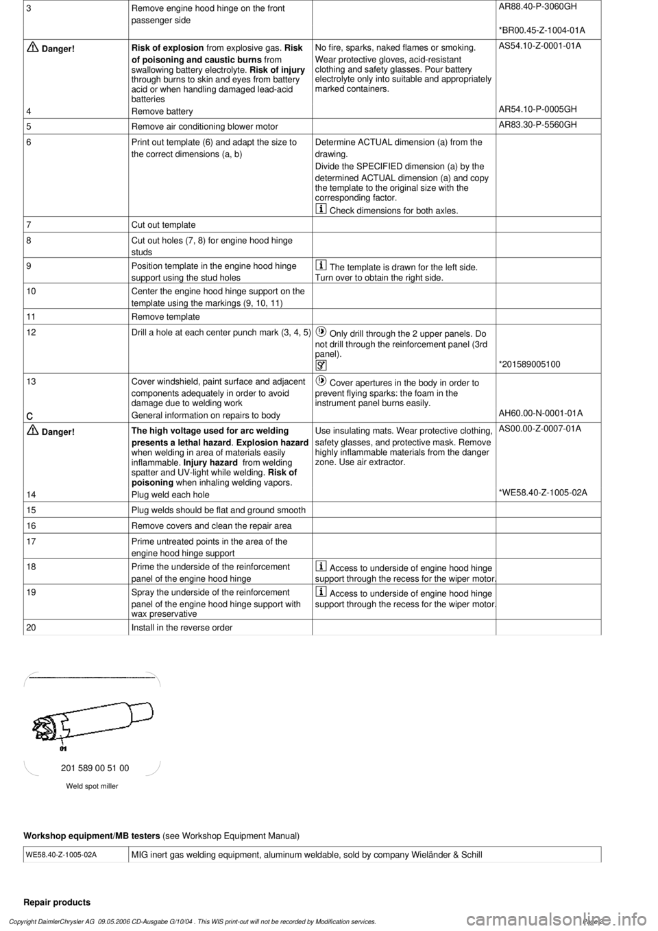
Print out template (6) and adapt the size to
the correct dimensions (a, b)Determine ACTUAL dimension (a) from the
drawing.
Divide the SPECIFIED dimension (a) by the
determined ACTUAL dimension (a) and copy
the template to the original size with the
corresponding factor.
Check dimensions for both axles.
7
Cut out template
8
Cut out holes (7, 8) for engine hood hinge
studs
9
Position template in the engine hood hinge
support using the stud holes
The template is drawn for the left side.
Turn over to obtain the right side.
10
Center the engine hood hinge support on the
template using the markings (9, 10, 11)
11
Remove template
12
Drill a hole at each center punch mark (3, 4, 5)
Only drill through the 2 upper panels. Do
not drill through the reinforcement panel (3rd
panel).
*201589005100
13
Cover windshield, paint surface and adjacent
components adequately in order to avoid
damage due to welding work
Cover apertures in the body in order to
prevent flying sparks: the foam in the
instrument panel burns easily.
c
General information on repairs to body
AH60.00-N-0001-01A
Danger!
The high voltage used for arc welding
presents a lethal hazard
.
Explosion hazard
when welding in area of materials easily
inflammable.
Injury hazard
from welding
spatter and UV-light while welding.
Risk of
poisoning
when inhaling welding vapors.
Use insulating mats. Wear protective clothing,
safety glasses, and protective mask.
Remove
highly inflammable materials from the danger
zone. Use air extractor.
AS00.00-Z-0007-01A
14
Plug weld each hole
*WE58.40-Z-1005-02A
15
Plug welds should be flat and ground smooth
16
Remove covers and clean the repair area
17
Prime untreated points in the area of the
engine hood hinge support
18
Prime the underside of the reinforcement
panel of the engine hood hinge
Access to underside of engine hood hinge
support through the recess for the wiper motor.
19
Spray the underside of the reinforcement
panel of the engine hood hinge support with
wax preservative
Access to underside of engine hood hinge
support through the recess for the wiper motor.
20
Install in the reverse order
Weld spot miller
201 589 00 51 00
Workshop equipment/MB testers
(see Workshop Equipment Manual)
WE58.40-Z-1005-02A
MIG inert gas welding equipment, aluminum weldable, sold by company Wieländer & Schill
Repair products
Copyright DaimlerChrysler AG 09.05.2006 CD-Ausgabe G/10/04 . This WIS print-out will not be recorde
d by Modification services.
Page 2
Page 3214 of 4133
Mode control knob controls air distribution throughout the passenger compartment. Air distribution doors are
controlled by cables activated by the mode control knob. See Fig. 1
. Four mode positions are available with
detents in-between to adjust airflow for personal comfort.
Defrost
Set mode control knob to 12-o'clock position. Air will exit from defrost outlets and side window vents.
Vent
Set mode control knob to 9-o'clock position. Air will exit from instrument panel outlets.
Floor
Set mode control knob to 6-o'clock position. Air will exit from floor outlets.
Blend/Bi-Level
Set mode control knob to 3-o'clock position. Air will exit from defrost, instrument panel, and floor outlets.
TEMPERATURE CONTROL KNOB
Air temperature is controlled by a variable resistor rotary control switch. See Fig. 1 . Switch receives voltage
signal and depending upon position, controls voltage signal sent to air mix damper door motor. See Fig. 2
.
Volta
ge controls position of motor for heating and cooling.
2001 Mercedes-Benz ML320
2000-01 MANUAL A/C-HEATER SYSTEMS ML 320, ML 430 & ML 55
me
Saturday, October 02, 2010 3:25:10 PMPage 3 © 2006 Mitchell Repair Information Company, LLC.