Page 1810 of 4133
REMOVE/INSTALL ANTENNA SPLITTER - AR82.70-P-8953GH
MODEL 163.113 /136 /154 /157 /172 /174
the radio
3Remove cover under
instrument panel on driver's
side AR68.10-P-1500GH
4Unscrew screw on Sound
amplifier (A2/13) and
disconnect D2 B-plug
5Cut the existing D2B wiring
harness as far as possible away
from the plug for the sound
amplifier
Install
6Plug the plug of the exchange
D2B wiring harness into the
sound amplifier (A2/13)
7Fasten sound amplifier (A2/13)
with screw
8Route exchange D2B wiring
harness (1) along existing
wiring harness to the center of
the instrument panel Danger of breaking! Do
not kink or stretch fiber optic
cable Before routing, push
the caps onto the plugs.AR82.95-P-0005-
01A
9Route exchange D2B wiring
harness (1) next to the heater
housing (2) downwards and
behind the bracket of the
control module for automatic
transmission/connector for
interior wiring harness Ensure that the D2B
wiring harness does not cross
other lines/wiring harnesses.
Fasten existing D2B wiring
harness to existing wiring
harness using tie straps.
10Route exchange D2B wiring
harness (1) upwards to the
radio installation opening Fasten D2B wiring
harness to existing wiring
harness using tie straps.
11Install cover under the
instrument panel on the driver's
side AR68.10-P-1500GH
12Plug the plug of the exchange
D2B wiring harness (1) into the
radio
13Install radio AR82.60-P-7502EA
2001 Mercedes-Benz ML320
1998-2005 ACCESSORIES & BODY, CAB Electrical System - Body - 163 Chassis
me
Saturday, October 02, 2010 3:30:10 PMPage 315 © 2006 Mitchell Repair Information Company, LLC.
Page 1816 of 4133
![MERCEDES-BENZ ML430 1997 Complete Repair Manual E-call control module/
CTEL [TEL] interface
and replace with the
white insert of the
exchange D2B wiring
harnessvoice control system (SBS) is
installed, the white D2B insert
should be removed f MERCEDES-BENZ ML430 1997 Complete Repair Manual E-call control module/
CTEL [TEL] interface
and replace with the
white insert of the
exchange D2B wiring
harnessvoice control system (SBS) is
installed, the white D2B insert
should be removed f](/manual-img/4/57307/w960_57307-1815.png)
E-call control module/
CTEL [TEL] interface
and replace with the
white insert of the
exchange D2B wiring
harnessvoice control system (SBS) is
installed, the white D2B insert
should be removed from the
voice control system control
module and not from the E-call
control module/CTEL [TEL]
interface.
Pay attention to the correct
installation position of the insert
in the D2B plug. Cut off the
fiber optical cable removed at
the adhesive tape.
5Route exchange D2B
wiring harness (1)
under the floor
covering to the
transmission tunnel
6Route exchange D2B
wiring harness (1) at
the top of the
transmission tunnel to
the center part of the
instrument panel Route fiber optical cable
under the air duct. Guide it past
all components on the left side.
7Route exchange D2B
wiring harness (1)
behind the instrument
panel to the radio
installation opening
8Remove red insert of
the D2B wiring harness
from the D2B plug on
the radio and replace
with the red insert of
the exchange D2B
wiring harness Risk of breakage! Do not
kink or stretch fiber optic cable
Pay attention to the correct
installation position of the insert
in the D2 B-plug. Cut off the
fiber optical cable removed at
the adhesive tape.AR82.70-P-0004-01A
9Fasten exchange D2B
wiring harness (1) to
the existing D2B
wiring harness of the
radio
10.1Install CTEL [TEL]
interface (A34/4) with
bracket Only with complete portable
CTEL-preinstallation on dome,
code 852 or with MB portable
CTEL, code 854.
*BA91.10-P-1001-01B
*BA91.40-P-1001-01D
2001 Mercedes-Benz ML320
1998-2005 ACCESSORIES & BODY, CAB Electrical System - Body - 163 Chassis
me
Saturday, October 02, 2010 3:30:10 PMPage 321 © 2006 Mitchell Repair Information Company, LLC.
Page 1827 of 4133
Fig. 236: Identifying Retrofit Navigation System Audio 30 APS Components
Notes on assignment for
radio connectorModel 163AH82.61-P-0001-05A
Notes on telephone
operation with Audio 30
APS navigation systemModel 129, 163, 168,
170, 202, 208, 210AH82.61-P-0001-06A
Removal
1Disconnect ground cable
of battery
AR54.10-P-0003A
2Remove radio The Audio 30 APS
radio is installed.
AR82.60-P-7502EA
3Remove center console
AR68.20-P-2000GH
4Remove cover below
instrument panel on left On vehicles up to
06/99
AR68.10-P-1500GH
5Remove diagnostic
socket On vehicles up to
06/99
Install
6Retrofit global position AN82.61-P-7474-04AZ
2001 Mercedes-Benz ML320
1998-2005 ACCESSORIES & BODY, CAB Electrical System - Body - 163 Chassis
me
Saturday, October 02, 2010 3:30:10 PMPage 332 © 2006 Mitchell Repair Information Company, LLC.
Page 1840 of 4133
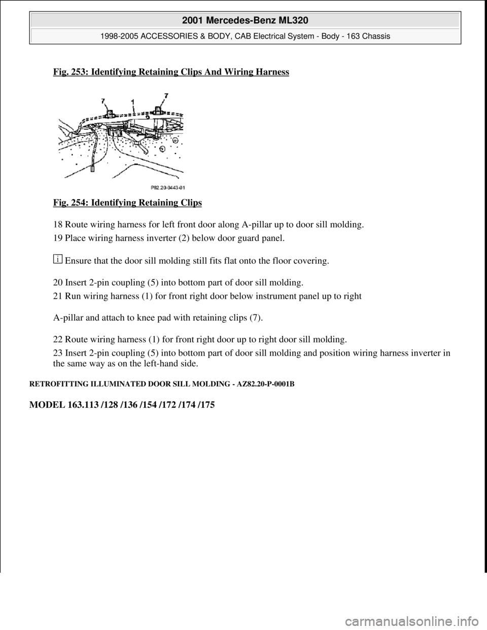
Fig. 253: Identifying Retaining Clips And Wiring Harness
Fig. 254: Identifying Retaining Clips
18 Route wiring harness for left front door along A-pillar up to door sill molding.
19 Place wiring harness inverter (2) below door guard panel.
Ensure that the door sill molding still fits flat onto the floor covering.
20 Insert 2-pin coupling (5) into bottom part of door sill molding.
21 Run wiring harness (1) for front right door below instrument panel up to right
A-pillar and attach to knee pad with retaining clips (7).
22 Route wiring harness (1) for front right door up to right door sill molding.
23 Insert 2-pin coupling (5) into bottom part of door sill molding and position wiring harness inverter in
the same way as on the left-hand side.
RETROFITTING ILLUMINATED DOOR SILL MOLDING - AZ82.20-P-0001B
MODEL 163.113 /128 /136 /154 /172 /174 /175
2001 Mercedes-Benz ML320
1998-2005 ACCESSORIES & BODY, CAB Electrical System - Body - 163 Chassis
me
Saturday, October 02, 2010 3:30:11 PMPage 345 © 2006 Mitchell Repair Information Company, LLC.
Page 1842 of 4133
driver sidemiddle in order to avoid
damaging the retaining
clips.
As of VINA145273,
X708319: Begin at the
front in order to avoid
damaging the retaining
clips.
Fig. 155
6Take out the two
frontmost screws of the
door sill molding at the
right and left driver side
7Pull off door rubber seal
at bottom of right and left
driver door
8Remove cover below left
of instrument panel
AR68.10-P-1500GH
9Remove cover below
instrument panel on right
Up to VIN A145272,
X708318AR68.10-P-1520GH
As of VIN A145273,
X708319AR68.10-P-1520GI
10Remove right and left
paneling in footwell
AR68.30-P-4010GH
Install
11Install wiring harness for
illuminated door sill
molding and connect AZ82.20-P-0001-02B
12Insert the front screws of
the right and left door sill
molding trim
13Stick luminous foil onto
rear of illuminated door
sill molding The silver side of the
luminous foil is the
underside. Pull off
protective foil of the
double-sided adhesive
tape on the rear of the
door sill molding and
stick on luminous foil.
14Connect illuminated door
2001 Mercedes-Benz ML320
1998-2005 ACCESSORIES & BODY, CAB Electrical System - Body - 163 Chassis
me
Saturday, October 02, 2010 3:30:11 PMPage 347 © 2006 Mitchell Repair Information Company, LLC.
Page 1845 of 4133
If fitted.
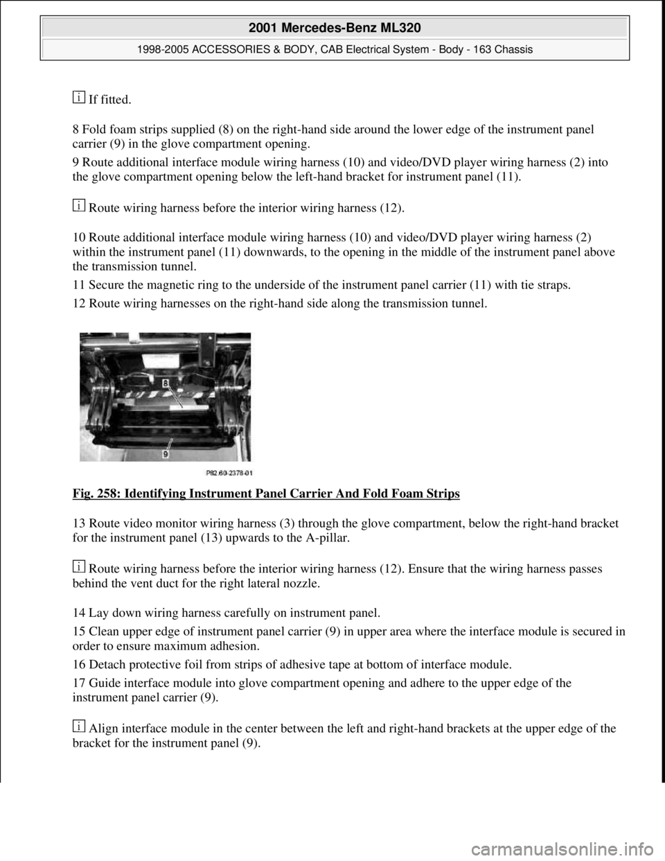
8 Fold foam strips supplied (8) on the right-hand side around the lower edge of the instrument panel
carrier (9) in the glove compartment opening.
9 Route additional interface module wiring harness (10) and video/DVD player wiring harness (2) into
the glove compartment opening below the left-hand bracket for instrument panel (11).
Route wiring harness before the interior wiring harness (12).
10 Route additional interface module wiring harness (10) and video/DVD player wiring harness (2)
within the instrument panel (11) downwards, to the opening in the middle of the instrument panel above
the transmission tunnel.
11 Secure the magnetic ring to the underside of the instrument panel carrier (11) with tie straps.
12 Route wiring harnesses on the right-hand side along the transmission tunnel.
Fig. 258: Identifying Instrument Panel Carrier And Fold Foam Strips
13 Route video monitor wiring harness (3) through the glove compartment, below the right-hand bracket
for the instrument panel (13) upwards to the A-pillar.
Route wiring harness before the interior wiring harness (12). Ensure that the wiring harness passes
behind the vent duct for the right lateral nozzle.
14 Lay down wiring harness carefully on instrument panel.
15 Clean upper edge of instrument panel carrier (9) in upper area where the interface module is secured in
order to ensure maximum adhesion.
16 Detach protective foil from strips of adhesive tape at bottom of interface module.
17 Guide interface module into glove compartment opening and adhere to the upper edge of the
instrument panel carrier (9).
Align interface module in the center between the left and right-hand brackets at the upper edge of the
bracket for the instrument panel (9).
2001 Mercedes-Benz ML320
1998-2005 ACCESSORIES & BODY, CAB Electrical System - Body - 163 Chassis
me
Saturday, October 02, 2010 3:30:11 PMPage 350 © 2006 Mitchell Repair Information Company, LLC.
Page 1846 of 4133
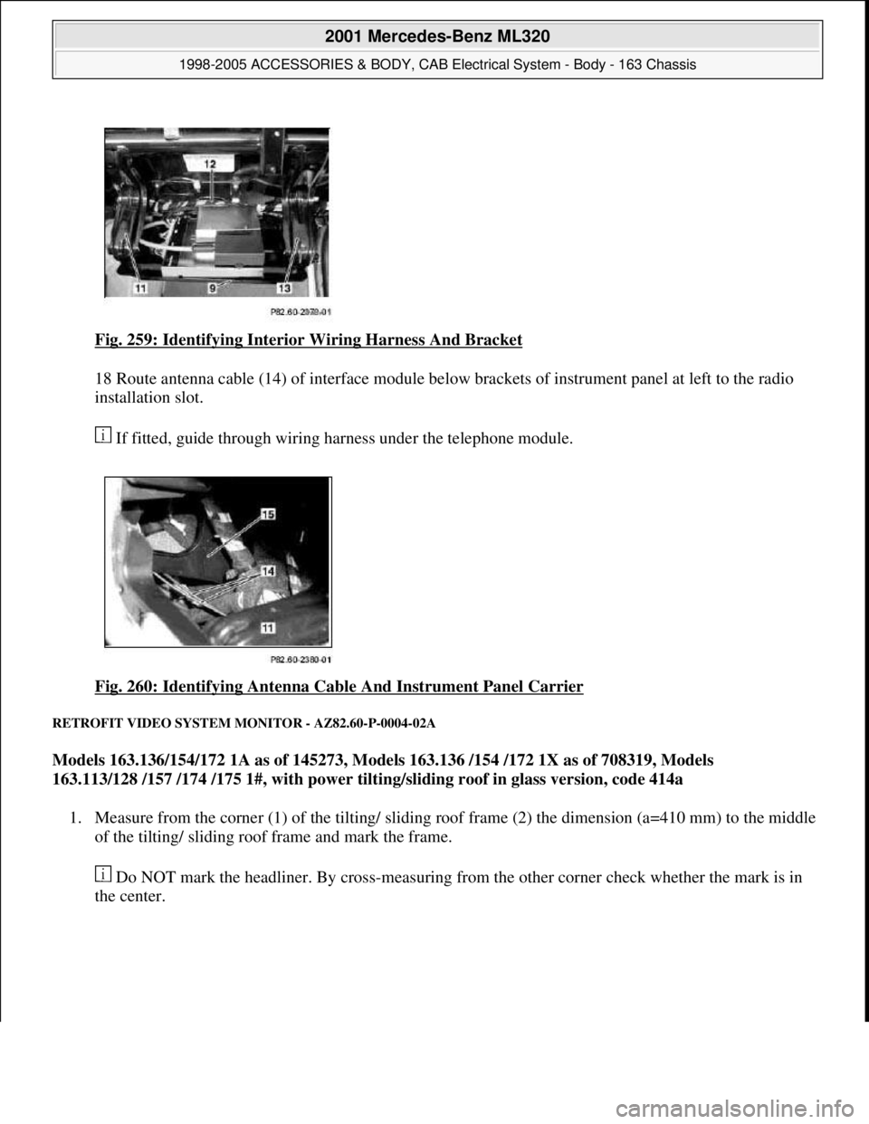
Fig. 259: Identifying Interior Wiring Harness And Bracket
18 Route antenna cable (14) of interface module below brackets of instrument panel at left to the radio
installation slot.
If fitted, guide through wiring harness under the telephone module.
Fig. 260: Identifying Antenna Cable And Instrument Panel Carrier
RETROFIT VIDEO SYSTEM MONITOR - AZ82.60-P-0004-02A
Models 163.136/154/172 1A as of 145273, Models 163.136 /154 /172 1X as of 708319, Models
163.113/128 /157 /174 /175 1#, with power tilting/sliding roof in glass version, code 414a
1. Measure from the corner (1) of the tilting/ sliding roof frame (2) the dimension (a=410 mm) to the middle
of the tilting/ sliding roof frame and mark the frame.
Do NOT mark the headliner. By cross-measuring from the other corner check whether the mark is in
the center.
2001 Mercedes-Benz ML320
1998-2005 ACCESSORIES & BODY, CAB Electrical System - Body - 163 Chassis
me
Saturday, October 02, 2010 3:30:11 PMPage 351 © 2006 Mitchell Repair Information Company, LLC.
Page 1881 of 4133
Fig. 301: Identifying Video/DVD Player, Striker And Locking Arm
RETROFIT VOLTAGE SUPPLY FOR CENTRAL INTERFACE MODULE - AZ82.60-P-0004-06A
Model 163.136 /154 /172 #A as of 145273, Models 163.136 /154 /172 #X as of 708319, Models
163.113/128 /157 /174 /175
1. Remove cover for fuse unit in right footwell.
Turn arresting mechanisms counterclockwise and move out cover to the rear.
2. Route plug for voltage supply (1) for the interface module of the fuse unit into the glove compartment
opening.
Guide cable under the right-hand instrument panel support (2).
View of left-hand steering installation
2001 Mercedes-Benz ML320
1998-2005 ACCESSORIES & BODY, CAB Electrical System - Body - 163 Chassis
me
Saturday, October 02, 2010 3:30:12 PMPage 386 © 2006 Mitchell Repair Information Company, LLC.