Page 204 of 4133

154 Tele Aid
Te ch n ica l
data Instruments
and controlsOperationDrivingInstrument
cluster displayPractical hints Car care Index
If the indicator lamp in the Roadside Assistance
button• is illuminated continuously and there was
no voice connection to the Response Center established,
then the Tele Aid system could not initiate an Roadside
Assistance call (e.g. the relevant cellular phone network
is not available). The message “ROADSIDE
ASSISTANCE – CALL FAILED” appears in the MCS
display.
Should this occur, assistance must be summoned by
other means.
Roadside Assistance calls can be terminated using the
END button on the MCS unit.Information button ¡
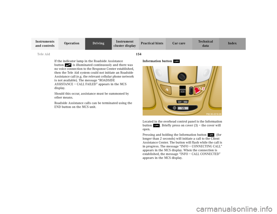
Located in the overhead control panel is the Information
button¡. Briefly press on cover (3) – the cover will
open.
Pressing and holding the Information button¡ (for
longer than 2 seconds) will initiate a call to the Client
Assistance Center. The button will flash while the call is
in progress. The message “INFO – CONNECTING CALL”
appears in the MCS display. When the connection is
established, the message “INFO – CALL CONNECTED”
appears in the MCS display.
�����������������������������������������������������������������������������������������������������
RESET
MODE
3
Page 223 of 4133
173 Parking brake
Te ch n ica l
data Instruments
and controlsOperationDrivingInstrument
cluster displayPractical hints Car care Index Parking brake
To engage, firmly depress parking brake pedal (1).
When the key is in steering lock position 2, the brake
warning lampÉ in the instrument cluster should
come on brightly.To release the parking brake, pull handle (2) on
instrument panel. The brake warning lampÉ in the
instrument cluster should go out.
A warning sounds, if you start to drive without having
released the parking brake.
Also see brake warning lamp on page 219.
Wa r n i n g !
When leaving the vehicle always remove the key
from the steering lock, and lock the vehicle. Do not
leave children unattended in the vehicle, or with
access to an unlocked vehicle. Children could
release the parking brake, which could result in an
accident or serious injury.
Page 259 of 4133

209 Driving systems
Te ch n ica l
data Instruments
and controlsOperationDrivingInstrument
cluster displayPractical hints Car care Index Transmission control – LOW RANGE mode
The switch is located in the instrument panel.
Important!
When switching to or from the LOW RANGE mode,
observe the following:
•The vehicle must be at a complete standstill.
•The engine speed must not exceed 1500 rpm.Failure to do so may result in transmission / engine
damage not covered by the Mercedes-Benz Limited
Warranty
The LOW RANGE mode should be switched on:
•during off-road driving,
•when crossing waters.
For additional practical hints refer to off-road driving
on page 183.
Switching on:
1. Sto p t h e v e h i c l e .
2. Move transmission selector lever to position “N”.
3. Push top end of switch. The LOW RANGE indicator
lamp in the instrument cluster blinks slowly during
the changeover.
Once the changeover is complete, the indicator lamp in
the instrument cluster lights up continuously.
Note:
If the indicator lamp blinks fast, one or more switching
conditions were not observed, or the LOW RANGE mode
is defective.
Page 278 of 4133
228 First aid kit
Te ch n ica l
data Instruments
and controlsOperation DrivingInstrument
cluster displayPractical hintsCar care Index
First aid kit
All except model ML 55 AMG:
The first aid kit is located behind the cover in the left
rear cargo compartment trim panel.
Turn both handles (1) left and open cover.
Model ML 55 AMG:
The first aid kit is stored inside the spare wheel cover
located in the cargo compartment.
Open buckles and remove spare wheel cover,
see page 242.Fuses
Before replacing a blown fuse, determine the cause of
the short circuit.
Spare fuses and a special fuse puller are supplied inside
the fuse box cover. Observe amperage and color of fuse.
Always use a new fuse for replacement. Never attempt to
repair or bridge a blown fuse.
A fuse chart can be found inside the corresponding fuse
box cover.
Page 281 of 4133
231 Engine compartment
Te ch n ica l
data Instruments
and controlsOperation DrivingInstrument
cluster displayPractical hintsCar care Index Hood
To o pen :
To unlock the hood, pull release lever (1) under the
driver’s side of the instrument panel. At the same time a
handle (2) will extend out of the radiator grill (it may be
necessary to lift the hood up slightly).
Caution!
To avoid damage to the windshield wipers or hood, open
the hood only with wipers in the parked position.Pull handle (2) to its stop out of radiator grill and open
hood (do not pull up on handle).
To c l o s e :
Lower hood and let it drop into lock from a height of
approximately 1 ft. (30 cm).
To avoid hood damage, please make sure that hood is
fully closed. If not, repeat closing procedure. Do not
push down on hood to attempt to fully close it.
Page 288 of 4133
238 Spare wheel, vehicle jack
Te ch n ica l
data Instruments
and controlsOperation DrivingInstrument
cluster displayPractical hintsCar care Index
The vehicle jack, wheel bolt wrench and screwdriver are
located in the rear cargo compartment behind the cover
in the right side trim panel.
To get to tools, first remove trim panel cover by turning
both handles to left, and then swing aside CD-player (if
so equipped).Unscrew plastic nut (1) and lift out vehicle jack.
See illustration for proper storage of jack and wheel bolt
wrench.
Warnung!Sich nicht unter
das nur mit dem W
agenheber
aufgebockte Fahrzeug begeben!Warnung!Sich nicht unter
das nur mit dem W
agenheber
aufgebockte Fahrzeug begeben!
Page 298 of 4133

248 Tires, Wheels
Te ch n ica l
data Instruments
and controlsOperation DrivingInstrument
cluster displayPractical hintsCar care Index
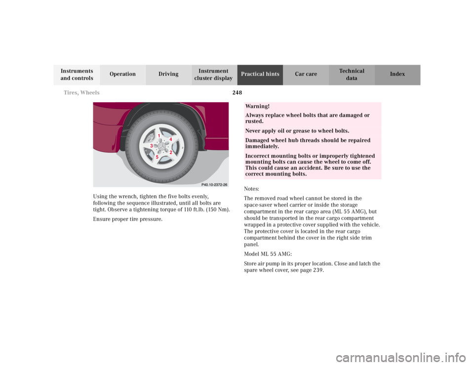
Using the wrench, tighten the five bolts evenly,
following the sequence illustrated, until all bolts are
tight. Observe a tightening torque of 110 ft.lb. (150 Nm).
Ensure proper tire pressure.Notes:
The removed road wheel cannot be stored in the
space-saver wheel carrier or inside the storage
compartment in the rear cargo area (ML 55 AMG), but
should be transported in the rear cargo compartment
wrapped in a protective cover supplied with the vehicle.
The protective cover is located in the rear cargo
compartment behind the cover in the right side trim
panel.
Model ML 55 AMG:
Store air pump in its proper location. Close and latch the
spare wheel cover, see page 239.
1
2
3
4
5
Wa r n i n g !
Always replace wheel bolts that are damaged or
rusted.Never apply oil or grease to wheel bolts.Damaged wheel hub threads should be repaired
immediately.Incorrect mounting bolts or improperly tightened
mounting bolts can cause the wheel to come off.
This could cause an accident. Be sure to use the
correct mounting bolts.
Page 306 of 4133
256 Towing
Te ch n ica l
data Instruments
and controlsOperation DrivingInstrument
cluster displayPractical hintsCar care Index
ML 320, ML 430The rear towing eye is located behind the right side
cover in the bumper panel.
2To w i n g eye , r e a r
Cover removal:
Using a flat blade screwdriver pry out the cover.
Cover installation:
Engage cover at bottom and press in top securely.