Page 1083 of 4133

279 Practical hints
Battery
Disconnecting the battery�
Depress parking brake firmly or move
gear selector lever to positionP.
�
Turn off all electrical consumers.
�
Remove key from the steering lock.
�
Open the hood (
�page 217).
�
Disconnect the battery negative lead.
�
Remove the cover from the positive ter-
minal.
�
Disconnect the battery positive lead.
Removing the batteries�
Remove the screw securing the bat-
tery.
�
Remove the battery support and brack-
et. Take out the battery.
Charging and reinstalling batteries�
Charge battery in accordance with the
instructions of the battery charger
manufacturer.
�
Reinstall the charged battery. Follow
the previously described steps in re-
verse order.
Reconnecting the batteries�
Turn off all electrical consumers.
�
Connect the positive lead and fasten its
cover.
�
Connect the negative lead.
Warning!
G
With a disconnected battery�
you will no longer be able to turn the key
in the steering lock
�
the gear selector lever will remain
locked in positionP
Warning!
G
Never charge a battery while still installed in
the vehicle. Gases may escape during charg-
ing and cause explosions that may result in
paint damage, corrosion or personal injury.
!Never invert the terminal connections!!The battery, its filler caps and the vent
tube must always be securely installed
when the vehicle is in operation.
Page 1084 of 4133
280 Practical hintsBattery
Batteries contain materials that can harm
the environment if disposed of improperly.
Large 12-volt storage batteries contain
lead. Recycling of batteries is the preferred
method of disposal. Many states require
sellers of batteries to accept old batteries
for recycling.
iThe following procedures must be car-
ried out following any interruption of
battery power (e.g. due to reconnec-
tion):�
Set the clock (
�page 118).
�
Set the date in trip computer
(�page 186).
�
Calibrate the compass
(�page 188).
�
Resynchronize the ESP
(�page 246).
�
Resynchronize side power windows
(�page 146).
�
Resynchronize sliding / pop-up
roof*(
�page 149).
Page 1085 of 4133

281 Practical hints
Jump starting
�Jump starting
If the battery is discharged, the engine can
be started with jumper cables and the bat-
tery of another vehicle. Observe the follow-
ing:�
Jump starting should only be performed
when the engine and catalytic convert-
er are cold.
�
Do not start the engine if the battery is
frozen. Let the battery thaw out first.
�
Only jump start from batteries with the
same voltage rating (12 V). Jump start-
ing with a more powerful battery could
damage the vehicle's electrical system,
which will not be covered by the
Mercedes-Benz Limited Warranty.
�
Use only jumper cables with sufficient-
cross-section and insulated terminal
clamps.
�
Always make sure the jumper cables
are not on or near pulleys, fans or other
parts that move when the engine is
started or running.
Warning!
G
Failure to follow these directions will cause
damage to the electronic components, and
can lead to a battery explosion and severe
injury or death.
Never lean over batteries while connecting
or jump starting, you might get injured.
Battery fluid contains sulfuric acid. Do not
allow this fluid to come in contact with eyes,
skin or clothing. In case it does, immediately
flush affected area with water, and seek
medical help if necessary.
A battery will also produce hydrogen gas,
which is flammable and very explosive. Keep
flames or sparks away from battery, avoid
improper connection of jumper cables,
smoking, etc.
Attempting to jump start a frozen battery
can result in it exploding, causing personal
injury.
Read all instructions before proceeding.
!Avoid repeated and lengthy starting at-
tempts.
Do not attempt to start the engine us-
ing a battery quick charge unit.
If engine does not run after several un-
successful starting attempts, have it
checked at the nearest authorized
Mercedes-Benz Light Truck Center.
Excessive unburned fuel generated by
repeated failed starting attempts may
damage the catalytic converter and
may present a fire risk.
Make sure the jumper cables do not
have loose or missing insulation.
Make sure the cable clamps do not
touch any other metal part while the
other end is still attached to a battery.
Page 1086 of 4133

282 Practical hintsJump startingThe battery is located on the right side of
the engine compartment.�
Make sure the two vehicles do not
touch.
�
Turn off all electrical consumers.
�
Apply parking brake.
�
Shift gear selector lever to positionP.
�
Open the hood.
�
Connect positive terminals1 and4
of the batteries with the jumper cable.
Clamp cable to positive terminal4 of
charged battery first.1Positive terminal of discharged battery
2Negative terminal of discharged
battery
3Negative terminal of charged battery
4Positive terminal of charged battery
�
Start engine of the vehicle with the
charged battery and run at idle speed.
�
Connect negative terminals2 and3
of the batteries with the jumper cable.
Clamp cable to negative terminal3 of
charged battery first.
�
Start the engine of the disabled vehi-
cle.
Now you can turn on the electrical
consumers. Do not turn on the lights under
any circumstances.
�
Remove the jumper cables first from
the negative terminals2 and3 and
then from positive terminals1
and4.
You can now turn on the lights.
�
Have the battery checked at the
nearest authorized Mercedes-Benz
Light Truck Center.
Warning!
G
Keep flames or sparks away from battery.
Do not smoke.
Observe all safety instructions and precau-
tions when handling automotive batteries
(�page 223).
!Never invert the terminal connections.
!Do not tow-start the vehicle.
Page 1089 of 4133
285 Practical hints
Towing the vehicle
Front towing eye
The front towing eye is located on the pas-
senger side below the bumper.
1Towing eyeRear towing eye The rear towing eye is located behind the
right side cover in the bumper panel.
ML 350, ML 5001Cover
2Towing eye
To remove cover:�
Pry out the cover1 using a flat blade
screwdriver (
�page 257).
To reinstall cover:
�
Engage cover at bottom and press in
top securely.
iThe gear selector lever will remain
locked in positionP and the key will not
turn in the steering lock if the battery is
disconnected or discharged. See notes
on the battery (
�page 278) or on jump
starting (
�page 281).
Manual unlocking transmission gear
selector lever (
�page 264).
Warning!
G
In order to avoid possible serious burns or
injury, use extreme caution when removing
the cover, because the rear exhaust pipe is
extremely hot.
Page 1101 of 4133
297 Technical data
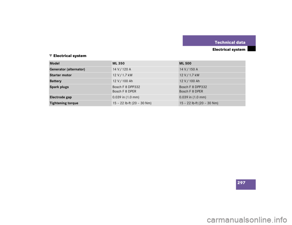
Electrical system
�Electrical system
Model
ML 350
ML 500
Generator (alternator)
14 V / 120 A
14 V / 150 A
Starter motor
12 V / 1.7 kW
12 V / 1.7 kW
Battery
12 V / 100 Ah
12 V / 100 Ah
Spark plugs
Bosch F 8 DPP332
Bosch F 8 DPER
Bosch F 8 DPP332
Bosch F 8 DPER
Electrode gap
0.039 in (1.0 mm)
0.039 in (1.0 mm)
Tightening torque
15 – 22 lb-ft (20 – 30 Nm)
15 – 22 lb-ft (20 – 30 Nm)
Page 1119 of 4133

The Tele Aid system consists of three
types of response: automatic and man-
ual emergency, roadside assistance
an")
315 Technical terms
Tele Aid System*
(T
elematic A
larm I
dentification on
D
emand)
The Tele Aid system consists of three
types of response: automatic and man-
ual emergency, roadside assistance
and information. Tele Aid is initially ac-
tivated by completing a subscriber
agreement and placing an acquain-
tance call.
The Tele Aid system is operational pro-
vided that the vehicle’s battery is
charged, properly connected, not dam-
aged and cellular and GPS coverage is
available.
Telematics*
A combination of the terms “telecom-
munications” and “informatics”.
Tightening torque
Force times lever arm (e.g. a lug
wrench) with which threaded fasteners
such as wheel bolts are tightened.Tire speed rating
Part of tire designation; indicates the
speed range for which a tire is ap-
proved.
Traction
Force exerted by the vehicle on the
road via the tires.
Transfer case
Speed of rotation / torque converter
that works together with the ->auto-
matic transmission. In the LOW mode
off-road position, the transfer case de-
creases the output rotational speed of
the ->automatic transmission by ap-
proximately half. This results in a corre-
sponding increase of torque on the
drive axles.
The vehicle then has nearly double the
driving force but drives only approxi-
mately half as fast.TWR
(T
ongue W
eight R
ating)
The TWR is the maximum permissible
weight on the trailer tongue.
VIN
(V
ehicle I
dentification N
umber)
The number set by the manufacturer
and placed on the body to uniquely
identify each vehicle produced.
Voice control system*
Voice control system for car phones,
portable cell phones and audio sys-
tems (radio, CD, etc.).
Page 1123 of 4133

319 Index
Rear passenger compartment 141
Rear window defroster 133
Residual heat utilization 140
Residual ventilation 140
Switching off 137
Switching on 137
Automatic headlamp mode 108
Automatic interior lighting control
Activating 113
Deactivating 113
Automatic locking when driving 93
Automatic transmission 119
Accelerator position 123
Emergency operation (Limp Home
Mode) 124
Gear ranges 121
Gear selector lever position 122
Gear shifting malfunctions 124
Kickdown 123
Manual shifting 120
One-touch gearshifting 120Selector lever position 119
Towing a trailer 124
Transmission fluid 222
B
BabySmart
TM
Airbag deactivation system 70
Compatible child seats 70, 311
Self-test 70
BabySmart
TM airbag deactivation
system 311
Backrest tilt 35
Backup lamps 267, 270
Bulbs 267
BAS 78, 311
Malfunction indicator lamp 245, 246,
247
Warning lamp 245, 246, 247
Batteries, remote control
Changing 262
Batteries, vehicle 223
Battery discharged
Jump starting 281Battery indicator lamp
Indicator lamp 254
Battery, vehicle 223, 278
Charging 279
Disconnecting 279
Reconnecting 279
Reinstalling 279
Removing 279
Bi-Xenon headlamps* 311
Blocking
Rear door window operation 73
Brake assist system (BAS) 311
Brake fluid 302
Brake lamp bulbs 267
Brake lamp, high mounted 267
Brake pad wear
Indicator lamp 254
Brakes 194
Warning lamp 244
Break-in period 192