Page 2209 of 4133
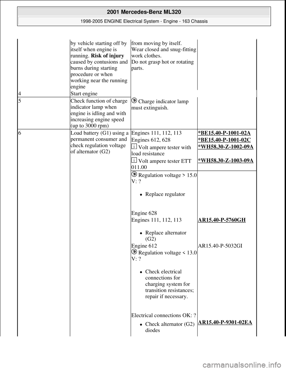
by vehicle starting off by
itself when engine is
running. Risk of injury
caused by contusions and
burns during starting
procedure or when
working near the running
enginefrom moving by itself.
Wear closed and snug-fitting
work clothes.
Do not grasp hot or rotating
parts.
4Start engine
5Check function of charge
indicator lamp when
engine is idling and with
increasing engine speed
(up to 3000 rpm) Charge indicator lamp
must extinguish.
6Load battery (G1) using a
permanent consumer and
check regulation voltage
of alternator (G2)Engines 111, 112, 113*BE15.40-P-1001-02A
Engines 612, 628*BE15.40-P-1001-02C
Volt ampere tester with
load resistance*WH58.30-Z-1002-09A
Volt ampere tester ETT
011.00*WH58.30-Z-1003-09A
Regulation voltage > 15.0
V: ?
Replace regulator
Engine 628
Engines 111, 112, 113
Replace alternator
(G2)
AR15.40-P-5760GH
Engine 612
Regulation voltage < 13.0
V: ?
Check electrical
connections for
charging system for
transition resistances;
repair if necessary.
Electrical connections OK: ?
AR15.40-P-5032GI
Check alternator (G2)
diodes AR15.40-P-9301-02EA
2001 Mercedes-Benz ML320
1998-2005 ENGINE Electrical System - Engine - 163 Chassis
me
Saturday, October 02, 2010 3:18:54 PMPage 55 © 2006 Mitchell Repair Information Company, LLC.
Page 2210 of 4133
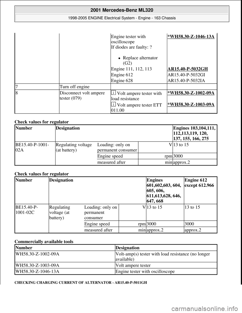
Check values for regulator
Check values for regulator
Commercially available tools
CHECKING CHARGING CURRENT OF ALTERNATOR - AR15.40-P-5011GH
Engine tester with
oscilloscope
If diodes are faulty: ?
Replace alternator
(G2)
*WH58.30-Z-1046-13A
Engine 111, 112, 113AR15.40-P-5032GH
Engine 612AR15.40-P-5032GI
Engine 628AR15.40-P-5032IA
7Turn off engine
8Disconnect volt ampere
tester (079) Volt ampere tester with
load resistance*WH58.30-Z-1002-09A
Volt ampere tester ETT
011.00*WH58.30-Z-1003-09A
NumberDesignationEngines 103,104,111,
112,113,119, 120,
137, 155, 166, 275
BE15.40-P-1001-
02ARegulating voltage
(at battery)Loading: only on
permanent consumerV13 to 15
Engine speedrpm3000
measured afterminapprox.2
NumberDesignationEngines
601,602,603, 604,
605, 606,
611,613,628, 646,
647, 668Engine 612
except 612.966
BE15.40-P-
1001-02CRegulating
voltage (at
battery)Loading: only on
permanent
consumerV13 to 1513 to 15
Engine speedrpm30003000
measured afterminapprox.2approx.2
NumberDesignation
WH58.30-Z-1002-09AVolt-amp(s) tester with load resistance (no longer
available)
WH58.30-Z-1003-09AVolt ampere tester
WH58.30-Z-1046-13AEngine tester with oscilloscope
2001 Mercedes-Benz ML320
1998-2005 ENGINE Electrical System - Engine - 163 Chassis
me
Saturday, October 02, 2010 3:18:54 PMPage 56 © 2006 Mitchell Repair Information Company, LLC.
Page 2211 of 4133
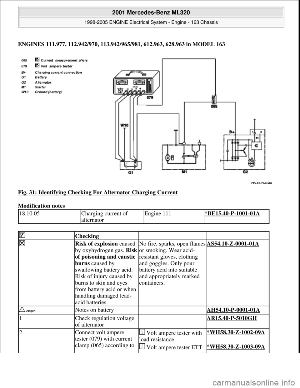
ENGINES 111.977, 112.942/970, 113.942/965/981, 612.963, 628.963 in MODEL 163
Fig. 31: Identifying Checking For Alternator Charging Current
Modification notes
18.10.05Charging current of
alternatorEngine 111*BE15.40-P-1001-01A
Checking
Risk of explosion caused
by oxyhydrogen gas. Risk
of poisoning and caustic
burns caused by
swallowing battery acid.
Risk of injury caused by
burns to skin and eyes
from battery acid or when
handling damaged lead-
acid batteriesNo fire, sparks, open flames
or smoking. Wear acid-
resistant gloves, clothing
and goggles. Only pour
battery acid into suitable
and appropriately marked
containers.AS54.10-Z-0001-01A
Notes on battery AH54.10-P-0001-01A
1Check regulation voltage
of alternator AR15.40-P-5010GH
2Connect volt ampere
tester (079) with current
clamp (065) according to Volt ampere tester with
load resistance*WH58.30-Z-1002-09A
Volt ampere tester ETT *WH58.30-Z-1003-09A
2001 Mercedes-Benz ML320
1998-2005 ENGINE Electrical System - Engine - 163 Chassis
me
Saturday, October 02, 2010 3:18:54 PMPage 57 © 2006 Mitchell Repair Information Company, LLC.
Page 2212 of 4133
connection diagram011.00
Risk of accident caused
by vehicle starting off by
itself when engine is
running. Risk of injury
caused by contusions and
burns during starting
procedure or when
working near the running
engineSecure vehicle to prevent it
from moving by itself.
Wear closed and snug-
fitting work clothes.
Do not grasp hot or rotating
parts.AS00.00-Z-0005-01A
3Start engine
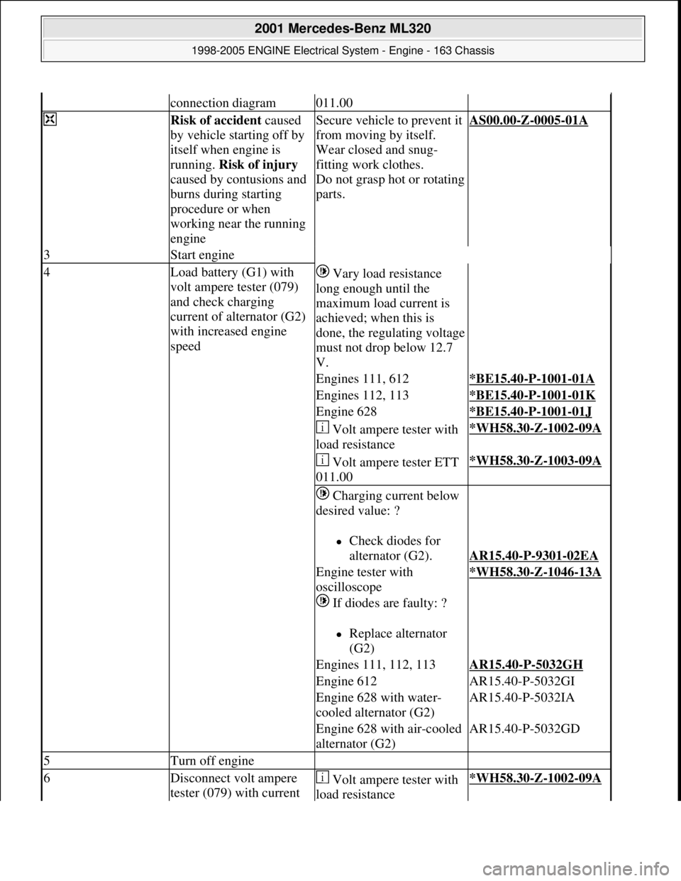
4Load battery (G1) with
volt ampere tester (079)
and check charging
current of alternator (G2)
with increased engine
speed Vary load resistance
long enough until the
maximum load current is
achieved; when this is
done, the regulating voltage
must not drop below 12.7
V.
Engines 111, 612*BE15.40-P-1001-01A
Engines 112, 113*BE15.40-P-1001-01K
Engine 628*BE15.40-P-1001-01J
Volt ampere tester with
load resistance*WH58.30-Z-1002-09A
Volt ampere tester ETT
011.00*WH58.30-Z-1003-09A
Charging current below
desired value: ?
Check diodes for
alternator (G2).
AR15.40-P-9301-02EA
Engine tester with
oscilloscope
If diodes are faulty: ?
Replace alternator
(G2)
*WH58.30-Z-1046-13A
Engines 111, 112, 113AR15.40-P-5032GH
Engine 612AR15.40-P-5032GI
Engine 628 with water-
cooled alternator (G2)AR15.40-P-5032IA
Engine 628 with air-cooled
alternator (G2)AR15.40-P-5032GD
5Turn off engine
6Disconnect volt ampere
tester (079) with current Volt ampere tester with
load resistance*WH58.30-Z-1002-09A
2001 Mercedes-Benz ML320
1998-2005 ENGINE Electrical System - Engine - 163 Chassis
me
Saturday, October 02, 2010 3:18:54 PMPage 58 © 2006 Mitchell Repair Information Company, LLC.
Page 2214 of 4133
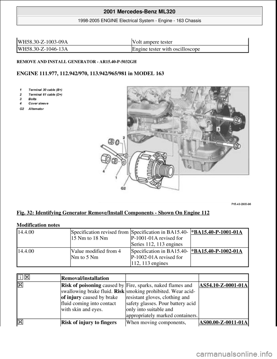
REMOVE AND INSTALL GENERATOR - AR15.40-P-5032GH
ENGINE 111.977, 112.942/970, 113.942/965/981 in MODEL 163
Fig. 32: Identifying Generator Remove/Install Components
- Shown On Engine 112
Modification notes
WH58.30-Z-1003-09AVolt ampere tester
WH58.30-Z-1046-13AEngine tester with oscilloscope
14.4.00Specification revised from
15 Nm to 18 NmSpecification in BA15.40-
P-1001-01A revised for
Series 112, 113 engines*BA15.40-P-1001-01A
14.4.00Value modified from 4
Nm to 5 NmSpecification in BA15.40-
P-1002-01A revised for
112, 113 engines*BA15.40-P-1002-01A
Removal/installation
Risk of poisoning caused by
swallowing brake fluid. Risk
of injury caused by brake
fluid coming into contact
with skin and eyes.Fire, sparks, naked flames and
smoking prohibited. Wear acid-
resistant gloves, clothing and
safety glasses. Pour battery acid
only into suitable and
appropriately marked containers.AS54.10-Z-0001-01A
Risk of injury to fingers When moving components, AS00.00-Z-0011-01A
2001 Mercedes-Benz ML320
1998-2005 ENGINE Electrical System - Engine - 163 Chassis
me
Saturday, October 02, 2010 3:18:54 PMPage 60 © 2006 Mitchell Repair Information Company, LLC.
Page 2215 of 4133
being jammed or squeezed
when removing and
installing or aligning hoods,
doors, trunk lid/tailgate or
sliding roof.ensure that no body parts or
limbs are within the operating
range of moving parts.
1Open engine hoodModel 163.136/154 /172 #A up
to 145272,
Model 163.136 /154 /172 #X up
to 708318AR88.40-P-1000GH
Model 163.136 /154 /172 #A as
of 145273,
Model 163.136 /154 /172 #X
from 708319,
Model
163.113/128 /157 /174 /175AR88.40-P-1000GI
2Disconnect battery ground
line Insulate cable lug of ground
line for protection against
unintentional contact of
disconnected ground line.AR54.10-P-0003A
Notes on batteryAll modelsAH54.10-P-0001-
01A
3Remove air cleaner housing Installation: Apply liquid
lubricant to the mounting
rubbers and to the connection to
the air hose.
Lubricant
*BR00.45-Z-1002-
06A
4.1Remove engine trim panel Engine 112, 113 only.
Pull the engine cover
vertically upwards and detach it
from the cylinder head covers.
5Slacken poly V-belt Do not remove the poly-V-
belt!
Engine 111AR13.22-P-1202A
Engine 603.931/972,
Engine 113.942AR13.22-P-1202B
Engine 113.981/965AR13.22-P-1202BA
6Disconnect electrical line
circuit 30 (B+) (1) and
electrical line circuit 61 (D+)
(2) On engine 112, 113 take off
cover sleeve (4).
*BA15.40-P-1001-
01A
*BA15.40-P-1002-
01A
7Unscrew bolts (3) of the
generator (G2) *BA15.40-P-1003-
01A
8Take out generator (G2)
9Install in the reverse
2001 Mercedes-Benz ML320
1998-2005 ENGINE Electrical System - Engine - 163 Chassis
me
Saturday, October 02, 2010 3:18:54 PMPage 61 © 2006 Mitchell Repair Information Company, LLC.
Page 2224 of 4133
Fig. 43: Generator Connection Diagram - Model 210
1. Connect DC clip-on probe (065) from engine tester with oscilloscope (030) to positive pole of battery
(G1)
2. Start engine.
3. Switch on low beam.
4. Assess diode harmonics at 3000 rpm (engine speed).
In this test it is not possible to assess the exciter diodes.
Fig. 44: Identifying Harmonics
- Negative Diode Defective
2001 Mercedes-Benz ML320
1998-2005 ENGINE Electrical System - Engine - 163 Chassis
me
Saturday, October 02, 2010 3:18:55 PMPage 70 © 2006 Mitchell Repair Information Company, LLC.
Page 2230 of 4133

1.1
Unscrew bolts at rear of 2/3 seat bench and
raise rear of seat bench
Up to VIN A145272, X708318.
1.2
Remove covers at seat frame of 60% bench
seat
As of VIN A145273, X708319.
AR91.12-P-1100GH
Only remove the covers which are
identified in the document with A, D and E.
2.1
Fold 60% bench seat forward into footwell
As of VIN A145273, X708319. See
operator's manual.
3.1
Pull floor covering below rear seat mounting
bracket (1) of 60% seat forward
Carefully pull floor covering forward under
the seat console to prevent it from tearing.
As of VIN A145273, X708319.
4.1
Pull the floor covering forward under the front
corner of the left C-pillar cover (2)
Carefully pull the floor covering forward
under the cover to prevent it from tearing.
As of VIN A145273, X708319.
5
Cut into floor covering directly behind seat
retaining cable (3)
Ensure that the wiring harness (4) is not
damaged when cutting the floor covering.
As of VIN A145273, X708319. Broken
line marks the cut.
6
Fold floor mat back
Do not crease floor mat!
Fold floor mat back far enough to provide
access to cap (84) between body and fuel
pump.
7
Remove end cover (84) of body
Installation:
Replace cap and insert with
new sealing compound.
Cap (84) is sealed in with body sealer.
Heat with hot air blower to make it easier to
remove.
8
Seal fuel return line (90/11)
Pliers
*163589003700
9
Connect extraction hose (90/14) with adapter
hose to connection for fuel return line (90/11)
Extraction hose
*168589009000
Adapter hose
*163589009100
10
Connect ground cable (90/10) of extraction
pump ground terminal vehicle battery
Pumping out
11
Pump fuel out into safety container using
extraction pump
*BF47.10-P-1001-01A
*WH58.30-Z-1001-16A
12
Install in the reverse order
Fuel tank
Number
Designation
Models
163.113/
136/154/
172 up to
31.08.01
Models
163.113/
136/154/
172 as of
01.09.01
Models
163.157/
175
Model
163.128
Model
163.174
BF47.10-P-1001-01A
Fuel tank capacity
Total capacity
Liter
72838393
Reserve capacity
Liter
10121212
Copyright DaimlerChrysler AG 28.05.2006 CD-Ausgabe G/10/04 . This WIS print-out will not be recorde
d by Modification services.
Page 2