1997 MERCEDES-BENZ ML430 battery
[x] Cancel search: batteryPage 2441 of 4133
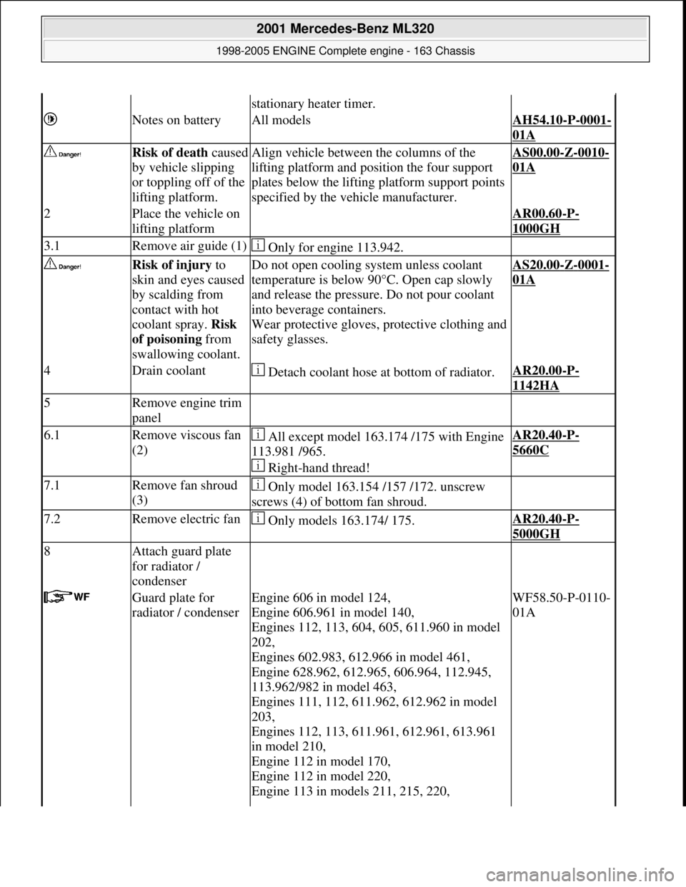
stationary heater timer.
Notes on batteryAll modelsAH54.10-P-0001-
01A
Risk of death caused
by vehicle slipping
or toppling off of the
lifting platform.Align vehicle between the columns of the
lifting platform and pos ition the four support
plates below the lifti ng platform support points
specified by the vehicle manufacturer.AS00.00-Z-0010-
01A
2Place the vehicle on
lifting platform AR00.60-P-
1000GH
3.1Remove air guide (1) Only for engine 113.942.
Risk of injury to
skin and eyes caused
by scalding from
contact with hot
coolant spray. Risk
of poisoning from
swallowing coolant.Do not open cooling system unless coolant
temperature is below 90° C. Open cap slowly
and release the pressure. Do not pour coolant
into beverage containers.
Wear protective gloves, pr otective clothing and
safety glasses.AS20.00-Z-0001-
01A
4Drain coolant Detach coolant hose at bottom of radiator.AR20.00-P-
1142HA
5Remove engine trim
panel
6.1Remove viscous fan
(2) All except model 163.174 /175 with Engine
113.981 /965.
Right-hand thread!AR20.40-P-
5660C
7.1Remove fan shroud
(3) Only model 163.154 /157 /172. unscrew
screws (4) of bottom fan shroud.
7.2Remove electric fan Only models 163.174/ 175.AR20.40-P-
5000GH
8Attach guard plate
for radiator /
condenser
Guard plate for
radiator / condenserEngine 606 in model 124,
Engine 606.961 in model 140,
Engines 112, 113, 604, 605, 611.960 in model
202,
Engines 602.983, 612.966 in model 461,
Engine 628.962, 612.965, 606.964, 112.945,
113.962/982 in model 463,
Engines 111, 112, 611.962, 612.962 in model
203,
Engines 112, 113, 611.961, 612.961, 613.961
in model 210,
Engine 112 in model 170,
Engine 112 in model 220,
Engine 113 in models 211, 215, 220, WF58.50-P-0110-
01A
2001 Mercedes-Benz ML320
1998-2005 ENGINE Complete engine - 163 Chassis
me
Saturday, October 02, 2010 3:17:57 PMPage 85 © 2006 Mitchell Repair Information Company, LLC.
Page 2453 of 4133
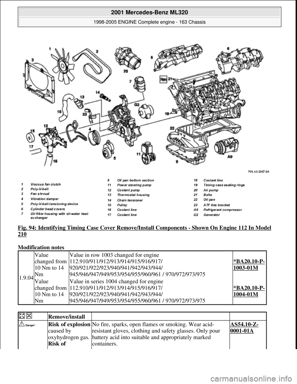
Fig. 94: Identifying Timing Case Cover Remove/Install Components - Shown On Engine 112 In Model
210
Modification notes
1.9.04
Value
changed from
10 Nm to 14
NmValue in row 1003 changed for engine
112.910/911/912/913/914/915/916/917/
920/921/922/923/940/941/942/943/944/
945/946/947/949/953/954/955/960/961 / 970/972/973/975
*BA20.10-P-
1003-01M
Value
changed from
10 Nm to 14
NmValue in series 1004 changed for engine
112.910/911/912/913/914/915/916/917/
920/921/922/923/940/941/942/943/944/
945/946/947/949/953/954/955/960/961 / 970/972/973/975
*BA20.10-P-
1004-01M
Remove/install
Risk of explosion
caused by
oxyhydrogen gas.
Risk of No fire, sparks, open fl ames or smoking. Wear acid-
resistant gloves, clothing and safety glasses. Only pour
battery acid into suitable and appropriately marked
containers.AS54.10-Z-
0001-01A
2001 Mercedes-Benz ML320
1998-2005 ENGINE Complete engine - 163 Chassis
me
Saturday, October 02, 2010 3:17:57 PMPage 97 © 2006 Mitchell Repair Information Company, LLC.
Page 2454 of 4133
poisoning and
caustic burns
caused by
swallowing
battery acid. Risk
of injury caused
by burns to skin
and eyes from
battery acid or
when handling
damaged lead-
acid batteries
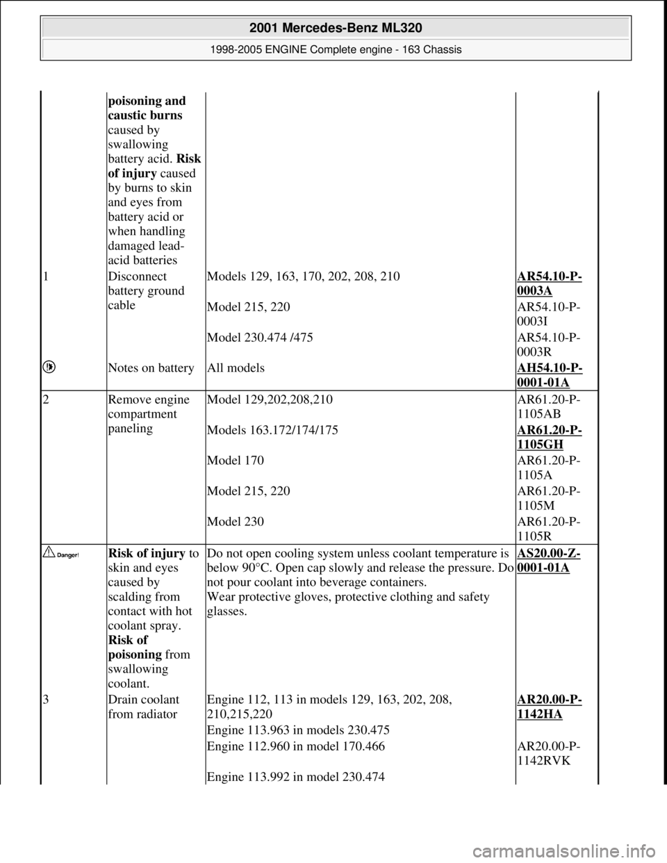
1Disconnect
battery ground
cableModels 129, 163, 170, 202, 208, 210AR54.10-P-
0003A
Model 215, 220AR54.10-P-
0003I
Model 230.474 /475AR54.10-P-
0003R
Notes on batteryAll modelsAH54.10-P-
0001-01A
2Remove engine
compartment
panelingModel 129,202,208,210AR61.20-P-
1105AB
Models 163.172/174/175AR61.20-P-
1105GH
Model 170AR61.20-P-
1105A
Model 215, 220AR61.20-P-
1105M
Model 230AR61.20-P-
1105R
Risk of injury to
skin and eyes
caused by
scalding from
contact with hot
coolant spray.
Risk of
poisoning from
swallowing
coolant.Do not open cooling system unless coolant temperature is
below 90°C. Open cap slowly and release the pressure. Do
not pour coolant into beverage containers.
Wear protective gloves, protec tive clothing and safety
glasses.
AS20.00-Z-
0001-01A
3Drain coolant
from radiatorEngine 112, 113 in models 129, 163, 202, 208,
210,215,220AR20.00-P-
1142HA
Engine 113.963 in models 230.475
Engine 112.960 in model 170.466AR20.00-P-
1142RVK
Engine 113.992 in model 230.474
2001 Mercedes-Benz ML320
1998-2005 ENGINE Complete engine - 163 Chassis
me
Saturday, October 02, 2010 3:17:57 PMPage 98 © 2006 Mitchell Repair Information Company, LLC.
Page 2601 of 4133

1.1
Unscrew bolts at rear of 2/3 seat bench and
raise rear of seat bench
Up to VIN A145272, X708318.
1.2
Remove covers at seat frame of 60% bench
seat
As of VIN A145273, X708319.
AR91.12-P-1100GH
Only remove the covers which are
identified in the document with A, D and E.
2.1
Fold 60% bench seat forward into footwell
As of VIN A145273, X708319. See
operator's manual.
3.1
Pull floor covering below rear seat mounting
bracket (1) of 60% seat forward
Carefully pull floor covering forward under
the seat console to prevent it from tearing.
As of VIN A145273, X708319.
4.1
Pull the floor covering forward under the front
corner of the left C-pillar cover (2)
Carefully pull the floor covering forward
under the cover to prevent it from tearing.
As of VIN A145273, X708319.
5
Cut into floor covering directly behind seat
retaining cable (3)
Ensure that the wiring harness (4) is not
damaged when cutting the floor covering.
As of VIN A145273, X708319. Broken
line marks the cut.
6
Fold floor mat back
Do not crease floor mat!
Fold floor mat back far enough to provide
access to cap (84) between body and fuel
pump.
7
Remove end cover (84) of body
Installation:
Replace cap and insert with
new sealing compound.
Cap (84) is sealed in with body sealer.
Heat with hot air blower to make it easier to
remove.
8
Seal fuel return line (90/11)
Pliers
*163589003700
9
Connect extraction hose (90/14) with adapter
hose to connection for fuel return line (90/11)
Extraction hose
*168589009000
Adapter hose
*163589009100
10
Connect ground cable (90/10) of extraction
pump ground terminal vehicle battery
Pumping out
11
Pump fuel out into safety container using
extraction pump
*BF47.10-P-1001-01A
*WH58.30-Z-1001-16A
12
Install in the reverse order
Fuel tank
Number
Designation
Models
163.113/
136/154/
172 up to
31.08.01
Models
163.113/
136/154/
172 as of
01.09.01
Models
163.157/
175
Model
163.128
Model
163.174
BF47.10-P-1001-01A
Fuel tank capacity
Total capacity
Liter
72838393
Reserve capacity
Liter
10121212
Copyright DaimlerChrysler AG 28.05.2006 CD-Ausgabe G/10/04 . This WIS print-out will not be recorde
d by Modification services.
Page 2
Page 2606 of 4133
AR47.10-P-4001GH
Emptying, filling the fuel tank
11.3.97
Model
163.136 with engine 111.977
Model
163.154 with engine 112.942
Model
163.157 with engine 112.970
Model
163.172 with engine 113.942
Model
163.174 with engine 113.981
Model
163.175 with engine 113.965
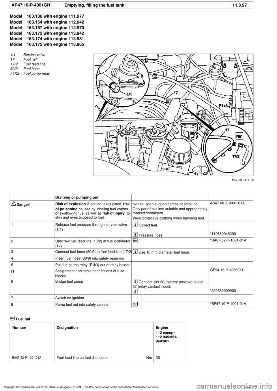
P47.10-0411-06
1/1
Service valve
17
Fuel rail
17/2
Fuel feed line
80/9
Fuel hose
F1K3
Fuel pump relay
Draining or pumping out
Danger!
Risk of explosion
if ignition takes place,
risk
of poisoning
caused by inhaling fuel vapors
or swallowing fuel as well as
risk of injury
to
skin and eyes exposed to fuel.
No fire, sparks, open flames or smoking.
Only pour fuels into suitable and appropriately
marked containers.
Wear protective clothing when handling fuel.
AS47.00-Z-0001-01A
1
Release fuel pressure through service valve
(1/1)
Collect fuel.
Pressure hose
*119589046300
2
Unscrew fuel feed line (17/2) at fuel distributor
(17)
*BA07.52-P-1001-01A
3
Connect fuel hose (80/9) to fuel feed line (17/2)
Use 10 mm diameter fuel hose.
4
Insert fuel hose (80/9) into safety reservoir
5
Pull fuel pump relay (F1k3) out of relay holder
n
Assignment and cable connections of fuse
blocks
GF54.15-P-1255GH
6
Bridge fuel pump
Connect slot 30 (battery positive) to slot
87 (relay contact input).
*220589009900
7
Switch on ignition
8
Pump fuel out into safety canister
*BF47.10-P-1001-01A
Fuel rail
Number
Designation
Engine
112 except
112.945/951/
960/961
BA07.52-P-1001-01A
Fuel feed line on fuel distributor
Nm
38
Copyright DaimlerChrysler AG 28.05.2006 CD-Ausgabe G/10/04 . This WIS print-out will not be recorde
d by Modification services.
Page 1
Page 2646 of 4133
1998-2005 GENINFO
Overall vehicle - 163 Chassis
GENERAL INFORMATION
NOTES ON SELF-LOCKING NUTS AND BOLTS - AH00.00-N-0001-01A
All models
Important repair information
Bolts with locking splines, micro-encapsulated bolts and self-locking nuts must always be replaced after
being used once.
There is an increased risk of injury when unscrewing micro-encapsulated bolts due to the sudden breakaway
torque.
Before new micro-encapsulated bolts are screwed in, the mating thread must be re-cut in order to remove all the
residue of the old bolt locking compound.
MEASURES FOR PREVENTING DAMAGE TO VEHICLES OR COMPONENTS WHEN PERFORMING ARC WELDING
WORK - AH00.00-N-0005-01A
All models
The following measures must be taken before welding in order to prevent damage to various vehicle
components:
1 Have fire extinguishers at the ready.
2 The negative terminal of the battery must be disconnected and covered up.
3 In vehicle with airbags the red, 12-pin test connection/plug-in connection must be disconnected no
sooner than two seconds after the battery has been disconnected (risk of unwanted activation).
6 Attach protective shields to prevent flying sparks and radiated heat in endangered areas.
7 Do not touch electronics housings or electrical cables with the welding electrode or the welder's ground
connection.
8 If two parts are being welded together, both parts must be attached to the welder's negative clamp.
9 Make direct connection between the electrical welder's ground connection and the part being welded.
Ensure that there are no electrically insulating parts between the ground connection and the welding
point.
10 Protect or remove any parts that are sensitive to heat such as plastic cables.
11 Remove electrical cables that are laid in cavities and/or pipelines, covered containers and electrical
components from the danger area before welding.
12 If possible, the points where the welded part is being attached to the vehicle and the ground terminal is
attached to the electrical welder must be bare; remove all traces of paint, corrosion, oil, grease and
2004 Mercedes-Benz ML350
1998-2005 GENINFO Overall vehicle - 163 Chassis
2004 Mercedes-Benz ML350
1998-2005 GENINFO Overall vehicle - 163 Chassis
me
Saturday, October 02, 2010 3:47:43 PMPage 1 © 2006 Mitchell Repair Information Company, LLC.
me
Saturday, October 02, 2010 3:48:01 PMPage 1 © 2006 Mitchell Repair Information Company, LLC.
Page 2853 of 4133
Warning threshold (in days)
With the HHT it is possible to set a warning threshold of between 5 and 30 days for the remaining time, with a
stepwidth of one day. The basic setting is 30 days.
Display of remaining time
The remaining time is always only displayed in those cases where the following condition is met:
Remaining time (in days) x 40 < remaining distance (in km), and the warning threshold is reached.
The remaining time is displayed in the following cases:
automatically, after 5 s start switch in position 2 or driving, if the warning threshold is reached:
The service symbol and the readout "SERVICE IN ... DAYS" appears for 10 seconds. (On vehicles not
fitted with multifunction display, the current remaining time, the service and the clock symbol appear.)
automatically, after 5 s start switch in position 2 or driving, if the remaining time is exceeded:
The service symbol and the readout "DAYS ... EXCEEDED" appears for 30 s (for 10 s up to mid-July
97). (On vehicles not fitted with multifunction display, the service and the clock symbol appear. The
"remaining time" is displayed with a negative sign (minus sign). The readout flashes in this case.)
After the display reaches the maximum readout of -730 days, the readout remains at this figure! The
readout is displayed with a resolution of 1 day.
As of approx. 06.97 a brief warning signal sounds in addition.
at driver request. The readout is then displayed, as above, for 10 s.
If a speed limit is set at the cruise control, this speed limit is displayed for a short moment before the
ASSYST display.
If certain measured values are not supplied to the ASSYST, e.g. because of failure of a sensor, it switches to
stored substitute values. An appropriate entry is then made in the fault memory of the particular control module.
If the power supply fails, the data are retained. The times without operating voltage (battery disconnected) are
not recorded, however! They can be retroactively included, however, with the HHT.
Active service system
(ASSYST) operating
informationEngine with oil sensor
(e.g. 112, 113, 611)GF00.20-P-0003-01A
Model 210 as of 01.03.97
with engines 111, 602,
604, 605, 606
Model 129, 140, 170, 202 GF00.20-P-0003-01B
2004 Mercedes-Benz ML350
1998-2005 GENINFO Overall vehicle - 163 Chassis
me
Saturday, October 02, 2010 3:47:47 PMPage 208 © 2006 Mitchell Repair Information Company, LLC.
Page 2873 of 4133
Restrain long hair by wearing an appropriate head cover.
Operate roller dynamometers only within the prescribed capacity limits.
Ensure that all persons remain outside of the hazard zone of rotating wheels, shafts and dynamometer
rollers when the dynamometer is in or ready for operation.
During testing, the driver's seat may only be vacated in case of emergency.
When not in use, protect roller dynamometers from unauthorized use by locking the main switch.
If the roller dynamometer used has an integrated workpit, the pit must be sealed off after use.
RISK OF DEATH CAUSED BY CONTACT WITH PARTS CONDUCTING HIGH VOLTAGES. - AS00.00-Z-0020-01A
Do not touch parts which conduct high voltages. Persons who wear electronic implants (e.g. heart
pacemakers) must not perform any work on such components.
Risk of death caused by electric shock
Electric shocks can cause fibrillation of the heart or even cardiac arrest. The effects of an electric shock may
sometimes first appear after several minutes have gone by; for this reason always seek medical attention.
Safety instructions/precautions
Persons who wear electronic implants (e.g. heart pacemakers) must not carry out any work on such
components.
Do not touch parts which conduct high voltages.
When working on such components, for example:
connecting and disconnecting electrical components
replacing parts
connecting test equipment
it is first of all necessary to disconnect the ground cable from the battery.
RISK OF DEATH CAUSED BY COMING INTO CONTACT WITH COMPONENTS OF A 220 V SYSTEM - AS00.00-Z-0021-
01A
Do not touch voltage conducting parts in of a 220 V system
Risk of death caused by electric shock
Risk of death caused by coming into contact with electrical parts of the 220 V system. Electric shocks can cause
fibrillation of the heart or even cardiac arrest. It may also take several minutes for the consequences of an
electric shock to show themselves; for this reason
always contact a doctor.
Risk of injury caused by burns
2004 Mercedes-Benz ML350
1998-2005 GENINFO Overall vehicle - 163 Chassis
me
Saturday, October 02, 2010 3:47:48 PMPage 228 © 2006 Mitchell Repair Information Company, LLC.