1997 MERCEDES-BENZ ML430 battery
[x] Cancel search: batteryPage 3226 of 4133
A/C EVAPORATOR HOUSING UNIT
Removal & Installation
1. Drain engine coolant. Remove coolant expansion reservoir nuts, disconnect hoses and remove reservoir.
Discharge A/C system, using approved refrigerant recovery/recycling equipment.
2. Remove expansion valve self-locking nut and discard. See Fig. 5
. Disconnect refrigerant lines from
expansion valve. Plug exposed refrigerant lines to protect A/C system from moisture and debris.
3. Remove instrument panel. See INSTRUMENT PANEL
. Remove Electronic Transmission Control
(ETC) module. See Fig. 4
. Disconnect air mix flap actuator connector.
4. Disconnect recirculated air flap element. Disconnect evaporator temperature sensor. Disconnect blower
motor resistor and blower motor connectors. Remove A/C push button control module. Release wiring
harness.
5. Remove insulating mat. See Fig. 5
. Disconnect water drain hose from bottom of A/C housing. Release
A/C housing-to-air distributor clips and remove A/C housing upward. To install, reverse removal
procedure. Recode radio. See RECODING RADIO
under PROGRAMMING. WARNING:To avoid injury from accidental air bag deployment, read and carefully
follow all SERVICE PRECAUTIONS and DISABLING & ACTIVATING AIR
BAG SYSTEM procedures in AIR BAG SYSTEM SAFETY article in
GENERAL SERVICING.
CAUTION: Before disconnecting battery, obtain 5-digit radio security code from
vehicle owner. Radio will be disabled until properly recoded.
2001 Mercedes-Benz ML320
2000-01 MANUAL A/C-HEATER SYSTEMS ML 320, ML 430 & ML 55
me
Saturday, October 02, 2010 3:25:10 PMPage 15 © 2006 Mitchell Repair Information Company, LLC.
Page 3227 of 4133
Fig. 4: Removing Evaporator Housing Unit
Courtesy of MERCEDES-BENZ OF NORTH AMERICA.
A/C MIX FLAP ACTUATOR
Removal & Installation
Remove instrument panel. See INSTRUMENT PANEL . Disconnect air mix flap actuator connector. Remove
3 screws and remove air mix flap actuator. To install reverse removal procedure.
A/C PUSH BUTTON CONTROL MODULE
Removal & Installation
Disconnect negative battery cable. Remove A/C push button control panel. See A/C PUSH BUTTON
CONTROL PANEL . Remove 4 A/C push button control module screws and remove control module from
2001 Mercedes-Benz ML320
2000-01 MANUAL A/C-HEATER SYSTEMS ML 320, ML 430 & ML 55
me
Saturday, October 02, 2010 3:25:10 PMPage 16 © 2006 Mitchell Repair Information Company, LLC.
Page 3228 of 4133
A/C housing. Disconnect control module connector. To install reverse removal procedure. Recode 5-digit radio
security code. Using HHT, check for DTC and erase, and set clock.
A/C PUSH BUTTON CONTROL PANEL
Removal & Installation
1. Obtain 5-digit radio security code from vehicle owner. Disconnect negative battery cable. Using radio
removal plates, remove radio. Disconnect electrical connectors.
2. Remove instrument panel center section. Remove 4 A/C control panel screws and remove control panel.
Release pull cables and disconnect connectors. To install, reverse removal procedure. Recode radio. See
RECODING RADIO
under PROGRAMMING.
BLOWER MOTOR
Removal & Installation
Remove passenger-side instrument panel under cover. Remove blower motor mounting screws from A/C
housing unit. Disconnect blower motor connector and remove blower motor. To install, reverse removal
procedure.
COMPRESSOR
Removal & Installation
1. Discharge A/C system, using approved refrigerant recovery/recycling equipment. Remove accessory
drive belt. Disconnect low pressure refrigerant line from compressor. Discard "O" rings. Plug exposed
openings to protect A/C system from debris and moisture.
2. Disconnect high pressure refrigerant line from compressor. Discard "O" rings. Plug exposed openings to
protect A/C system from debris and moisture. Disconnect electrical connector. Remove compressor
mounting bolts.
3. Raise and support vehicle. Remove compressor from under vehicle without spilling refrigerant oil. To
install, reverse removal procedure. Ensure refrigerant oil quantity in compressor is correct. See
COMPRESSOR REFRIGERANT OIL CHECKING under GENERAL SERVICING. Tighten bolts to
specification. See TORQUE SPECIFICATIONS
.
CONDENSER
Removal & Installation
1. Discharge A/C system, using approved refrigerant recovery/recycling equipment. Remove cooling fans.
See COOLING FANS
. Disconnect refrigerant line from receiver-drier. See Fig. 5 . Discard "O" rings.
2. Plug exposed openings to protect A/C system from debris and moisture. Remove refrigerant line from
condenser. Remove radiator upper rubber seal. See Fig. 6
. Remove condenser upper mounting screws.
Lift condenser upward and remove. NOTE: Each time A/C compressor is removed and installed, receiver-drier must be
replaced.
2001 Mercedes-Benz ML320
2000-01 MANUAL A/C-HEATER SYSTEMS ML 320, ML 430 & ML 55
me
Saturday, October 02, 2010 3:25:10 PMPage 17 © 2006 Mitchell Repair Information Company, LLC.
Page 3232 of 4133
Fig. 6: Removing Cooling Fans & Condenser
Courtesy of MERCEDES-BENZ OF NORTH AMERICA.
COOLING FANS
Removal & Installation
Remove headlight units. Remove upper frame crossmember, release hood release control cable and remove
crossmember. See Fig. 6
. Remove 2 cooling fans frame bolts on radiator. Disconnect cooling fan connector.
Release outside temperature sensor wiring harness. Pull up on cooling fan and remove. To install, reverse
removal procedure. Ensure cooling fan bottom guides are properly seated in lower mounts.
EVAPORATOR
Removal & Installation
Remove A/C housing unit. See A/C HOUSING UNIT . Remove expansion valve. See Fig. 5 . Discard "O"
rings. Disassemble A/C housing unit. Remove evaporator. Remove evaporator temperature sensor. To install,
reverse removal procedure. Use NEW "O" rings lubricated with refrigerant oil. If installing a new or repair
evaporator, add 1.35 ounces of NEW refrigerant oil to evaporator.
EXPANSION VALVE
Removal & Installation
1. Discharge A/C system, using approved refrigerant recovery/recycling equipment. Without disconnecting
coolant hoses, remove coolant expansion reservoir and set aside. Remove refrigerant line bracket and
loosen clamps. See Fig. 5
. Pull refrigerant lines out of expansion valve.
2. Remove expansion valve self-locking nut and discard. Remove expansion valve. Discard "O" rings. To
install, reverse removal procedure. Use NEW "O" rings lubricated with refrigerant oil. Tighten NEW self-
locking nut to specification. See TORQUE SPECIFICATIONS
.
INSTRUMENT PANEL & INSTRUMENT PANEL CARRIER
Removal & Installation
1. Secure vehicle against rolling. Set transmission selector to "D" position. Obtain radio security code.
Disconnect negative battery cable. Remove driver-side air bag.
2. Place match marks on steering wheel and steering shaft. Remove steering wheel, upper steering column
covers and combination switch. Remove instrument cluster cover frame. Remove one instrument panel
lower section bolt.
3. Remove screws in footwell from left side of instrument panel bottom section. Remove instrument panel
center section. Remove 4 A/C control panel screws and remove control panel. See Fig. 1
. Release pull
cables and disconnect connectors.
4. Remove screws from center section. Remove glove box. Remove screws in footwell from right side of
instrument panel bottom section. Remove entry courtesy lights. Remove end covers and screws.
5. Release 4 "A" clips between instrument panel bottom section and upper section. See Fig. 7
. Release
parkin
g brake release cable from handle. With assistance, remove instrument panel bottom section.
2001 Mercedes-Benz ML320
2000-01 MANUAL A/C-HEATER SYSTEMS ML 320, ML 430 & ML 55
me
Saturday, October 02, 2010 3:25:10 PMPage 21 © 2006 Mitchell Repair Information Company, LLC.
Page 3341 of 4133
REST BUTTON, FUNCTION - GF83.40-P-2109-01GI
Function
Pressing the reset button ( ) on the AAC push-button control module (N22) switches on the residual engine
heat utilization system. When the engine is switched off, the residual heat heats the vehicle depending on the
temperature setting on the AAC push-button control panel (N22) and the ambient temperature in the vehicle
interior. The vehicle can be heated for approx. 30 min, with the engine switched off. The function is only
available with the ignition switched off or in position 1. If there is low voltage, the residual heat function is
automatically switched off.
The flaps are in automatic mode and the quantity of air is also automatically regulated.
The residual heat function is switched off,
if the electronic key is moved to position 2 in the starter switch,
after approx. 30 minutes,
if the battery voltage drops below 11V.
AUXILIARY FAN, FUNCTION - GF83.40-P-2115-01GH
Function
Depending on the refrigerant pressure and/or the coolant temperature the left auxiliary fan (M4m1), right
auxiliary fan (M4m2) are actuated.
The all-activity module (AAM) (N10) receives the coolant temperature from the coolant temperature sensor and
the refrigerant pressure from the refrigerant pressure sensor (B12).
The all-activity module (AAM) (N10) compares this input information with stored values and actuates the left
auxiliary fan (M4m1), right auxiliary fan (M4m2).
When the following values are indicated the left auxiliary fan (M4m1), right auxiliary fan (M4m2) are switched
on or off:
refrigerant pressure >16 bar = auxiliary fan ON
refrigerant pressure < 12 bar = auxiliary fan OFF
coolant temperature > 105°C = auxiliary fan ON
coolant temperature < 94°C = auxiliary fan OFF
AUXILIARY FAN, FUNCTION - GF83.40-P-2115-01GI
Function
Depending on the refrigerant pressure and/or the coolant temperature the left auxiliary fan (M4m1) and the right
auxiliary fan (M4m2) are actuated.
2001 Mercedes-Benz ML320
1998-2005 HVAC Climate Control - 163 Chassis
me
Saturday, October 02, 2010 3:23:16 PMPage 97 © 2006 Mitchell Repair Information Company, LLC.
Page 3347 of 4133
Whenever the system is opened, the fluid reservoir should be replaced because of the water which has
collected there in the meantime.
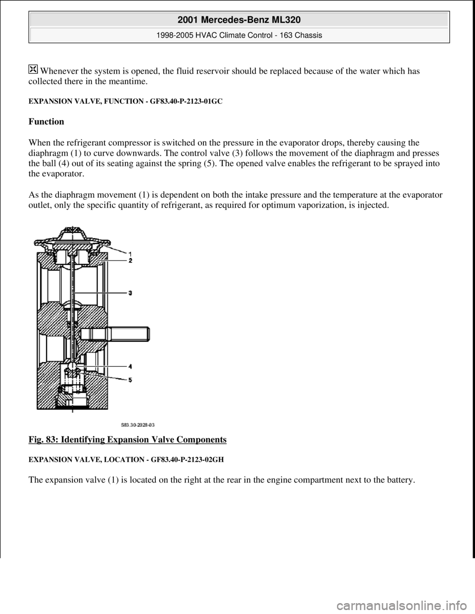
EXPANSION VALVE, FUNCTION - GF83.40-P-2123-01GC
Function
When the refrigerant compressor is switched on the pressure in the evaporator drops, thereby causing the
diaphragm (1) to curve downwards. The control valve (3) follows the movement of the diaphragm and presses
the ball (4) out of its seating against the spring (5). The opened valve enables the refrigerant to be sprayed into
the evaporator.
As the diaphragm movement (1) is dependent on both the intake pressure and the temperature at the evaporator
outlet, only the specific quantity of refrigerant, as required for optimum vaporization, is injected.
Fig. 83: Identifying Expansion Valve Components
EXPANSION VALVE, LOCATION - GF83.40-P-2123-02GH
The expansion valve (1) is located on the right at the rear in the engine compartment next to the battery.
2001 Mercedes-Benz ML320
1998-2005 HVAC Climate Control - 163 Chassis
me
Saturday, October 02, 2010 3:23:16 PMPage 103 © 2006 Mitchell Repair Information Company, LLC.
Page 3397 of 4133
OFF . To this end the system uses the residual heat of the engine. The residual engine heat is dissipated to the
coolant and routed through the heat exchanger with the aid of the heating water circulation pump. The air drawn
in by the blower motor is routed around the heat exchanger, whereby it is then warmed up. The heated air is
then routed over the air outlets into the passenger compartment.
The residual engine heat utilization system can only be used when the ignition is switched OFF.
Once the Rest push-button ( ) on the AAC push-button control module (N22) has been pressed the
following program sequence is run:
Blending air flaps are automatically controlled
Heating water circulation pump ON
The blower's control voltage is limited to a maximum value of 5 Volt.
End of program
Pressing the Rest push-button ( )
Timeout of 30 minutes period (repeated operation possible)
Protection against undervoltage at a battery voltage of less than 11 V (LED flashes)
Ignition ON
During the residual engine heat utilization function no function keys are accepted apart from the Rest push-
button ( ) and the set point adjusters.
SAFETY PRECAUTIONS
RISK OF EXPLOSION CAUSED BY WELDING OR SOLDERING WORK ON CLOSED AIR CONDITIONING SYSTEM.
RISK OF POISONING CAUSED BY INHALING OVERHEATED REFRIGERANT VAPORS. RISK OF INJURY TO SKIN AND
EYES CAUSED BY CONTACT WITH LIQUID REFRIGERANT. - AS83.00-Z-0001-01A
Never perform welding work on or near a closed air conditioning system. No smoking or open flames.
Wear safety glasses and protective gloves. Work only in well ventilated areas. Carry out repair work on
the air conditioning system circuit only after the system has been discharged.
Potential risks
Risk of explosion
When closed air conditionin
g systems (charged or empty) become heated, high pressures are produced that can
Rest push-button, location/task/function GF83.40-P-2148GI
Heating water circulation pump, location/task/ function GF83.20-P-2109GI
Heating system heat exchanger, location/ purpose/function GF83.20-P-2108GC
Blower motor, location/task/design/function GF83.10-P-2170GI
Blending air flap actuator, location/task/function GF83.57-P-2112GI
2001 Mercedes-Benz ML320
1998-2005 HVAC Climate Control - 163 Chassis
me
Saturday, October 02, 2010 3:23:17 PMPage 153 © 2006 Mitchell Repair Information Company, LLC.
Page 3413 of 4133
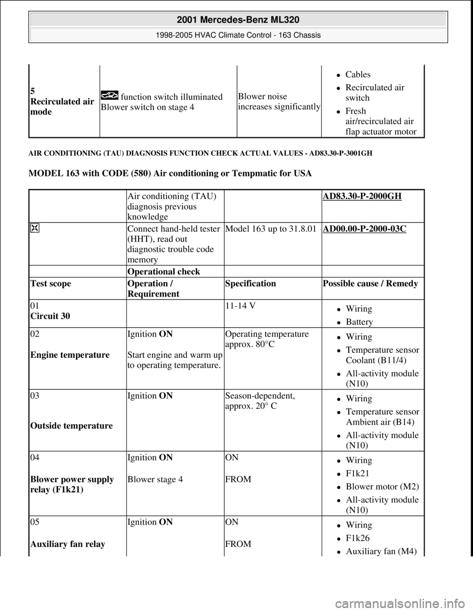
AIR CONDITIONING (TAU) DIAGNOSIS FUNCTION CHECK ACTUAL VALUES - AD83.30-P-3001GH
MODEL 163 with CODE (580) Air conditioning or Tempmatic for USA
5
Recirculated air
mode function switch illuminated
Blower switch on stage 4Blower noise
increases significantly
Cables
Recirculated air
switch
Fresh
air/recirculated air
flap actuator motor
Air conditioning (TAU)
diagnosis previous
knowledge AD83.30-P-2000GH
Connect hand-held tester
(HHT), read out
diagnostic trouble code
memoryModel 163 up to 31.8.01AD00.00-P-2000-03C
Operational check
Test scope Operation /
Requirement Specification Possible cause / Remedy
01
Circuit 30 11-14 VWiring
Battery
02Ignition ON Operating temperature
approx. 80°CWiring
Temperature sensor
Coolant (B11/4)
All-activity module
(N10)
Engine temperature Start engine and warm up
to operating temperature.
03Ignition ON Season-dependent,
approx. 20° CWiring
Temperature sensor
Ambient air (B14)
All-activity module
(N10)
Outside temperature
04Ignition ON ONWiring
F1k21
Blower motor (M2)
All-activity module
(N10)
Blower power supply
relay (F1k21) Blower stage 4FROM
05Ignition ON ONWiring
F1k26
Auxiliary fan (M4) Auxiliary fan relay FROM
2001 Mercedes-Benz ML320
1998-2005 HVAC Climate Control - 163 Chassis
me
Saturday, October 02, 2010 3:23:17 PMPage 169 © 2006 Mitchell Repair Information Company, LLC.