1997 MERCEDES-BENZ ML430 Oil filter housing
[x] Cancel search: Oil filter housingPage 2085 of 4133
AR01.30-P-5800MV
Remove/install cylinder head
22.7.98
ENGINE
112.942 in MODEL 163.154
ENGINE
112.970 in MODEL 163.157
ENGINE
113.942 in MODEL 163.172
ENGINE
113.981 in MODEL 163.174
ENGINE
113.965 in MODEL 163.175
P01.30-2032-06
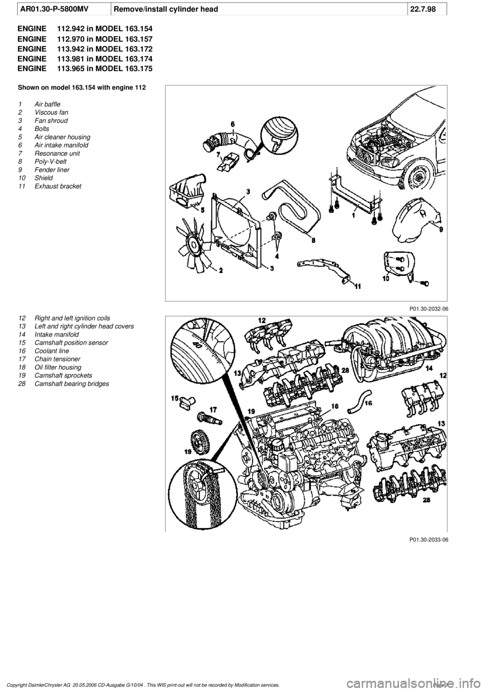
Shown on model 163.154 with engine 112
1
Air baffle
2
Viscous fan
3
Fan shroud
4
Bolts
5
Air cleaner housing
6
Air intake manifold
7
Resonance unit
8
Poly-V-belt
9
Fender liner
10
Shield
11
Exhaust bracket
P01.30-2033-06
12
Right and left ignition coils
13
Left and right cylinder head covers
14
Intake manifold
15
Camshaft position sensor
16
Coolant line
17
Chain tensioner
18
Oil filter housing
19
Camshaft sprockets
28
Camshaft bearing bridges
Copyright DaimlerChrysler AG 20.05.2006 CD-Ausgabe G/10/04 . This WIS print-out will not be recorde
d by Modification services.
Page 1
Page 2088 of 4133

16
Remove poly V-belt (8)
Installation:
Lock tensioning device with
a drift or pin (diameter 5 mm).
Model 163.154 /157 /172.
AR13.22-P-1202B
Model 163.174 /175.
AR13.22-P-1202BA
17
Detach the coolant line (16) at the cylinder
head on the left
6 mm socket hexagon
*WH58.30-Z-1001-06A
7 mm socket hexagon
*WH58.30-Z-1002-06A
18.1
Remove fender liner (9)
Only with engine 113.113.942 /965 / 981.
AR88.10-P-1300GH
19.1
Remove shield (10)
Only with engine 113.942 /965 /981.
20.1
Remove exhaust bracket (11)
Only with engine 113.942 /965 /981.
Support exhaust system.
21
Detach exhaust system at exhaust manifold
Installation:
On vehicles with engine
damage, the exhaust system must be
examined for swarfs before assembling and
any swarfs present must be removed, in order
to avoid consequential damage.
*BA14.10-P-1002-01B
22
Position crankshaft to 40° after ignition TDC
on cylinder 1
The engine must not be turned back;
otherwise the timing chain can get jammed.
AR05.10-P-6858V
Rotate engine at the crankshaft in running
direction until scribe mark 40° on pulley/
vibration damper corresponds with scribe
mark on timing case.
The grooves on the camshafts must be
pointing toward the inner V.
23
Lock camshafts with locating plates
Locating plate
*112589003200
Locating plate
*112589013200
24
Remove chain tensioner (17)
Model 163.154 /157 with engine 112.942/
970, model 163.172 with engine 113.942.
AR05.10-P-7800C
Model 163.174 /175 with engine 113.981/ 965.
AR05.10-P-7800CA
25.1
Remove oil filter housing (18) together with oil-
water heat exchanger
Engine 113.942.
AR18.20-P-3471B
Engine 112.942/970.
AR18.20-P-3471BA
26
Unscrew camshaft sprockets (19)
If camshaft sprockets are removed,
engine must no longer be cranked, otherwise
timing chain might jam.
Engine 113.942 /965 /981:
#
Tie timing chain tight on both camshaft
sprockets with tie straps.
Engine 112.942 /970:
#
Right-hand camshaft sprocket:
Tie timing chain tight on camshaft sprocket
with tie strap.
Left-hand camshaft sprocket:
Mark camshaft sprocket to timing chain and
remove camshaft sprocket.
It is not possible for the timing chain to
jump across at the crankshaft and balancing
shaft.
After installation:
#
Inspect basic position of camshafts.
AR05.10-P-6858V
If necessary after checking:
#
Set the basic position of camshafts
AR05.20-P-6020AU
Open-end wrench
*112589000100
Insertion tool
*112589010300
Torque wrench
*001589722100
*BA05.20-P-1001-01B
27
Remove camshaft bearing bridges (28)
Pay attention to slackening and tightening
pattern!
AR05.20-P-7103AU
28
Unscrew bolts, cylinder head
!
timing case
cover (20)
*BA01.40-P-1002-01C
Copyright DaimlerChrysler AG 20.05.2006 CD-Ausgabe G/10/04 . This WIS print-out will not be recorde
d by Modification services.
Page 4
Page 2093 of 4133
AR01.30-P-5800MV
Remove/install cylinder head
22.7.98
ENGINE
112.942 in MODEL 163.154
ENGINE
112.970 in MODEL 163.157
ENGINE
113.942 in MODEL 163.172
ENGINE
113.981 in MODEL 163.174
ENGINE
113.965 in MODEL 163.175
P01.30-2032-06
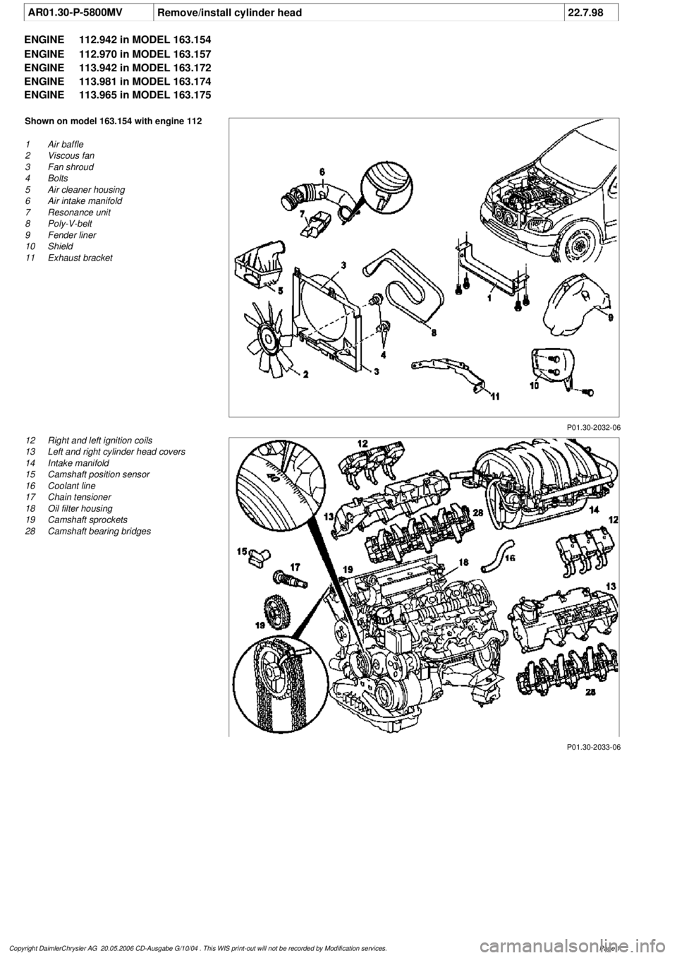
Shown on model 163.154 with engine 112
1
Air baffle
2
Viscous fan
3
Fan shroud
4
Bolts
5
Air cleaner housing
6
Air intake manifold
7
Resonance unit
8
Poly-V-belt
9
Fender liner
10
Shield
11
Exhaust bracket
P01.30-2033-06
12
Right and left ignition coils
13
Left and right cylinder head covers
14
Intake manifold
15
Camshaft position sensor
16
Coolant line
17
Chain tensioner
18
Oil filter housing
19
Camshaft sprockets
28
Camshaft bearing bridges
Copyright DaimlerChrysler AG 20.05.2006 CD-Ausgabe G/10/04 . This WIS print-out will not be recorde
d by Modification services.
Page 1
Page 2096 of 4133

16
Remove poly V-belt (8)
Installation:
Lock tensioning device with
a drift or pin (diameter 5 mm).
Model 163.154 /157 /172.
AR13.22-P-1202B
Model 163.174 /175.
AR13.22-P-1202BA
17
Detach the coolant line (16) at the cylinder
head on the left
6 mm socket hexagon
*WH58.30-Z-1001-06A
7 mm socket hexagon
*WH58.30-Z-1002-06A
18.1
Remove fender liner (9)
Only with engine 113.113.942 /965 / 981.
AR88.10-P-1300GH
19.1
Remove shield (10)
Only with engine 113.942 /965 /981.
20.1
Remove exhaust bracket (11)
Only with engine 113.942 /965 /981.
Support exhaust system.
21
Detach exhaust system at exhaust manifold
Installation:
On vehicles with engine
damage, the exhaust system must be
examined for swarfs before assembling and
any swarfs present must be removed, in order
to avoid consequential damage.
*BA14.10-P-1002-01B
22
Position crankshaft to 40° after ignition TDC
on cylinder 1
The engine must not be turned back;
otherwise the timing chain can get jammed.
AR05.10-P-6858V
Rotate engine at the crankshaft in running
direction until scribe mark 40° on pulley/
vibration damper corresponds with scribe
mark on timing case.
The grooves on the camshafts must be
pointing toward the inner V.
23
Lock camshafts with locating plates
Locating plate
*112589003200
Locating plate
*112589013200
24
Remove chain tensioner (17)
Model 163.154 /157 with engine 112.942/
970, model 163.172 with engine 113.942.
AR05.10-P-7800C
Model 163.174 /175 with engine 113.981/ 965.
AR05.10-P-7800CA
25.1
Remove oil filter housing (18) together with oil-
water heat exchanger
Engine 113.942.
AR18.20-P-3471B
Engine 112.942/970.
AR18.20-P-3471BA
26
Unscrew camshaft sprockets (19)
If camshaft sprockets are removed,
engine must no longer be cranked, otherwise
timing chain might jam.
Engine 113.942 /965 /981:
#
Tie timing chain tight on both camshaft
sprockets with tie straps.
Engine 112.942 /970:
#
Right-hand camshaft sprocket:
Tie timing chain tight on camshaft sprocket
with tie strap.
Left-hand camshaft sprocket:
Mark camshaft sprocket to timing chain and
remove camshaft sprocket.
It is not possible for the timing chain to
jump across at the crankshaft and balancing
shaft.
After installation:
#
Inspect basic position of camshafts.
AR05.10-P-6858V
If necessary after checking:
#
Set the basic position of camshafts
AR05.20-P-6020AU
Open-end wrench
*112589000100
Insertion tool
*112589010300
Torque wrench
*001589722100
*BA05.20-P-1001-01B
27
Remove camshaft bearing bridges (28)
Pay attention to slackening and tightening
pattern!
AR05.20-P-7103AU
28
Unscrew bolts, cylinder head
!
timing case
cover (20)
*BA01.40-P-1002-01C
Copyright DaimlerChrysler AG 20.05.2006 CD-Ausgabe G/10/04 . This WIS print-out will not be recorde
d by Modification services.
Page 4
Page 2193 of 4133
version FB6 with code ZS6, -
special protection version FB7
with code ZS7, additional battery
100 Ah incl. cutoff relay code E26.
Model 463.248 with: special
protection version, code 979, -
special protection version FB6,
code ZS6, -special protection
version FB7, code ZS7, -additional
battery 100 Ah including cutoff
relay, code E26.AR54.10-P-0003PM
3.1Unclip cover on front
side of engineModel 211, 215, 220, 230.475/476
4.1Remove engine cover
with integrated air filterExcept model 170.466,
203.065/076/265/276, 209.376/476
from 24.4.04, 211.076/276,
215.374, 220.074/174, 230.474,
463.270/271
The air filter is integrated in the
engine cover. Remove the engine
cover or the air filter housing by
pulling it from the cylinder head
covers vertically in the upward
direction.
4.2Remove air filter housingModel 170.466, 203.065/265,
211.076/276, 215.374,
220.074/174, 230.474AR09.10-P-1150SVK
Model 203.076 /276, 209.376 /476
from 24.4.04, 171.473AR09.10-P-1150AC
Model 463.270/271AR09.10-P-1150GX
5Unscrew screw (5/3) *BA15.10-P-1001-
04A
6Detach spark plug
connector (5/1) from the
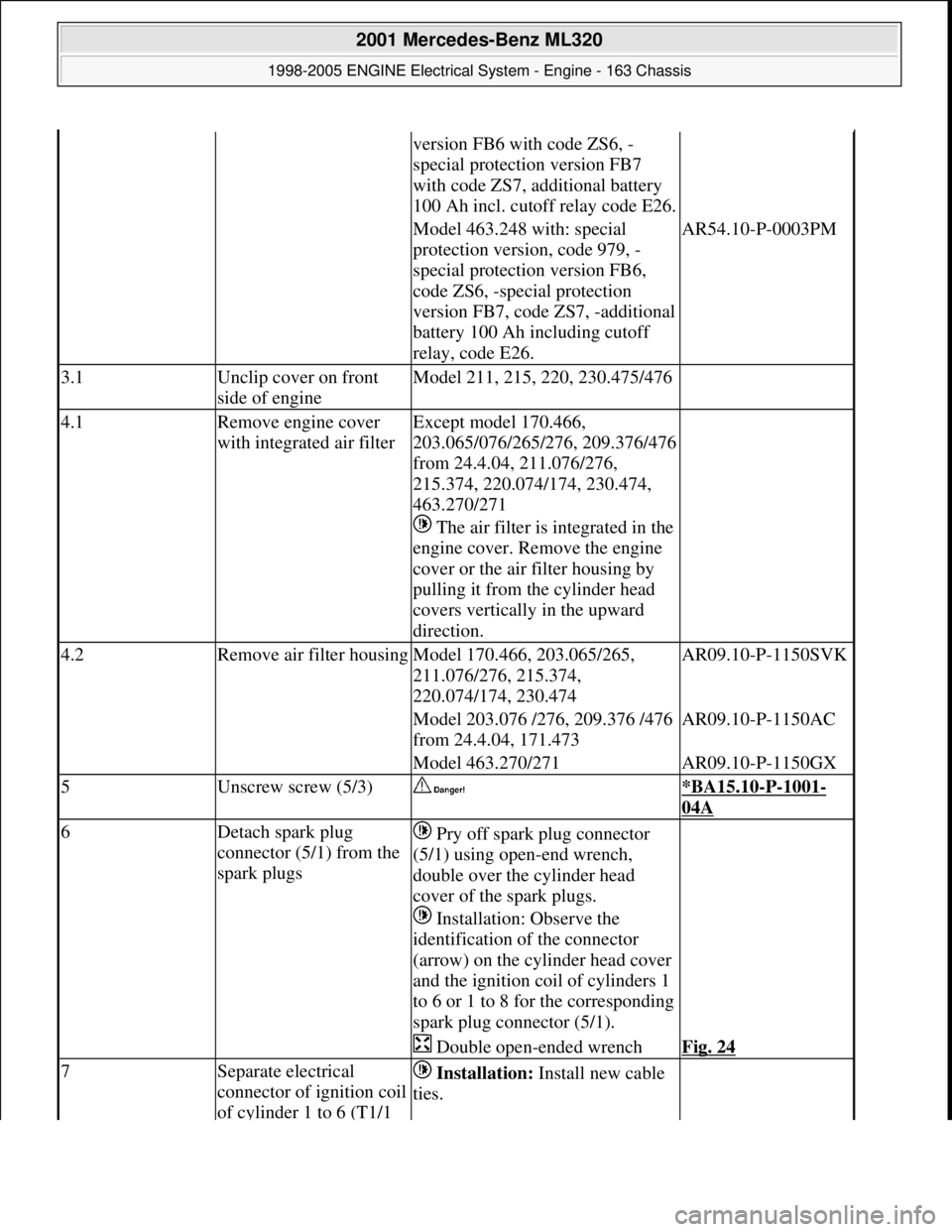
spark plugs Pry off spark plug connector
(5/1) using open-end wrench,
double over the cylinder head
cover of the spark plugs.
Installation: Observe the
identification of the connector
(arrow) on the cylinder head cover
and the ignition coil of cylinders 1
to 6 or 1 to 8 for the corresponding
spark plug connector (5/1).
Double open-ended wrenchFig. 24
7Separate electrical
connector of ignition coil
of cylinder 1 to 6 (T1/1 Installation: Install new cable
ties.
2001 Mercedes-Benz ML320
1998-2005 ENGINE Electrical System - Engine - 163 Chassis
me
Saturday, October 02, 2010 3:18:54 PMPage 39 © 2006 Mitchell Repair Information Company, LLC.
Page 2239 of 4133

AF07.00-P-9000B
Engine runs rough, surges or does not turn over
29.4.02
ENGINE
611 in MODEL 203, 202, 210
ENGINE
612 in MODEL 163, 203, 210, 209
ENGINE
613 in MODEL 210, 220
ENGINE
628 in MODEL 163, 220, 211
ENGINE
646 in MODEL 203, 211
ENGINE
647 in MODEL 211
ENGINE
648 in MODEL 220, 211
ENGINE
668 in MODEL 168
ENGINE
612, 628 in MODEL 463
Modification notes
23.3.01
Supersedes STIP 07.16-014 dated 11.12.00
Damage code
Cause
Remedy
07 206 D5
High-pressure pump
To verify whether high pressure pump is
damaged.
#
High pressure pump of common rail
injection system is damaged mechanically.
1
Remove/install/replace high pressure
pump.
When the high pressure pump of the common
rail injection system is damaged metal chips
and/or damage to the pump drive (timing
drive) can occur due to contamination of the
injection system components.
2
Turn high pressure pump by hand with
driver.
If mechanical resistance can be felt,
perform the following tests. Clarify additional
work with ESKULAB by specifying repair work:
#
3
Check driver of high pressure pump or
mount in sprocket for damage (visual
check).
If high pressure pump is locked:
#
4
Check timing
5
Check timing drive for damage.
In each case:
#
6
Remove/install/replace timing chain.
If timing deviates by a crankshaft angle of
more than 20 degrees (corresponding to one
tooth skipped):
#
7
Check pressure loss.
8
Open low pressure connection on high
pressure pump return (plastic line in
area of pressure regulator valve) and
check connection point in rail for chips.
If chips are present when checking
injection system:
#
9
Thoroughly clean all fuel low pressure
lines as well as feed and return lines.
Flush and blow out with compressed air.
10
Remove fuel preheater and fuel filter
with filter housing, replace.
Fuel preheater is only installed in models
202, 203 and 163.
11
Remove/install/replace fuel cooler at
vehicle and engine end.
Not installed in model 210 up to 6/99 and
model 168.
12
Remove fuel tank, replace.
On engine 628:
#
13
Remove/install/replace electric supply
pump.
14
Remove/install/replace injectors, rail
(including pressure regulation valve and
rail pressure sensor), high pressure
lines and injector leak oil rail.*
Copyright DaimlerChrysler AG 28.05.2006 CD-Ausgabe G/10/04 . This WIS print-out will not be recorde
d by Modification services.
Page 1
Page 2419 of 4133
lRemove/install
External torx setFig. 49
Torx bit setFig. 48
1Remove engine trim panel
2Remove air filter housing
(1).
3Remove resonance body (2)
4Remove the resonance tube
(3) with hot film mass air
flow sensor
At this time pull out the
hot film mass air flow
sensor plug.
Removal:
Pay attention to the
mounting projection of the
resonance tube (3)!
All except model 163 with
engine 113.942/981AR07.07-P-1454A
Model 163 with engine
113.942/981AR07.07-P-1454MV
5Unbolt dipstick guide tube
of automatic transmission
6Unbolt ignition coils (6, 7)
at cylinder head covers
AR15.12-P-2003A
*BA01.20
-P-1002-01E
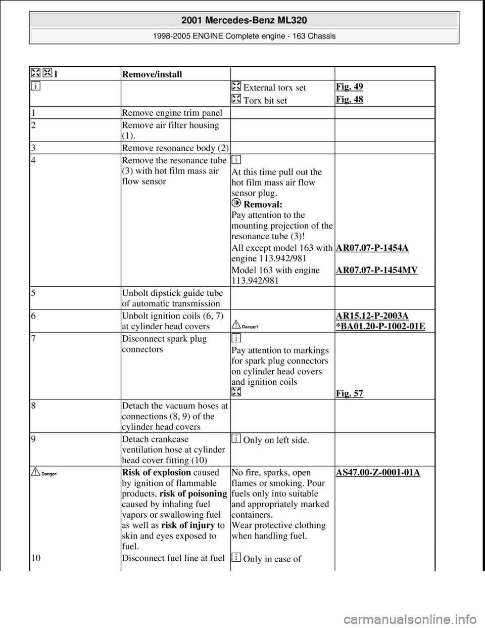
7Disconnect spark plug
connectors
Pay attention to markings
for spark plug connectors
on cylinder head covers
and ignition coils
Fig. 57
8Detach the vacuum hoses at
connections (8, 9) of the
cylinder head covers
9Detach crankcase
ventilation hose at cylinder
head cover fitting (10) Only on left side.
Risk of explosion caused
by ignition of flammable
products, risk of poisoning
caused by inhaling fuel
vapors or swallowing fuel
as well as risk of injury to
skin and eyes exposed to
fuel.No fire, sparks, open
flames or smoking. Pour
fuels only into suitable
and appropriately marked
containers.
Wear protective clothing
when handling fuel.AS47.00-Z-0001-01A
10Disconnect fuel line at fuel Only in case of
2001 Mercedes-Benz ML320
1998-2005 ENGINE Complete engine - 163 Chassis
me
Saturday, October 02, 2010 3:17:56 PMPage 63 © 2006 Mitchell Repair Information Company, LLC.
Page 2444 of 4133
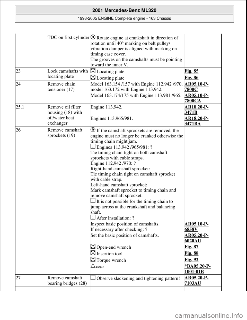
TDC on first cylinder Rotate engine at cra nkshaft in direction of
rotation until 40° marking on belt pulley/
vibration damper is al igned with marking on
timing case cover.
The grooves on the camshafts must be pointing
toward the inner V.
23Lock camshafts with
locating plate Locating plateFig. 85
Locating plateFig. 86
24Remove chain
tensioner (17)Model 163.154 /157 with Engine 112.942 /970,
model 163.172 with Engine 113.942.AR05.10-P-
7800C
Model 163.174/175 with Engine 113.981 /965.AR05.10-P-
7800CA
25.1Remove oil filter
housing (18) with
oil/water heat
exchangerEngine 113.942.AR18.20-P-
3471B
Engines 113.965/981.AR18.20-P-
3471BA
26Remove camshaft
sprockets (19) If the camshaft sprockets are removed, the
engine must no longer be cranked otherwise the
timing chain might jam.
Engines 113.942 /965/981: ?
Tie timing chain tight on both camshaft
sprockets with cable straps.
Engine 112.942 /970: ?
Right-hand camshaft sprocket:
Tie timing chain tight on camshaft sprocket
with cable strap.
Left-hand camshaft sprocket:
Mark camshaft sprocket to timing chain and
remove camshaft sprocket.
It is not possible for the timing chain to
jump across at the crankshaft and balancing
shaft.
After installation: ?
Inspect basic positi on of camshafts.
If necessary after checking: ?AR05.10-P-
6858V
Set the basic position of camshafts.AR05.20-P-
6020AU
Open-end wrenchFig. 87
Insertion toolFig. 88
Torque wrenchFig. 92
*BA05.20-P-
1001-01B
27Remove camshaft
bearing bridges (28) Observe slackening and tightening pattern!AR05.20-P-
7103AU
2001 Mercedes-Benz ML320
1998-2005 ENGINE Complete engine - 163 Chassis
me
Saturday, October 02, 2010 3:17:57 PMPage 88 © 2006 Mitchell Repair Information Company, LLC.