1997 MERCEDES-BENZ ML430 battery
[x] Cancel search: batteryPage 3503 of 4133
AR54.25-P-2800GH
Removing and installing combination switch
21.1.97
MODEL
163.113 /128 /136 /154 /157 /172 /174 /175
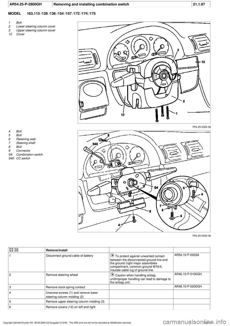
P54.25-0325-06
1
Bolt
2
Lower steering column cover
3
Upper steering column cover
12
Cover
P54.25-0333-06
4
Bolt
5
Bolt
6
Retaining web
7
Steering shaft
8
Bolt
9
Connector
S4
Combination switch
S40
CC switch
Remove/install
1
Disconnect ground cable of battery
To protect against unwanted contact
between the disconnected ground line and
the ground (right major assemblies
compartment, common ground W16/4,
insulate cable lug of ground line.
AR54.10-P-0003A
2
Remove steering wheel
Caution when handling airbag
unitImproper handling can lead to damage to
the airbag unit.
AR46.10-P-0100GH
3
Remove clock spring contact
AR46.10-P-0200GH
4
Unscrew screws (1) and remove lower
steering column molding (2)
5
Remove upper steering column molding (3)
6
Remove covers (12) on left and right
Copyright DaimlerChrysler AG 09.05.2006 CD-Ausgabe G/10/04 . This WIS print-out will not be recorde
d by Modification services.
Page 1
Page 3514 of 4133

Legal regulations on handling and storing
airbags and emergency tensioning retractors
Models 124, 129, 140, 163, 168, 170, 202,
203, 208, 209, 210, 211.004/ 006/ 016/ 061/
065/ 070, 215, 220, 230, 314, 316, 318, 414,
461, 463, 638, 668, 670, 690.6, 901, 902,
903, 904, 905, 950, 952, 953, 954, 970, 972,
974, 975, 976
Model WD141, WD241, WD341, WD641,
WD741, XD141, XD241, XD341, XD441,
XD541, XD641, XD741, YD141, YD241,
YD341, YD441, YD541, YD641, YD741
AH91.00-P-0004-01A
o
Notes on disposing of airbag and emergency
tensioning retractor units
All models
OS91.00-P-0001-01A
1
Disconnect ground cable of battery
To prevent unintended contact, insulate
the ground lead cable lug.
AR54.10-P-0003A
2
Remove instrument panel
AR68.10-P-1000GH
3.1
Open lock (3) on both plugs (4, 5)
As of 01.09.01.
4
Detach plugs (4, 5) from squib
Up to 31.8.01, only one plug (4) is present.
Installation:
Plug/s must audibly latch.
As of 01.09.01: Close lock (3) on plugs after
latching.
5
Slacken self-locking nuts (2) from the front
passenger airbag
*BA91.60-P-1003-01A
6
Remove front passenger airbag
7.1
Render airbag units unusable
Only if airbag unit is replaced.
AR91.60-P-0611A
8
Install in the reverse order
9
Carry out diagnosis
a
Airbag (AB) electrical system test
up to 30.11.99.
AD91.60-P-6000GH
As of 1.12.99: Perform diagnosis with
STAR DIAGNOSIS.
Airbag
Number
Designation
Model
163
BA91.60-P-1003-01A
Nut of front passenger airbag unit to
instrument panel mounting
Nm
8
Copyright DaimlerChrysler AG 09.05.2006 CD-Ausgabe G/10/04 . This WIS print-out will not be recorde
d by Modification services.
Page 2
Page 3520 of 4133
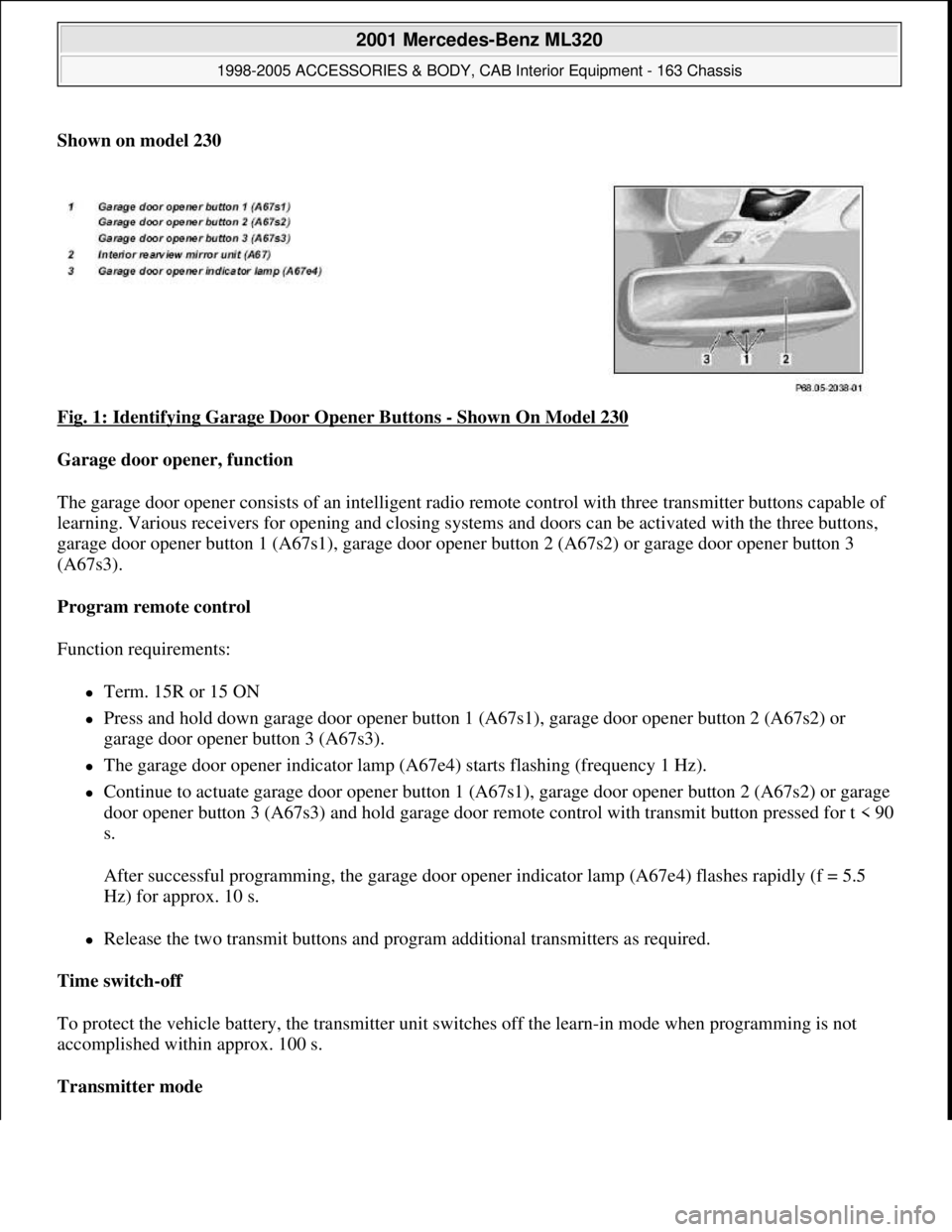
Shown on model 230
Fig. 1: Identifying Garage Door Opener Buttons
- Shown On Model 230
Garage door opener, function
The garage door opener consists of an intelligent radio remote control with three transmitter buttons capable of
learning. Various receivers for opening and closing systems and doors can be activated with the three buttons,
garage door opener button 1 (A67s1), garage door opener button 2 (A67s2) or garage door opener button 3
(A67s3).
Program remote control
Function requirements:
Term. 15R or 15 ON
Press and hold down garage door opener button 1 (A67s1), garage door opener button 2 (A67s2) or
garage door opener button 3 (A67s3).
The garage door opener indicator lamp (A67e4) starts flashing (frequency 1 Hz).
Continue to actuate garage door opener button 1 (A67s1), garage door opener button 2 (A67s2) or garage
door opener button 3 (A67s3) and hold garage door remote control with transmit button pressed for t < 90
s.
After successful programming, the garage door opener indicator lamp (A67e4) flashes rapidly (f = 5.5
Hz) for approx. 10 s.
Release the two transmit buttons and program additional transmitters as required.
Time switch-off
To protect the vehicle battery, the transmitter unit switches off the learn-in mode when programming is not
accomplished within approx. 100 s.
Transmitter mode
2001 Mercedes-Benz ML320
1998-2005 ACCESSORIES & BODY, CAB Interior Equipment - 163 Chassis
me
Saturday, October 02, 2010 3:35:21 PMPage 2 © 2006 Mitchell Repair Information Company, LLC.
Page 3528 of 4133
MODEL 129, 163, 170, 202, 208, 210 as of 1.6.98,215, 220 with CODE (231a) Garage door opener
GARAGE DOOR OPENER DIAGNOSIS, FUNCTION CHECK - AD68.05-P-3000A
MODEL 129, 163, 170, 202, 208, 210 as of 1.6.98,215, 220 with CODE (231a) Garage door opener
GARAGE DOOR OPENER DIAGNOSIS, TROUBLE-SHOOTING - AD68.05-P-5000A
MODELS 129, 163, 170, 202, 208, 210 as of 1.6.98,215, 220 with CODE (231a) Garage door opener
Garage door opener locationModels 129, 202, 208, 210, 215, 220GF68.05-P-1100-01A
Model 170GF68.05-P-1100-01B
Model 163GF68.05-P-1100-01C
Electrical wiring diagramsModel 163PE68.00-P-1100D
Model 170PE68.00-P-1100C
Models 202, 208PE68.00-P-1100B
Model 210PE68.00-P-1100A
Model 220PE68.00-P-1100SA
Model 129, volume 2, FG 68
Connection and use of test equipment AD00.00-P-1000AZ
Diagnostic tools, garage door opener AD68.05-P-2000-01A
Compatibility test for garage door opener AD68.05-P-2000-02A
Garage door opener diagnosis, previous knowledge AD68.05-P-
2000A
Key to diagnostic symbols AD00.00-P-
2001A
Fuses in order
Battery voltage 11-14V
Ignition: ON
Function check
Scope of test Operation / requirement Specified value Possible
cause / remedy
1
Transmitting
push-button
The desired transmitting push-button is programmed.
The vehicle is inside the garage door range.
The garage door opener signal has a range of at least
85% of the range of the garage door hand transmitter or
15m.
Press programmed transmitting push-button.
Garage door is
activated.AD68.05-P-
5000A
Garage door opener
diagnosis, previous
knowledge
AD68.05-P-2000A
2001 Mercedes-Benz ML320
1998-2005 ACCESSORIES & BODY, CAB Interior Equipment - 163 Chassis
me
Saturday, October 02, 2010 3:35:21 PMPage 10 © 2006 Mitchell Repair Information Company, LLC.
Page 3529 of 4133

Fuses in order.
Battery voltage
11-14 V
Ignition: ON
Troubleshooting
Complaint Possible cause Note Remedy
The garage door
cannot be
activated with the
garage door
opener installed
in the vehicle.
The garage door opener
has not been
programmed correctly.
GF68.05-P-0001A
The garage door is
defective
Check garage door: Activate
the garage door with the
hand transmitter. If the
garage door cannot be
opened and closed with the
hand transmitter, the garage
door has a mechanical or
electrical defect.
The garage door's
receiver and the garage
door opener installed in
the vehicle are not
compatible.
A list of compatible garage
doors is included in the
passenger car sales manualIf the used garage door is not
listed check compatibility
with compatibility tester.
Compatibility check of
electrical system for garage
door opener Models 129, 170,
202, 208, 210 as of 1.6.98, 163
as of 1.9.01, 215, 220 with
CODE (231a) garage door
opener Compatibility check for
garage door opener.
AD68.05-P-6000-02A
AD68.05
-P-2000-02A
Voltage supply to
garage door opener
interrupted.Model 208 as of 1.6.98, except
CODE (249a)
Automatic dimming inside
rearview mirror
AD68.05-P-6000-01A
Model 202 as of 1.6.98, Model
210 as of 1.6.98, except CODE
(249a)
Automatic dimming inside
rearview mirror
AD68.05-P-6000-01C
Model 202 as of 1.6.98, Model
208 as of 1.6.98, Model 210 as
of 1.6.98, with CODE (249a) AD68.05-P-6000-01G
2001 Mercedes-Benz ML320
1998-2005 ACCESSORIES & BODY, CAB Interior Equipment - 163 Chassis
me
Saturday, October 02, 2010 3:35:21 PMPage 11 © 2006 Mitchell Repair Information Company, LLC.
Page 3531 of 4133
MODELS 129, 163, 170, 202, 208, 210 as of 1.6.98,215, 220 with CODE (231a) Garage door opener
TESTING & REPAIR
TESTING AND REPAIR WORK: PASSENGER CARS: INTERIOR EQUIPMENT - AR68.00-Z-9163AA
MODEL 163
Garage door opener diagnosis,
previous knowledge AD68.05-P-
2000A
Fuses in order.
Battery voltage 11-14 V
Checking
1Compatibility check of electrical
system for garage door openerModels 129, 170, 202, 208, 210 as of 1.6.98,
163 as of 1.9.01,
215, 220 with CODE (231a) garage door openerAD68.05-P-
6000-02A
2Voltage supply for test of electrical
system for garage door openerModel 208 as of 1.6.98, except CODE (249a)
Automatic dimming inside rearview mirrorAD68.05-P-
6000-01A
3Voltage supply for test of electrical
system for garage door openerModel 129 as of 1.6.98AD68.05-P-
6000-01B
4Voltage supply for test of electrical
system for garage door openerModels 202, 210 as of 1.6.98, except CODE
(249a) Automatic dimming inside rearview
mirrorAD68.05-P-
6000-01C
5Voltage supply for test of electrical
system for garage door openerModel 170 as of 1.6.98AD68.05-P-
6000-01D
6Voltage supply for test of electrical
system for garage door openerModel 163 as of 1.6.98AD68.05-P-
6000-01E
7Voltage supply for test of electrical
system for garage door openerModels 215, 220AD68.05-P-
6000-01F
8Voltage supply for test of electrical
system for garage door openerModels 202, 208, 210 as of 1.6.98, with CODE
(249a) Automatic dimming inside rearview
mirrorAD68.05-P-
6000-01G
Removing and installing
instrument panelMODEL 163.113 /128 /136 /154 /157 /172 /174 /175AR68.10-P-
1000GH
Remove/install center section of
instrument panelMODEL 163.113 /128 /136 /154 /157 /172 /174 /175AR68.10-P-
1030GH
Remove/install bottom section of
instrument panelMODELS 163.113 /128 /136 /154 /157 /172 /174 /175AR68.10-P-
1040GH
Removing and installing side air
nozzleMODELS 163.113 /128 /136 /154 /157 /172 /174 /175AR68.10-P-
1100GH
Remove/install instrument panel
carrierMODEL 163.113 /128 /136 /154 /157 /172 /174 /175AR68.10-P-
1111GH
Removing and installing center AR68.10-P-
2001 Mercedes-Benz ML320
1998-2005 ACCESSORIES & BODY, CAB Interior Equipment - 163 Chassis
me
Saturday, October 02, 2010 3:35:21 PMPage 13 © 2006 Mitchell Repair Information Company, LLC.
Page 3538 of 4133
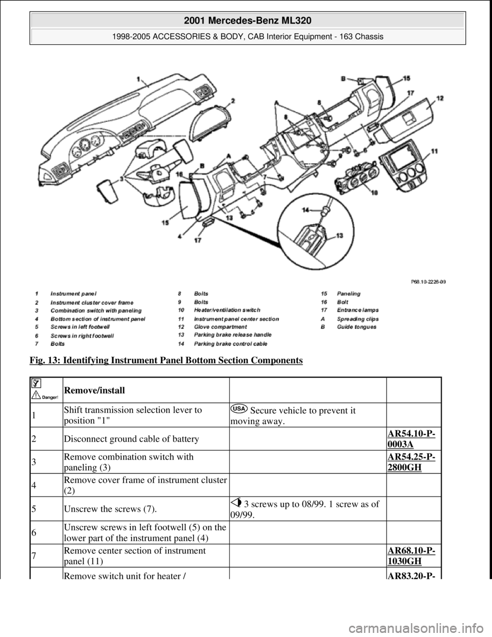
Fig. 13: Identifying Instrument Panel Bottom Section Components
Remove/install
1Shift transmission selection lever to
position "1" Secure vehicle to prevent it
moving away.
2Disconnect ground cable of battery AR54.10-P-
0003A
3Remove combination switch with
paneling (3) AR54.25-P-
2800GH
4Remove cover frame of instrument cluster
(2)
5Unscrew the screws (7). 3 screws up to 08/99. 1 screw as of
09/99.
6Unscrew screws in left footwell (5) on the
lower part of the instrument panel (4)
7Remove center section of instrument
panel (11) AR68.10-P-
1030GH
Remove switch unit for heater / AR83.20-P-
2001 Mercedes-Benz ML320
1998-2005 ACCESSORIES & BODY, CAB Interior Equipment - 163 Chassis
me
Saturday, October 02, 2010 3:35:21 PMPage 20 © 2006 Mitchell Repair Information Company, LLC.
Page 3759 of 4133
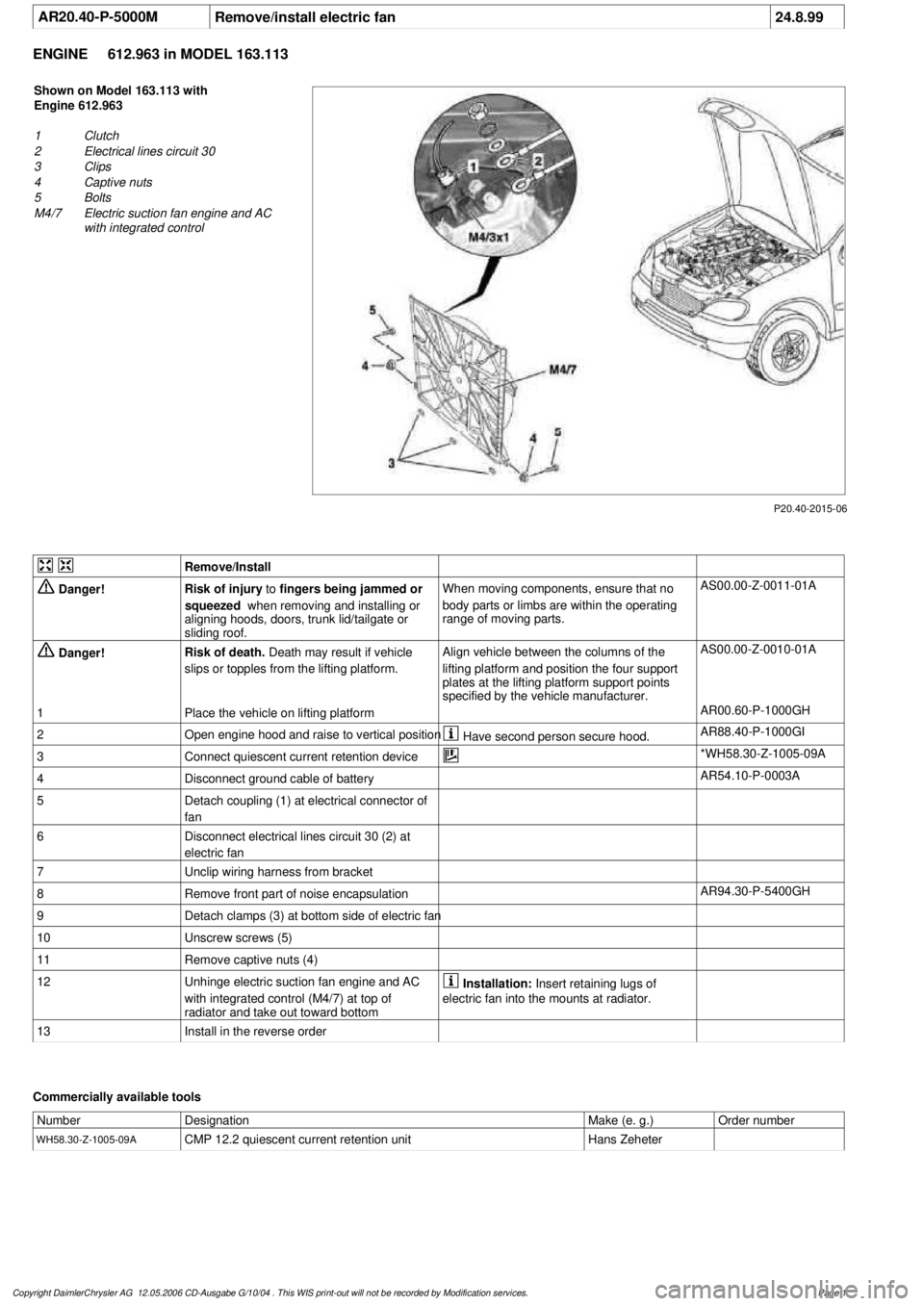
AR20.40-P-5000M
Remove/install electric fan
24.8.99
ENGINE
612.963 in MODEL 163.113
P20.40-2015-06
Shown on Model 163.113 with
Engine 612.963
1
Clutch
2
Electrical lines circuit 30
3
Clips
4
Captive nuts
5
Bolts
M4/7
Electric suction fan engine and AC
with integrated control
Remove/Install
Danger!
Risk of injury
to
fingers being jammed or
squeezed
when removing and installing or
aligning hoods, doors, trunk lid/tailgate or
sliding roof.
When moving components, ensure that no
body parts or limbs are within the operating
range of moving parts.
AS00.00-Z-0011-01A
Danger!
Risk of death.
Death may result if vehicle
slips or topples from the lifting platform.
Align vehicle between the columns of the
lifting platform and position the four support
plates
at the lifting platform support points
specified by the vehicle manufacturer.
AS00.00-Z-0010-01A
1
Place the vehicle on lifting platform
AR00.60-P-1000GH
2
Open engine hood and raise to vertical position
Have second person secure hood.
AR88.40-P-1000GI
3
Connect quiescent current retention device
*WH58.30-Z-1005-09A
4
Disconnect ground cable of battery
AR54.10-P-0003A
5
Detach coupling (1) at electrical connector of
fan
6
Disconnect electrical lines circuit 30 (2) at
electric fan
7
Unclip wiring harness from bracket
8
Remove front part of noise encapsulation
AR94.30-P-5400GH
9
Detach clamps (3) at bottom side of electric fan
10
Unscrew screws (5)
11
Remove captive nuts (4)
12
Unhinge electric suction fan engine and AC
with integrated control (M4/7) at top of
radiator and take out toward bottom
Installation:
Insert retaining lugs of
electric fan into the mounts at radiator.
13
Install in the reverse order
Commercially available tools
Number
Designation
Make (e. g.)
Order number
WH58.30-Z-1005-09A
CMP 12.2 quiescent current retention unit
Hans Zeheter
Copyright DaimlerChrysler AG 12.05.2006 CD-Ausgabe G/10/04 . This WIS print-out will not be recorde
d by Modification services.
Page 1