Page 3441 of 4133

poisoning from swallowing
coolant.Wear protective gloves, protective
clothing and eye protection.
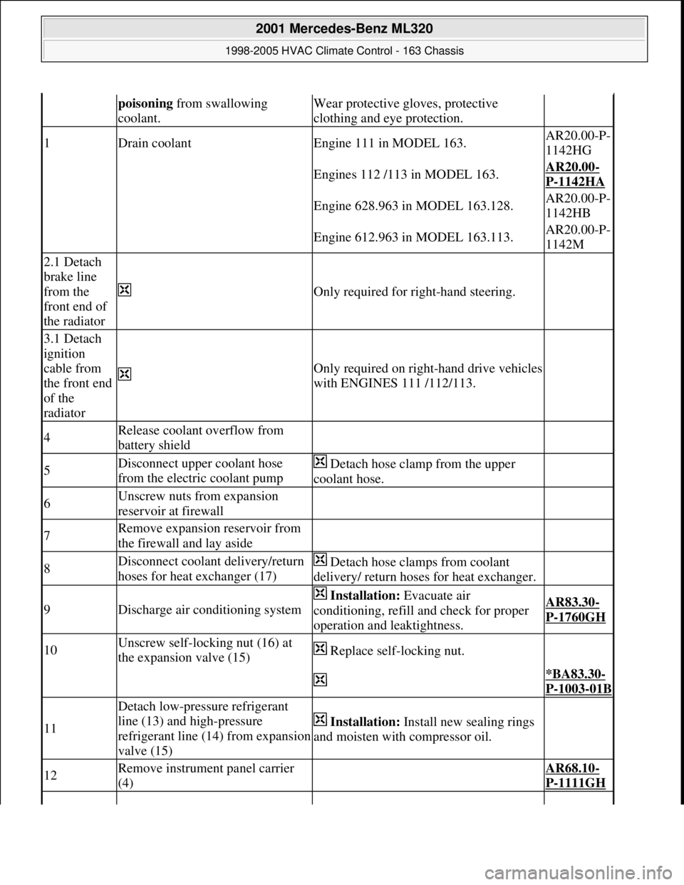
1Drain coolantEngine 111 in MODEL 163.AR20.00-P-
1142HG
Engines 112 /113 in MODEL 163.AR20.00-
P-1142HA
Engine 628.963 in MODEL 163.128.AR20.00-P-
1142HB
Engine 612.963 in MODEL 163.113.AR20.00-P-
1142M
2.1 Detach
brake line
from the
front end of
the radiator
Only required for right-hand steering.
3.1 Detach
ignition
cable from
the front end
of the
radiator
Only required on right-hand drive vehicles
with ENGINES 111 /112/113.
4Release coolant overflow from
battery shield
5Disconnect upper coolant hose
from the electric coolant pump Detach hose clamp from the upper
coolant hose.
6Unscrew nuts from expansion
reservoir at firewall
7Remove expansion reservoir from
the firewall and lay aside
8Disconnect coolant delivery/return
hoses for heat exchanger (17) Detach hose clamps from coolant
delivery/ return hoses for heat exchanger.
9Discharge air conditioning system
Installation: Evacuate air
conditioning, refill and check for proper
operation and leaktightness.AR83.30-
P-1760GH
10Unscrew self-locking nut (16) at
the expansion valve (15) Replace self-locking nut.
*BA83.30-
P-1003-01B
11
Detach low-pressure refrigerant
line (13) and high-pressure
refrigerant line (14) from expansion
valve (15)
Installation: Install new sealing rings
and moisten with compressor oil.
12Remove instrument panel carrier
(4) AR68.10-
P-1111GH
2001 Mercedes-Benz ML320
1998-2005 HVAC Climate Control - 163 Chassis
me
Saturday, October 02, 2010 3:23:18 PMPage 197 © 2006 Mitchell Repair Information Company, LLC.
Page 3461 of 4133
Fig. 174: Identifying Air Conditioning Control Module Components
REMOVE AND INSTALL EVAPORATOR TEMPERATURE SENSOR - AR83.30-P-8085GH
MODEL 163 with CODE (580) Air conditioning or Tempmatic for USA
Fig. 175: Identifying Evaporator Temperature Sensor Components
Removal, installation
1Disconnect ground cable of battery AR54.10-P-0003A
2Remove switch unit for heater/ ventilation (1) AR83.20-P-
1835GH
3Unscrew bolt (4) for air conditioning control module (N19) at
evaporator housing (3)
4Disconnect connector (5) at air conditioning control module (N19)
5Detach air conditioning control module (N19) from evaporator
housing (3)
6Install in the reverse order
7Encode radio AR82.60-P-7502-
01GH
8Read out diagnostic trouble code memory, erase and set clock
2001 Mercedes-Benz ML320
1998-2005 HVAC Climate Control - 163 Chassis
me
Saturday, October 02, 2010 3:23:19 PMPage 217 © 2006 Mitchell Repair Information Company, LLC.
Page 3475 of 4133
REMOVAL & INSTALLATION
INSTALL AUXILIARY WIRING HARNESS - SM83.30-P-0009GH
MODEL 163.154 #A up to 289564, 163.154 #X, 163.136 /172 with CODE (580) Air conditioning (or
Tempmatic for USA)
Fig. 188: Identifying Auxiliary Wiring Harness Location
Operation no. of operation texts or standard texts and flat rates
CategoryOp.
no.Operation textTimeAcc.
no.Code
P023731INSTALLING MODIFIED WIRING HARNESS FOR
Additional fan (AFTER CHECKING)015WU/1.3h--
Removing
1Disconnect battery ground
cable AR54.10-P-
0003A
*BA54.10-
P-1017-01C
2Remove rear cover from
fuse and relay module (F1) 5 screws.
3
Remove mounting screws of
fuse holder on fuse and relay
module (F1) and lay down to
2001 Mercedes-Benz ML320
1998-2005 HVAC Climate Control - 163 Chassis
me
Saturday, October 02, 2010 3:23:19 PMPage 231 © 2006 Mitchell Repair Information Company, LLC.
Page 3477 of 4133
Battery
Parts ordering notes
14
(2) into plug location 1 of
connector (ML/B) and close
connector housing.in connector.
15
Insert blue connector
(ML/B) at bottom of fuse
holder and fasten auxiliary
wiring harness (2) to
separated lead with adhesive
tape
Ensure that stripped wire ends are insulated with
adhesive tape.
16
Fasten fuse holder to fuse
and relay module with
screws
17Insert new 40 A fuse at
position f44 in fuse holder The larger line diameter of the auxiliary wiring
harness (2) allows installation of a 40 A fuse.
18Install in the reverse order
19Check function of additional
fan
NumberDesignationModel 163
BA54.10-P-1017-01CNut, ground cable to bodyNm18
Part no.DesignationQuantity
163 540 00 35Auxiliary wiring harness1
910153 000000Fuse, 40 A1
2001 Mercedes-Benz ML320
1998-2005 HVAC Climate Control - 163 Chassis
me
Saturday, October 02, 2010 3:23:19 PMPage 233 © 2006 Mitchell Repair Information Company, LLC.
Page 3485 of 4133

Rims
D
When changing wheels, for instance, when replacing steel
wheels with light-alloy rims, ensure that the wheel bolts
required for the spare wheel are stored in a clearly visible
location.
D
Since December 1994 models 202 and 124 with special
equipment light alloy disk wheels, are supplied with a sheet
steel spare wheel instead of a light alloy spare wheel. The
necessary wheel bolts are included with the steel spare wheel.
D
Only use approved Mercedes-Benz rims of the same version.
D
Reinforced steel rims are identified by a sticker on the wheel
disc.
D
The wheel bolts on steel and light-alloy rims should always be
tightened to the specified tightening torque using a torque
wrench.
It is not necessary to retorque the lug bolts after approximately
100 to 500 km.
D
The seat for the tire bead must display no corrosion marks.
D
Before inserting a new rubber valve, clean the contact surfaces
on the disk wheel.
On sheet steel-disk wheel wheel trims must be fitted to support
the rubber valve.
Damaged or deformed rims must not be repaired.
Tire pressure monitor
D
Before replacing a tire, check the date of manufacturer of the
wheel sensor: wheel sensors which are more than 5 years old
must be replaced.
D
Use STAR DIAGNOSIS to read out the actual values of the tire
pressure monitor. Check the remaining life of the wheel sensor
battery, replace the wheel sensor if necessary.
Copyright DaimlerChrysler AG 06.07.2006 CD-Ausgabe G/10/04 . This WIS print-out will not be recorde
d by Modification services.
Page 2
Page 3489 of 4133

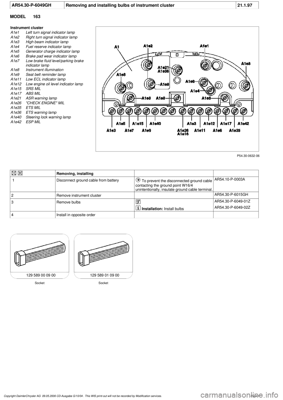
AR54.30-P-6049GH
Removing and installing bulbs of instrument cluster
21.1.97
MODEL
163
P54.30-0632-06
Instrument cluster
A1e1
Left turn signal indicator lamp
A1e2
Right turn signal indicator lamp
A1e3
High beam indicator lamp
A1e4
Fuel reserve indicator lamp
A1e5
Generator charge indicator lamp
A1e6
Brake pad wear indicator lamp
A1e7
Low brake fluid level/parking brake
indicator lamp
A1e8
Instrument illumination
A1e9
Seat belt reminder lamp
A1e11
Low ECL indicator lamp
A1e12
Low engine oil level indicator lamp
A1e15
SRS MIL
A1e17
ABS MIL
A1e21
ASR warning lamp
A1e26
"CHECK ENGINE" MIL
A1e35
ETS MIL
A1e36
ETS warning lamp
A1e40
Steering lock warning lamp
A1e42
ESP MIL
Removing, installing
1
Disconnect ground cable from battery
To prevent the disconnected ground cable
contacting the ground point W16/4
unintentionally, insulate ground cable terminal.
AR54.10-P-0003A
2
Remove instrument cluster
AR54.30-P-6015GH
3
Remove bulbs
AR54.30-P-6049-01Z
Installation:
Install bulbs
AR54.30-P-6049-02Z
4
Install in opposite order
129 589 00 09 00 129 589 01 09 00
Socket
Socket
Copyright DaimlerChrysler AG 09.05.2006 CD-Ausgabe G/10/04 . This WIS print-out will not be recorde
d by Modification services.
Page 1
Page 3493 of 4133
AR54.30-P-6015GH
Remove instrument cluster
20.1.97
MODEL
163.113 /128 /136 /154 /157 /172 /174 /175
P54.25-2680-06
Steering wheel removed for clarity
3
Upper steering column cover
12
Side covering
P54.30-0630-06
Steering wheel removed for clarity
4
Clips
5
Frames
6
Hook
7
Lug
8
Mount
9
Screw
10
Spreading clips
11
Connector
13
Mount
A1
Instrument cluster
Remove, Install
1
Disconnect ground cable of battery
To prevent unintended contact, insulate
the ground lead cable lug.
AR54.10-P-0003A
2
Unlock steering wheel and move to its lowest
position
See Operating Instructions
3
Remove upper steering column cover (3)
Risk of fracturing! Do not scratch the
steering wheel.
Only as of VIN A145273, X708319:
Loosen clips on the side and front. Gently
squeeze the cover together and pull out
between the steering wheel and instrument
panel.
Copyright DaimlerChrysler AG 09.05.2006 CD-Ausgabe G/10/04 . This WIS print-out will not be recorde
d by Modification services.
Page 1
Page 3499 of 4133

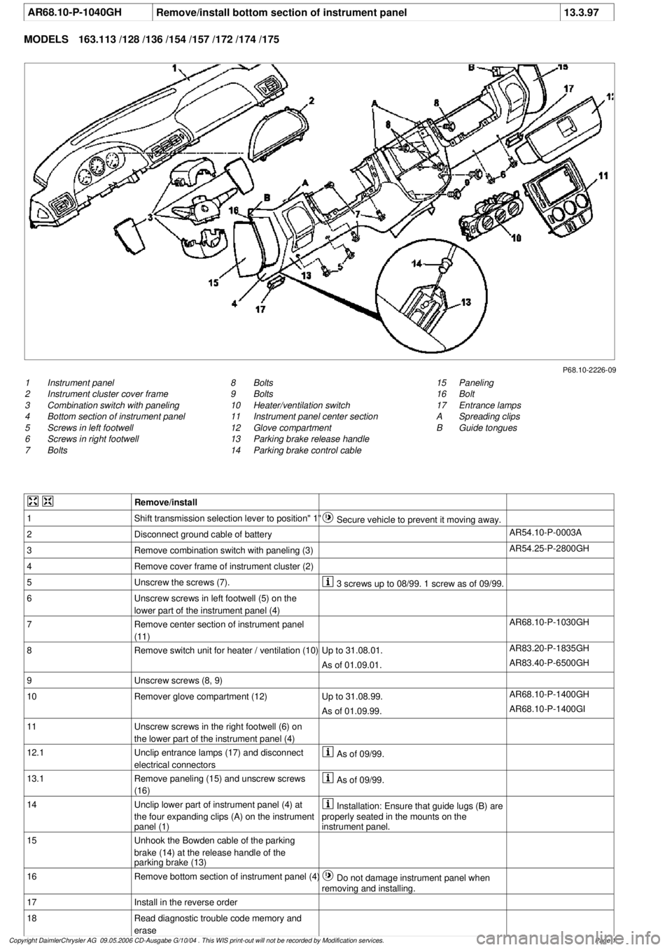
AR68.10-P-1040GH
Remove/install bottom section of instrument panel
13.3.97
MODELS
163.113 /128 /136 /154 /157 /172 /174 /175
P68.10-2226-09
1
Instrument panel
2
Instrument cluster cover frame
3
Combination switch with paneling
4
Bottom section of instrument panel
5
Screws in left footwell
6
Screws in right footwell
7
Bolts
15
Paneling
16
Bolt
17
Entrance lamps
A
Spreading clips
B
Guide tongues
8
Bolts
9
Bolts
10
Heater/ventilation switch
11
Instrument panel center section
12
Glove compartment
13
Parking brake release handle
14
Parking brake control cable
Remove/install
1
Shift transmission selection lever to position" 1"
Secure vehicle to prevent it moving away.
2
Disconnect ground cable of battery
AR54.10-P-0003A
3
Remove combination switch with paneling (3)
AR54.25-P-2800GH
4
Remove cover frame of instrument cluster (2)
5
Unscrew the screws (7).
3 screws up to 08/99. 1 screw as of 09/99.
6
Unscrew screws in left footwell (5) on the
lower part of the instrument panel (4)
7
Remove center section of instrument panel
(11)
AR68.10-P-1030GH
8
Remove switch unit for heater / ventilation (10)
Up to 31.08.01.
AR83.20-P-1835GH
As of 01.09.01.
AR83.40-P-6500GH
9
Unscrew screws (8, 9)
10
Remover glove compartment (12)
Up to 31.08.99.
AR68.10-P-1400GH
As of 01.09.99.
AR68.10-P-1400GI
11
Unscrew screws in the right footwell (6) on
the lower part of the instrument panel (4)
12.1
Unclip entrance lamps (17) and disconnect
electrical connectors
As of 09/99.
13.1
Remove paneling (15) and unscrew screws
(16)
As of 09/99.
14
Unclip lower part of instrument panel (4) at
the four expanding clips (A) on the instrument
panel (1)
Installation: Ensure that guide lugs (B) are
properly seated in the mounts on the
instrument panel.
15
Unhook the Bowden cable of the parking
brake (14) at the release handle of the
parking brake (13)
16
Remove bottom section of instrument panel (4)
Do not damage instrument panel when
removing and installing.
17
Install in the reverse order
18
Read diagnostic trouble code memory and
erase
Copyright DaimlerChrysler AG 09.05.2006 CD-Ausgabe G/10/04 . This WIS print-out will not be recorde
d by Modification services.
Page 1