Page 1265 of 1503
Ignition System
Ignition Coils/Spark Plugs Removal
CAUTION:
Ignition coils and spark plugs can become very hot in
use; do not touch them until the engine has cooled
down.
1. Remove the ignition coil covers.
2. Disconnect the 3P connectors from the ignition
coils.
3. Remove the ignition coils.
4. Remove the spark plugs.
NOTE: Different ignition coils and ignition coil
covers are used for the front and rear cylinders. Be
sure to use the correct ones when mounting them.
IGNITION COIL COVER
RUBBER
SEAL
PLATINUM TIP SPARK PLUG
CYLINDER HEAD
COVER
3P CONNECTOR
IGNITION COILProCarManuals.com
Page 1284 of 1503
Radiator and Condenser Fan Controls
Control Unit Terminals
THROTTLE VALVE CONTROL
MOTOR RELAY
Wire
Terminal Color
Connects to
1
2
3
4
5
6
7
8
9
10
11
12
-
LT GRN
GRY/BLK
BLU/RED
BLK
BRN/BLK
GRN
—
ORN/BLU
BLU/BLK
YEL/BLK
GRN/BLK
Not used
Radiator fan control sensor
Climate control unit
Radiator fan high and engine
compartment fan relays coil
Ground (G401, G402, G403)
A/C triple pressure switch A
Radiator fan control sensor
Not used
Condenser fan relay coil
ECM
(ACS)
IG2 (Power supply)
Radiator fan low relay coil
1. Disconnect the 3P connector from the resistor.
3P CONNECTOR
RADIATOR
FAN
RESISTOR
NOT USED
2. Using an ohmmeter, measure resistance between
the A and B terminals. Replace the resistor if the
resistance is not within specifications.
NOTE: Resistance will vary with the resistor
temperature; specifications are at 68°F (20°C).
Radiator Fan Resistor
Resistance: 0.54—0.66 ohms
Radiator Fan Resistor TestProCarManuals.com
Page 1299 of 1503

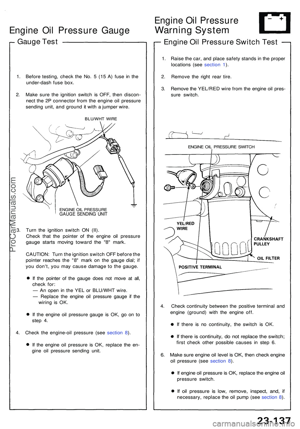
Engine Oi l Pressur e Gaug e
Gauge Tes t
1. Befor e testing , chec k th e No . 5 (15 A ) fus e i n th e
under-das h fus e box .
2 . Mak e sur e th e ignitio n switc h i s OFF , the n discon -
nec t th e 2 P connecto r fro m th e engin e oi l pressur e
sendin g unit , an d groun d i t wit h a jumpe r wire .
BLU/WH T WIR E
ENGIN E OI L PRESSUR E
GAUGE SENDIN G UNI T
3. Tur n th e ignitio n switc h O N (II) .
Chec k tha t th e pointe r o f th e engin e oi l pressur e
gauge start s movin g towar d th e "8 " mark .
CAUTION : Tur n th e ignitio n switc h OF F befor e th e
pointe r reache s th e "8 " mar k o n th e gaug e dial ; i f
yo u don't , yo u ma y cause damag e t o th e gauge .
I f th e pointe r o f th e gaug e doe s no t mov e a t all ,
chec k for :
— A n ope n i n th e YE L o r BLU/WH T wire .
— Replac e th e engin e oi l pressur e gaug e i f th e
wirin g i s OK .
I f th e engin e oi l pressur e gaug e i s OK , g o o n t o
ste p 4 .
4 . Chec k th e engine-oi l pressur e (se e sectio n 8 ).
I f th e engin e oi l pressur e i s OK , replac e th e en -
gin e oi l pressur e sendin g unit .
Engin e Oi l Pressur e
Warning Syste m
Engine Oi l Pressur e Switc h Tes t
1. Rais e th e car , an d plac e safet y stand s i n th e prope r
location s (se e sectio n 1 ).
2 . Remov e th e righ t rea r tire .
3 . Remov e th e YEL/RE D wir e fro m th e engin e oi l pres -
sur e switch .
ENGINE OI L PRESSUR E SWITC H
4. Chec k continuit y betwee n th e positiv e termina l an d
engin e (ground ) wit h th e engin e off .
I f ther e i s n o continuity , th e switc h i s OK .
If ther e is continuity , d o no t replac e th e switch ;
first chec k othe r possible causes i n ste p 6 .
6. Mak e sur e engin e oi l leve l i s OK , the n chec k engin e
oil pressur e (se e sectio n 8 ).
If engin e oi l pressur e is OK , replac e th e engin e oi l
pressur e switch .
If oi l pressur e i s low , remove , inspect , and , i f
necessary , replac e th e oi l pum p (se e sectio n 8 ).
ProCarManuals.com
Page 1323 of 1503

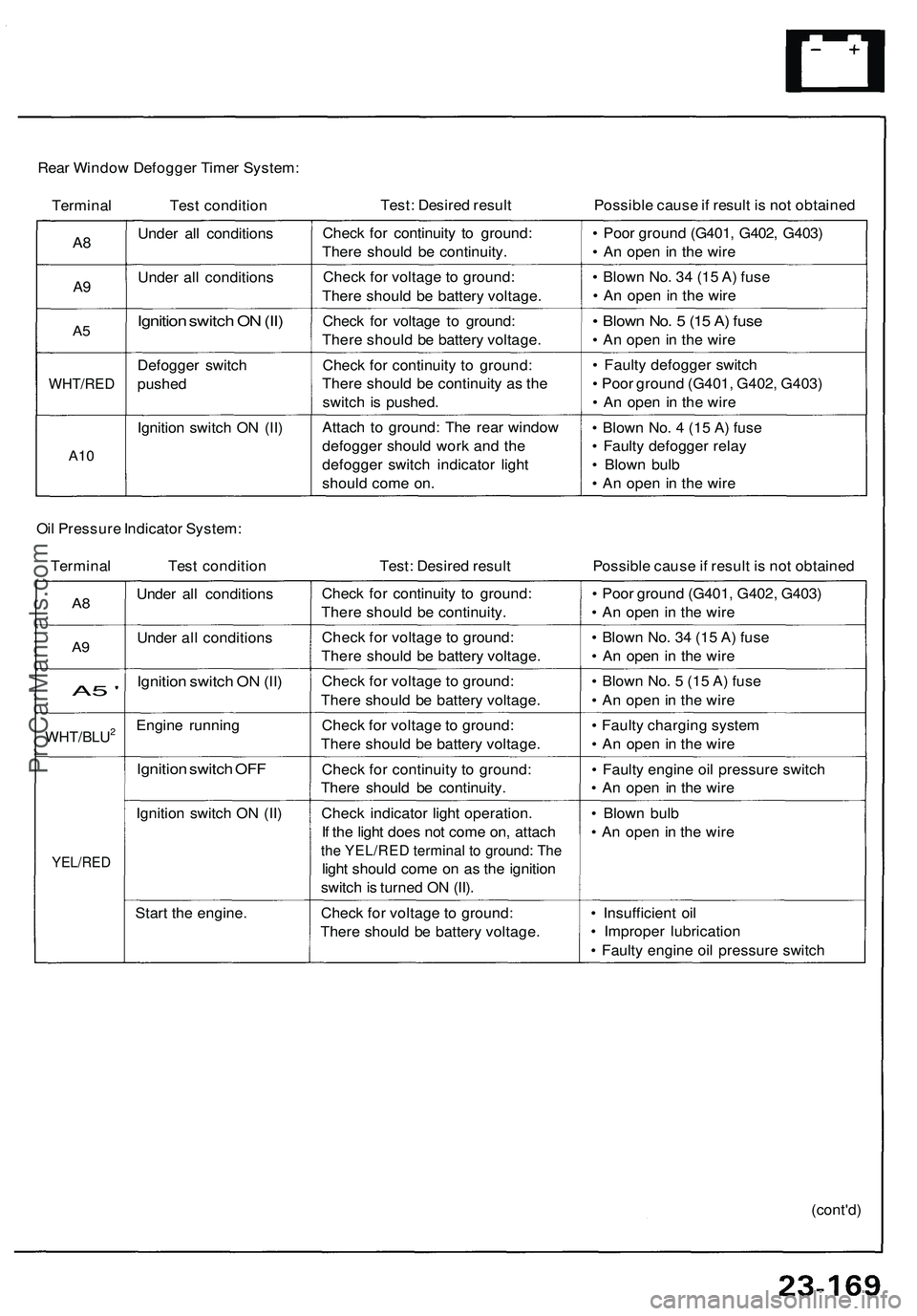
Rear Window Defogger Timer System:
Terminal Test condition
Test: Desired result
Possible cause if result is not obtained
A8
A9
A5
WHT/RED
A10
Under all conditions
Under all conditions
Ignition switch ON (II)
Defogger switch
pushed
Ignition switch ON (II)
Check for continuity to ground:
There should be continuity.
Check for voltage to ground:
There should be battery voltage.
Check for voltage to ground:
There should be battery voltage.
Check for continuity to ground:
There should be continuity as the
switch is pushed.
Attach to ground: The rear window
defogger should work and the
defogger switch indicator light
should come on.
• Poor ground (G401, G402, G403)
• An open in the wire
• Blown No. 34 (15 A) fuse
• An open in the wire
• Blown No. 5 (15 A) fuse
• An open in the wire
• Faulty defogger switch
• Poor ground (G401, G402, G403)
• An open in the wire
• Blown No. 4 (15 A) fuse
• Faulty defogger relay
• Blown bulb
• An open in the wire
Oil Pressure Indicator System:
Terminal Test condition
Test: Desired result
Possible cause if result is not obtained
A8
A9
A5 '
WHT/BLU2
YEL/RED
Under all conditions
Under all conditions
Ignition switch ON (II)
Engine running
Ignition switch OFF
Ignition switch ON (II)
Start the engine.
Check for continuity to ground:
There should be continuity.
Check for voltage to ground:
There should be battery voltage.
Check for voltage to ground:
There should be battery voltage.
Check for voltage to ground:
There should be battery voltage.
Check for continuity to ground:
There should be continuity.
Check indicator light operation.
If the light does not come on, attach
the YEL/RED terminal to ground: The
light should come on as the ignition
switch is turned ON (II).
Check for voltage to ground:
There should be battery voltage.
• Poor ground (G401, G402, G403)
• An open in the wire
• Blown No. 34 (15 A) fuse
• An open in the wire
• Blown No. 5 (15 A) fuse
• An open in the wire
• Faulty charging system
• An open in the wire
• Faulty engine oil pressure switch
• An open in the wire
• Blown bulb
• An open in the wire
• Insufficient oil
• Improper lubrication
• Faulty engine oil pressure switch
(cont'd)ProCarManuals.com