Page 495 of 1503
Crankshaft
Installation
Before installing the crankshaft, apply a coat of
engine oil to the main bearings and rod bear-
ings.
1. Insert bearing halves in the engine block and con-
necting rods.
2. Lower the crankshaft into the block.
THRUST WASHERS
Grooved sides face outward.
3. Install the thrust washers on the No. 3 journal. Oil
thrust washer surfaces.
4. Install the bearings and caps. Tighten 9 x 1.25 mm
cap bolts to the specified torque.
Torque: 39 N-m (4.0 kgf-m, 29 Ibf-ft)
TIMING BELT
PULLEY SIDE
JOURNAL NUMBERS
NOTE:
• Guide the piston carefully to prevent damage.
• Fit long rubber hoses (about 30 cm long) to con-
necting rod bolts to protect the crankshaft.
• Install the pistons after setting the crankshaft to
BDC for each cylinder.
CORRECT
INCORRECT
RUBBER HOSES
8 x
0.75
mm
20 N-m (2.0 kgf-m, 14 Ibf-ft)
after turn to 116°
MARK
• Line up the marks when installing connecting
rod
cap.
BEARING CAP
WASHERS
BEARING CAPSProCarManuals.com
Page 496 of 1503

Crankshaft
Installation (cont'd )
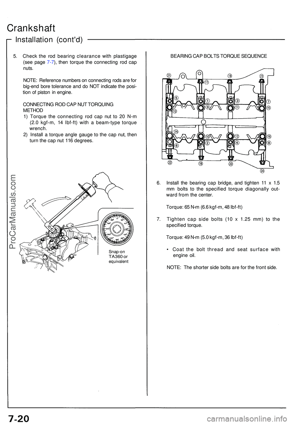
5. Chec k th e ro d bearin g clearanc e wit h plastigag e
(se e pag e 7-7 ), the n torqu e th e connectin g ro d ca p
nuts .
NOTE : Referenc e number s o n connectin g rod s ar e fo r
big-en d bor e toleranc e an d d o NO T indicat e th e posi -
tio n o f pisto n i n engine .
CONNECTIN G RO D CA P NU T TORQUIN G
METHO D
1 ) Torqu e th e connectin g ro d ca p nu t t o 2 0 N- m
(2. 0 kgf-m , 1 4 Ibf-ft ) wit h a beam-typ e torqu e
wrench .
2 ) Instal l a torqu e angl e gaug e t o th e ca p nut , the n
tur n th e ca p nu t 11 6 degrees .
Snap-onTA360 o requivalen t
BEARING CAP BOLTS TORQUE SEQUENCE
6 . Instal l th e bearin g ca p bridge , an d tighte n 1 1 x 1. 5
m m bolt s t o th e specifie d torqu e diagonall y out -
war d fro m th e center .
Torque : 6 5 N- m (6. 6 kgf-m , 4 8 Ibf-ft )
7 . Tighte n ca p sid e bolt s (1 0 x 1.2 5 mm ) t o th e
specifie d torque .
Torque : 4 9 N- m (5. 0 kgf-m , 3 6 Ibf-ft )
• Coa t th e bol t threa d an d sea t surfac e wit h
engin e oil .
NOTE : Th e shorte r sid e bolt s ar e fo r th e fron t side .
ProCarManuals.com
Page 497 of 1503

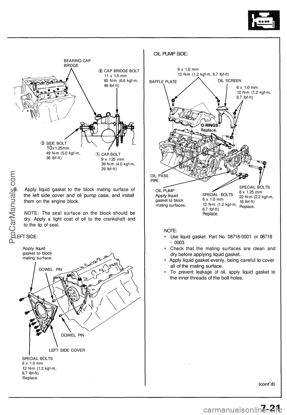
BEARING CA P
BRIDG E
CAP BRIDG E BOL T
11 x 1. 5 m m65 N- m (6. 6 kgf-m ,
4 8 Ibf-ft )
SID E BOL T
10 x 1.2 5 m m49 N- m (5. 0 kgf-m ,
3 6 Ibf-ft ) CA
P BOL T
9 x 1.2 5 mm39 N- m (4. 0 kgf-m ,
2 9 Ibf-ft )
8. Appl y liqui d gaske t t o th e bloc k matin g surfac e o f
the lef t sid e cove r an d oi l pum p case , an d instal l
them o n th e engine block.
NOTE : Th e sea l surfac e o n th e bloc k shoul d b e
dry . Appl y a ligh t coa t o f oi l t o th e crankshaf t an d
t o th e li p o f seal .
LEF T SIDE :
Apply liqui dgaske t t o bloc kmatin g surface .
LEFT SID E COVE R
SPECIA L BOLT S6 x 1. 0 m m12 N- m (1. 2 kgf-m ,8.7 Ibf-ft )Replace .
OIL PUM P SIDE :
6 x 1. 0 m m12 N- m (1. 2 kgf-m , 8. 7 Ibf-ft )
BAFFL E PLAT E OI
L SCREE N
6 x 1. 0 m m12 N- m (1. 2 kgf-m ,
8. 7 Ibf-ft )
OI L PAS S
PIPE
OIL PUM PApply liqui dgaske t t o bloc k
matin g surfaces .
NOTE:
SPECIA L BOLT S6 x 1. 0 m m12 N- m (1. 2 kgf-m ,
8. 7 Ibf-ft )
Replace .
SPECIAL BOLT S8 x 1.2 5 mm22 N- m (2. 2 kgf-m ,16 Ibf-ft )
Replace .
• Us e liqui d gasket . Par t No . 0871 8-000 1 o r 0871 8
- 0003 .
• Chec k tha t th e matin g surface s ar e clea n an d
dry befor e applyin g liqui d gasket .
• Appl y liqui d gaske t evenly , bein g carefu l t o cove r
all o f th e matin g surface .
• T o preven t leakag e o f oil , appl y liqui d gaske t t o
th e inne r thread s o f th e bol t holes .
DOWE L PI N
DOWE L PI N
ProCarManuals.com
Page 500 of 1503
Engine Lubricatio n
Illustrated Index
NOTE:
• Us e ne w O-ring s whe n reassembling .
• Appl y oi l t o O-ring s befor e installation .
• Us e liqui d gasket , Par t No . 0871 8-000 1 o r 0871 8-
0003 .
• I f th e botto m o f th e oi l pa n i s deformed , i t shoul d b e
repaire d o r th e oi l pa n shoul d b e replace d t o retai n
prope r clearanc e betwee n th e scree n an d th e bottom .
OIL CONTRO L ORIFIC ERemove wit h 6 m m
bol t an d clean .
O-RIN GReplace .
OIL FILTE R BAS EIllustrate d Index ,
pag e 8-1 2
OIL FILTE ROne tur n o r22 N- m (2. 2 kgf-m ,16 Ibf-ft )Replacemen t 8- 5
OI L PUM P
Illustrate d index , pag e 8- 7
Inspection , pag e 8 -8
Appl y liqui d gaske t t o
matin g surfac e o f engin e block .
OIL PA N GASKE TReplace.
OIL PA N• D o no t defor m
th e bottom .
• Refe r t o pag e 8-1 0whe n installing .
ProCarManuals.com
Page 501 of 1503
Engine Oil
Inspection
1. Check engine oil with the engine off and the car
parked on level ground.
2. Make certain that the oil level indicated on the
dipstick is between the upper and lower marks.
3. If the level has dropped close to the lower mark,
add oil until it reaches the upper mark.
CAUTION: Insert the dipstick carefully to avoid
bending it.ProCarManuals.com
Page 502 of 1503
Replacement
CAUTION: Remove the drain plug carefully while the en-
gine is hot, the hot oil may cause scalding.
1. Warm up the engine.
2. Drain the engine oil.
3. Reinstall the drain plug with a new washer, and refill
with the recommended oil.
NOTE: Under normal conditions, the oil filter should be
replaced at every other oil change. Under severe condi-
tions, the oil filter should be replaced at each oil change.ProCarManuals.com
Page 504 of 1503
Oil Filte r
Replacemen t
CAUTION: Loose n th e oi l filte r carefull y whil e th e
engin e is hot , the hot oi l ma y cause scalding .
1 . Remov e th e oi l filte r wit h th e specia l too l a s shown .
OIL FILTE R WRENC H07912-611000 1Torque: On e tur n(22 N- m (2. 2 kgf-m , 1 6 Ibf-ft) )
2. Inspec t th e thread s an d rubbe r sea l o n th e ne w filter .
Wip e of f th e sea t o n oi l filte r base , the n appl y a ligh t
coa t o f oi l t o th e rubber seal an d instal l th e filter .
3 . Afte r th e rubbe r sea l i s seate d agains t th e base ,
tighte n th e oi l filte r b y turnin g i t approximatel y on e
turn .
Torque : On e tur n (2 2 N- m (2. 2 kgf-m , 1 6 Ibf-ft) )
4 . Star t th e engine , an d chec k th e filte r fo r oi l leakage .
ProCarManuals.com
Page 505 of 1503
Oil Pressur e
Testing
If th e oi l pressur e warnin g ligh t stay s o n wit h th e engin e
running , chec k th e engin e oi l level . I f th e oi l leve l i s
correct :
1 . Remov e th e engine oil pressur e switch , an d instal l
a n oi l pressur e gauge .
2 . Star t th e engine . Shu t i t of f immediatel y i f th e
gaug e register s n o oi l pressure . Repai r th e proble m
before continuing .
3. Allo w th e engin e t o reac h operatin g temperatur e
(fa n come s o n a t leas t twice) . Th e pressur e shoul d
be:
Engin e Oi l Pressure :
A t Idle : 7 0 kP a (0. 7 kgf/cm2,1 0 psi )
minimu m
A t 3,00 0 rpm : 34 0 kP a (3. 5 kgf/cm
2, 5 0 psi )
minimu m
• I f oi l pressur e i s withi n specifications , replac e th e
oi l pressur e sende r an d recheck .
• I f oi l pressur e i s NO T withi n specifications , inspec t
th e oi l pum p (se e pag e 8-8 ).
ENGIN E OI L PRESSUR ESWITCHMOUNTIN G HOL E
OIL PRESSUR E GAUG EADAPTO R(1/8"-28, BSPT )
ProCarManuals.com