Page 420 of 1503
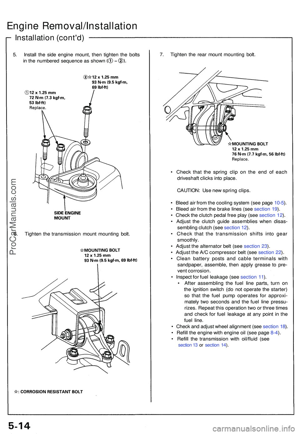
5. Instal l th e sid e engin e mount , the n tighte n th e bolt s
in th e numbere d sequenc e a s show n
Engine Removal/Installatio n
Installation (cont'd )
7. Tighte n th e rea r moun t mountin g bolt .
• Chec k tha t th e sprin g cli p o n th e en d o f eac h
driveshaf t click s int o place .
CAUTION : Us e ne w sprin g clips .
• Blee d ai r fro m th e coolin g syste m (se e pag e 10-5 ).
• Blee d ai r fro m th e brak e line s (se e sectio n 19 ).
• Chec k th e clutc h peda l fre e pla y (se e sectio n 12 ).
• Adjus t th e clutc h guid e assemblie s whe n disas -
semblin g clutc h (se e sectio n 12 ).
• Chec k tha t th e transmissio n shift s int o gea r
smoothly .
• Adjus t th e alternato r bel t (se e sectio n 23 ).
• Adjus t th e A/ C compresso r bel t (se e sectio n 22 ).
• Clea n batter y post s an d cabl e terminal s wit h
sandpaper , assemble , the n appl y greas e t o pre -
ven t corrosion .
• Inspec t fo r fue l leakag e (se e sectio n 11 ).
• Afte r assemblin g th e fue l lin e parts , tur n o n
th e ignitio n switc h (d o no t operat e th e starter )
s o tha t th e fue l pum p operate s fo r approxi -
matel y tw o second s an d th e fue l lin e pressu -
rizes . Repea t thi s operatio n tw o o r thre e time s
an d chec k fo r fue l leakag e a t an y poin t i n th e
fue l line .
• Chec k an d adjus t whee l alignmen t (se e sectio n 18 ).
• Refil l th e engin e wit h engin e oi l (se e pag e 8-4 ).
• Refil l th e transmissio n wit h oil/flui d (se e
section 1 3 o r section 14 ).
6 . Tighte n th e transmissio n moun t mountin g bolt .
ProCarManuals.com
Page 422 of 1503
VTEC
VTEC Solenoid Valve Inspection
1. Disconnect the 2P connector from the VTEC sole-
noid valve.
2. Measure resistance between the BLU/YEL (front/rear)
terminals and body ground.
BLU/YEL
3. If the resistance is within specifications, remove the
VTEC solenoid valve from the cylinder head, and
check the VTEC solenoid valve filter for clogging.
• If there is clogging, replace the engine oil filter
and engine oil.
VTEC SOLENOID VALVE
VTEC SOLENOID VALVE
FILTER/O-RING
Replace.
4. If the filter is not clogged, push the VTEC solenoid
valve with your finger and check its movement.
• If VTEC solenoid valve is normal, check the engine
oil pressure.ProCarManuals.com
Page 438 of 1503
Cylinder Heads
Illustrated Index
CAUTION: To avoid damage, wait until the engine coolant temperature drops below 100°F (38°C) before removing the cylin-
der head.
NOTE: Use new O-rings and gaskets when reassembling.
Prior to reassembling, clean all the parts in solvent, dry them, and apply lubricant to any contact parts.
CAMSHAFT HOLDER
O-RING
Replace.
CAMSHAFT HOLDER
PLATE
CKP/CYP SENSOR
RUBBER SEALS
Replace when damaged
or deteriorated.
BACK COVER
Apply oil to the bolt threads.
FRONT INTAKE
CAMSHAFT
RUBBER SEALS
Replace for oil
leakage.
FRONT EXHAUST
CAMSHAFT
DOWEL PIN
CAMSHAFT PULLEY
(cont'd)ProCarManuals.com
Page 452 of 1503
Camshafts
Inspection
NOTE:
• Do not rotate the camshaft during inspection.
• Remove the rocker arms and rocker shafts.
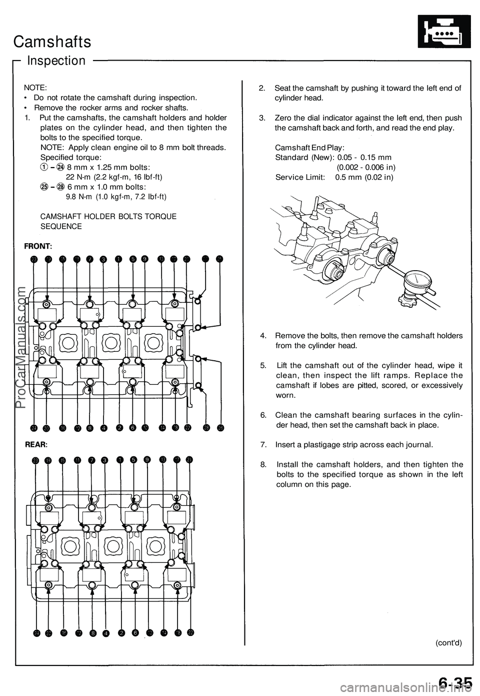
1. Put the camshafts, the camshaft holders and holder
plates on the cylinder head, and then tighten the
bolts to the specified torque.
NOTE: Apply clean engine oil to 8 mm bolt threads.
Specified torque:
8 mm x 1.25 mm bolts:
22 N-m (2.2 kgf-m, 16 Ibf-ft)
6 mm x 1.0 mm bolts:
9.8 N-m (1.0 kgf-m, 7.2 Ibf-ft)
CAMSHAFT HOLDER BOLTS TORQUE
SEQUENCE
2. Seat the camshaft by pushing it toward the left end of
cylinder head.
3. Zero the dial indicator against the left end, then push
the camshaft back and forth, and read the end play.
Camshaft End Play:
Standard (New): 0.05 - 0.15 mm
(0.002 - 0.006 in)
Service Limit: 0.5 mm (0.02 in)
4. Remove the bolts, then remove the camshaft holders
from the cylinder head.
5. Lift the camshaft out of the cylinder head, wipe it
clean, then inspect the lift ramps. Replace the
camshaft if lobes are pitted, scored, or excessively
worn.
6. Clean the camshaft bearing surfaces in the cylin-
der head, then set the camshaft back in place.
7. Insert a plastigage strip across each journal.
8. Install the camshaft holders, and then tighten the
bolts to the specified torque as shown in the left
column on this page.
(cont'd)ProCarManuals.com
Page 467 of 1503
Cylinder Heads
Installation (cont'd)
Rear:
8 x
1.25
mm
22 N-m (2.2 kgf-m,
16 Ibf-ft)
REAR PRIMARY
HEATED OXYGEN SENSOR
(REAR PRIMARY HO2S)
44 N-m (4.5 kgf-m,
33 Ibf-ft)
Be careful not to damage.
GASKET
Replace.
REAR EXHAUST
MANIFOLD
EXHAUST
MANIFOLD
COVER
SELF-LOCKING NUT
8 x
1.25
mm
30 N-m (3.1 kgf-m,
22 Ibf-ft)
Replace.
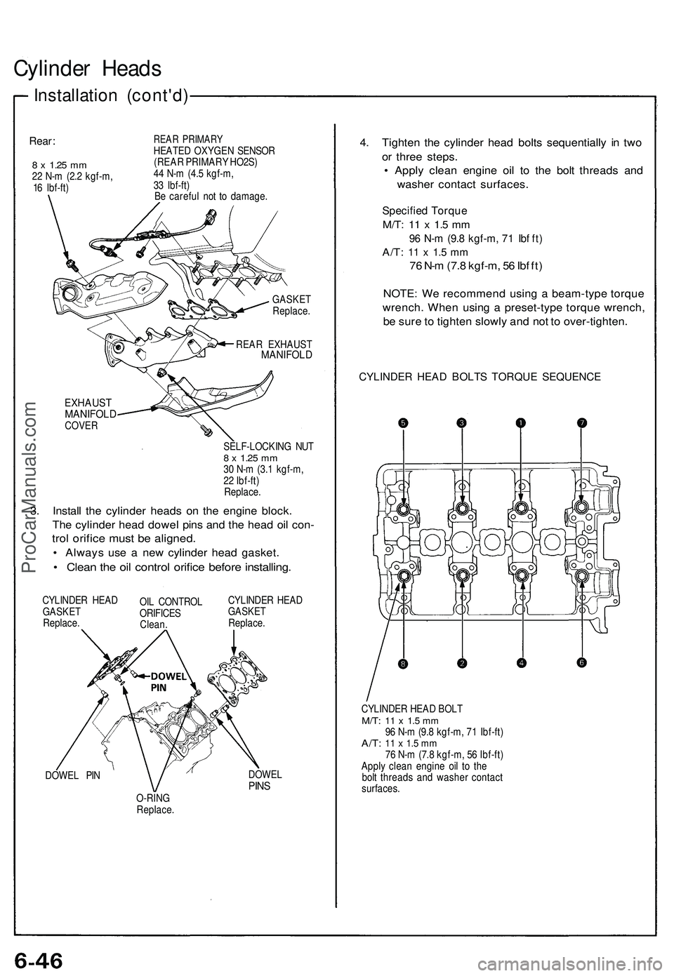
3. Install the cylinder heads on the engine block.
The cylinder head dowel pins and the head oil con-
trol orifice must be aligned.
• Always use a new cylinder head gasket.
• Clean the oil control orifice before installing.
CYLINDER HEAD
GASKET
Replace.
OIL CONTROL
ORIFICES
Clean.
CYLINDER HEAD
GASKET
Replace.
DOWEL PIN
DOWEL
PINS
O-RING
Replace.
4. Tighten the cylinder head bolts sequentially in two
or three steps.
• Apply clean engine oil to the bolt threads and
washer contact surfaces.
Specified Torque
M/T:
11 x 1.5 mm
96 N-m (9.8 kgf-m, 71 Ibf ft)
A/T:
11 x 1.5 mm
76 N-m (7.8 kgf-m, 56 Ibf ft)
NOTE: We recommend using a beam-type torque
wrench. When using a preset-type torque wrench,
be sure to tighten slowly and not to over-tighten.
CYLINDER HEAD BOLTS TORQUE SEQUENCE
CYLINDER HEAD BOLT
M/T:
11 x 1.5 mm
96 N-m (9.8 kgf-m, 71 Ibf-ft)
A/T:
11 x 1.5 mm
76 N-m (7.8 kgf-m, 56 Ibf-ft)
Apply clean engine oil to the
bolt threads and washer contact
surfaces.ProCarManuals.com
Page 470 of 1503
Camshafts
Installation (cont'd)
5. Apply liquid gasket to the head mating surfaces of
the No. 1 and the No. 4 camshaft holders.
5. Apply liquid gasket to the shaded areas.
6. Install the camshaft holders.
NOTE:
• "F" or "R" marks are stamped on the camshaft
holders.
• The arrows must be pointing to the timing belt
side.
• Set two dowel pins in each camshaft holder.
FRONT:
No. 4 No. 3 No. 2 No. 1
CAMSHAFT CAMSHAFT CAMSHAFT CAMSHAFT
HOLDER HOLDER HOLDER HOLDER
No. 4 No. 3 No. 2 No. 1
CAMSHAFT CAMSHAFT CAMSHAFT CAMSHAFT
HOLDER HOLDER HOLDER HOLDER
7. Install the camshaft holder plates.
8. Tighten each bolt two turns at a time in the sequence
shown below to insure that the rockers do not bind
on the valves.
NOTE: Apply clean engine oil to 8 mm bolt threads.
Specified torque:
8 mm x 1.25 mm bolts:
22 N-m (2.2 kgf-m, 16 Ibf-ft)
6 mm x 1.0 mm bolts:
9.8 N-m (1.0 kgf-m, 7.2 Ibf-ft)
CAMSHAFT HOLDER BOLT TORQUE SEQUENCE
FRONT:ProCarManuals.com
Page 472 of 1503
Camshafts
Installation (cont'd)
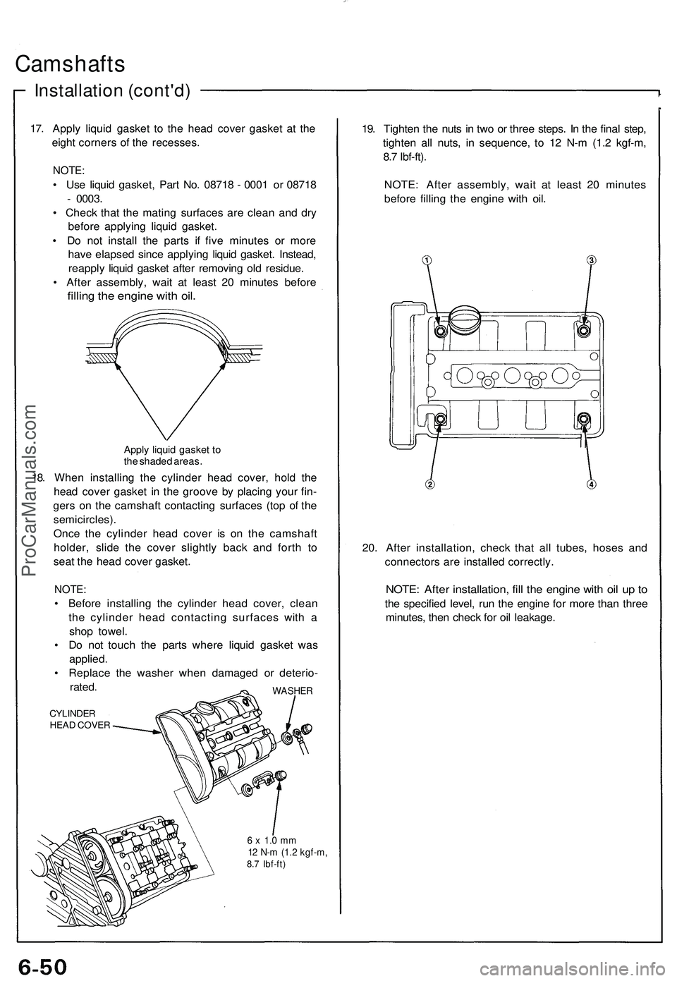
17. Apply liquid gasket to the head cover gasket at the
eight corners of the recesses.
NOTE:
• Use liquid gasket, Part No. 08718 - 0001 or 08718
- 0003.
• Check that the mating surfaces are clean and dry
before applying liquid gasket.
• Do not install the parts if five minutes or more
have elapsed since applying liquid gasket. Instead,
reapply liquid gasket after removing old residue.
• After assembly, wait at least 20 minutes before
filling the engine with oil.
Apply liquid gasket to
the shaded areas.
18. When installing the cylinder head cover, hold the
head cover gasket in the groove by placing your fin-
gers on the camshaft contacting surfaces (top of the
semicircles).
Once the cylinder head cover is on the camshaft
holder, slide the cover slightly back and forth to
seat the head cover gasket.
NOTE:
• Before installing the cylinder head cover, clean
the cylinder head contacting surfaces with a
shop towel.
• Do not touch the parts where liquid gasket was
applied.
• Replace the washer when damaged or deterio-
rated.
CYLINDER
HEAD COVER
WASHER
6 x 1.0 mm
12 N-m (1.2 kgf-m,
8.7 Ibf-ft)
19. Tighten the nuts in two or three steps. In the final step,
tighten all nuts, in sequence, to 12 N-m (1.2 kgf-m,
8.7 Ibf-ft).
NOTE: After assembly, wait at least 20 minutes
before filling the engine with oil.
20. After installation, check that all tubes, hoses and
connectors are installed correctly.
NOTE: After installation, fill the engine with oil up to
the specified level, run the engine for more than three
minutes, then check for oil leakage.ProCarManuals.com
Page 474 of 1503
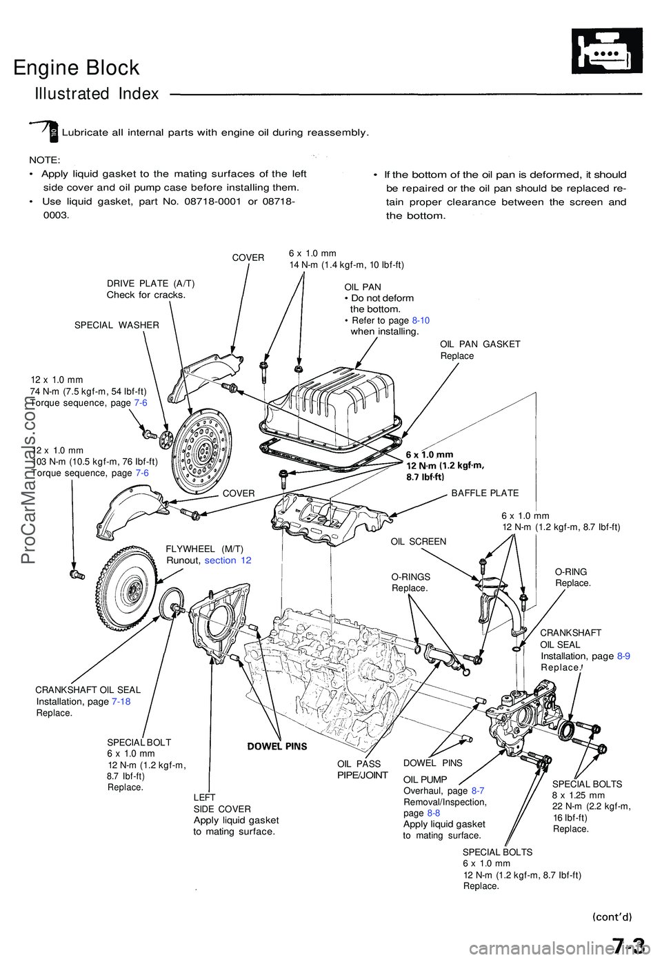
Engine Bloc k
Illustrate d Inde x
Lubricat e al l interna l part s wit h engin e oi l durin g reassembly .
NOTE:
• Appl y liqui d gaske t t o th e matin g surface s o f th e lef t
side cove r an d oi l pum p cas e befor e installin g them .
• Us e liqui d gasket , par t No . 0871 8-000 1 o r 0871 8-
0003 .
• I f th e botto m of th e oi l pa n is deformed , i t shoul d
be repaire d o r th e oi l pa n shoul d b e replace d re -
tain prope r clearanc e betwee n th e scree n an d
the bottom .
COVER
DRIV E PLAT E (A/T )
Check fo r cracks .
SPECIA L WASHER
12 x 1. 0 m m74 N- m (7. 5 kgf-m , 5 4 Ibf-ft )
Torqu e sequence , pag e 7- 6
12 x 1. 0 m m103 N- m (10. 5 kgf-m , 7 6 Ibf-ft )
Torqu e sequence , pag e 7- 6
6 x 1. 0 m m14 N- m (1. 4 kgf-m , 1 0 Ibf-ft )
OIL PA N• D o no t defor mthe bottom .• Refe r t o pag e 8-1 0whe n installing .
OIL PA N GASKE T
Replac e
6 x 1. 0 m m12 N- m (1. 2 kgf-m , 8. 7 Ibf-ft )
O-RIN G
Replace .
CRANKSHAF T
OI L SEA L
Installation , pag e 8- 9Replace .
CRANKSHAF T OI L SEA L
Installation , pag e 7-1 8Replace .
SPECIAL BOL T6 x 1. 0 m m12 N- m (1. 2 kgf-m ,8.7 Ibf-ft )Replace .
OIL PAS SPIPE/JOIN T
LEFTSIDE COVE RApply liqui d gaske tto matin g surface .
DOWEL PIN S
OIL PUM POverhaul , pag e 8- 7
Removal/Inspection ,
pag e 8- 8
Appl y liqui d gaske tto matin g surface . SPECIA
L BOLT S
8 x 1.2 5 mm22 N- m (2. 2 kgf-m ,
1 6 Ibf-ft )
Replace .
SPECIAL BOLT S6 x 1. 0 m m12 N- m (1. 2 kgf-m , 8. 7 Ibf-ft )Replace .
FLYWHEE L (M/T )Runout , sectio n 1 2
COVE R
OIL SCREE N
O-RING S
Replace .BAFFL
E PLAT E
ProCarManuals.com