1997 ACURA NSX engine oil
[x] Cancel search: engine oilPage 507 of 1503
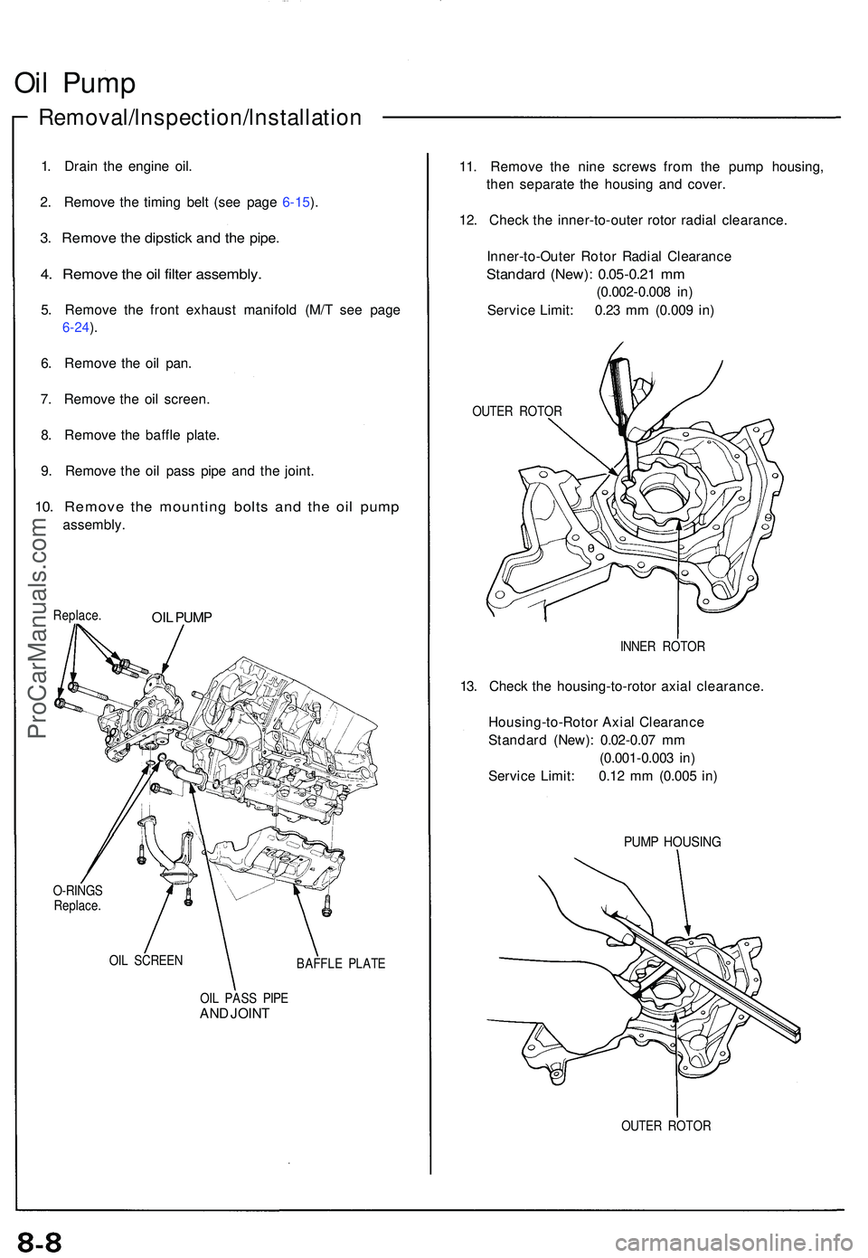
Oil Pum p
Removal/lnspection/lnstallatio n
1. Drai n th e engine oil.
2 . Remov e th e timin g bel t (se e pag e 6-15 ).
3 . Remov e th e dipstic k an d th e pipe .
4. Remov e th e oi l filte r assembly .
5. Remov e th e fron t exhaus t manifol d (M/ T se e pag e
6-24).
6 . Remov e th e oi l pan .
7 . Remov e th e oi l screen .
8 . Remov e th e baffl e plate .
9 . Remov e th e oi l pas s pip e an d th e joint .
10. Remov e th e mountin g bolt s an d th e oi l pum p
assembly . 11
. Remov e th e nin e screw s fro m th e pum p housing ,
the n separat e th e housin g an d cover .
12 . Chec k th e inner-to-oute r roto r radia l clearance .
Inner-to-Oute r Roto r Radia l Clearanc e
Standard (New) : 0.0 5-0.2 1 m m
(0.00 2-0.00 8 in )
Servic e Limit : 0.2 3 m m (0.00 9 in )
Replace .OIL PUM P
O-RING S
Replace .
OI L SCREE N
BAFFLE PLAT E
OI L PAS S PIP E
AND JOIN T
OUTE R ROTO R
13. Chec k th e housing-to-roto r axia l clearance .
Housing-to-Roto r Axia l Clearanc e
Standar d (New) : 0.0 2-0.0 7 m m
(0.00 1-0.00 3 in )
Servic e Limit : 0.1 2 m m (0.00 5 in )
OUTE R ROTO R
PUMP HOUSIN G
INNER ROTO R
ProCarManuals.com
Page 519 of 1503
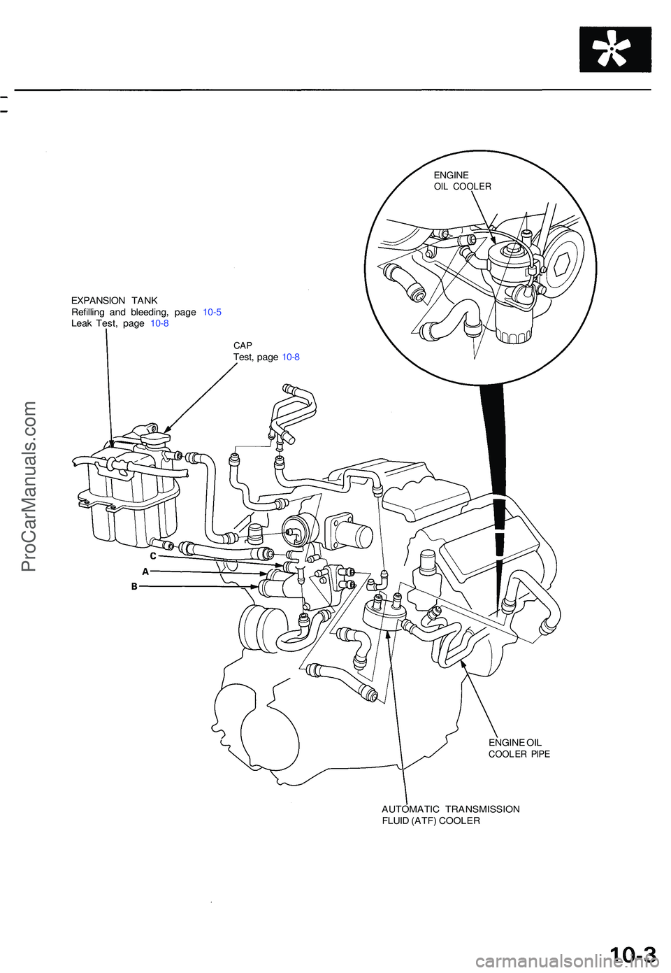
EXPANSION TAN K
Refillin g an d bleeding , pag e 10- 5
Lea k Test , pag e 10- 8
ENGINE OI L
COOLE R PIP E
AUTOMATI C TRANSMISSIO N
FLUI D (ATF ) COOLE R
CAPTest , pag e 10- 8
ENGIN EOIL COOLE R
ProCarManuals.com
Page 572 of 1503
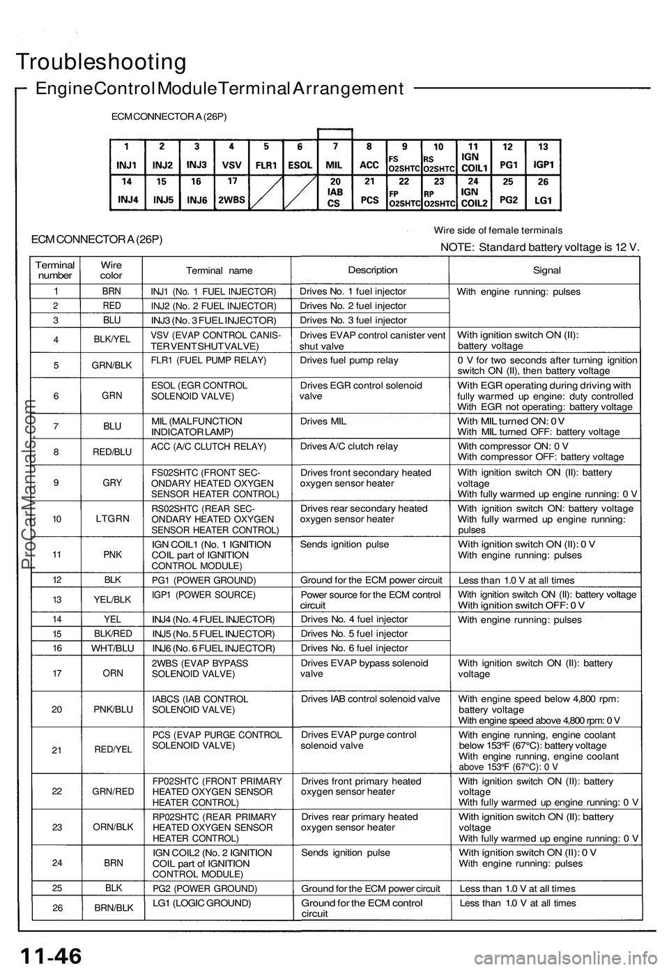
Troubleshooting
Engine Control Module Terminal Arrangement
ECM CONNECTOR A (26P)
ECM CONNECTOR A (26P)
Wire side of female terminals
NOTE: Standard battery voltage is 12 V.
Terminal
number
1
2
3
4
5
6
7
8
9
10
11
12
13
14
15
16
17
20
21
22
23
24
25
26
Wire
color
BRN
RED
BLU
BLK/YEL
GRN/BLK
GRN
BLU
RED/BLU
GRY
LTGRN
PNK
BLK
YEL/BLK
YEL
BLK/RED
WHT/BLU
ORN
PNK/BLU
RED/YEL
GRN/RED
ORN/BLK
BRN
BLK
BRN/BLK
Terminal name
INJ1 (No. 1 FUEL INJECTOR)
INJ2 (No. 2 FUEL INJECTOR)
INJ3 (No. 3 FUEL INJECTOR)
VSV (EVAP CONTROL CANIS-
TER VENT SHUT VALVE)
FLR1 (FUEL PUMP RELAY)
ESOL (EGR CONTROL
SOLENOID VALVE)
MIL (MALFUNCTION
INDICATOR LAMP)
ACC (A/C CLUTCH RELAY)
FS02SHTC (FRONT SEC-
ONDARY HEATED OXYGEN
SENSOR HEATER CONTROL)
RS02SHTC (REAR SEC-
ONDARY HEATED OXYGEN
SENSOR HEATER CONTROL)
IGN COIL1 (No. 1 IGNITION
COIL part of IGNITION
CONTROL MODULE)
PG1 (POWER GROUND)
IGP1 (POWER SOURCE)
INJ4 (No. 4 FUEL INJECTOR)
INJ5 (No. 5 FUEL INJECTOR)
INJ6 (No. 6 FUEL INJECTOR)
2WBS (EVAP BYPASS
SOLENOID VALVE)
IABCS (IAB CONTROL
SOLENOID VALVE)
PCS (EVAP PURGE CONTROL
SOLENOID VALVE)
FP02SHTC (FRONT PRIMARY
HEATED OXYGEN SENSOR
HEATER CONTROL)
RP02SHTC (REAR PRIMARY
HEATED OXYGEN SENSOR
HEATER CONTROL)
IGN COIL2 (No. 2 IGNITION
COIL part of IGNITION
CONTROL MODULE)
PG2 (POWER GROUND)
LG1 (LOGIC GROUND)
Description
Drives No. 1 fuel injector
Drives No. 2 fuel injector
Drives No. 3 fuel injector
Drives EVAP control canister vent
shut valve
Drives fuel pump relay
Drives EGR control solenoid
valve
Drives MIL
Drives A/C clutch relay
Drives front secondary heated
oxygen sensor heater
Drives rear secondary heated
oxygen sensor heater
Sends ignition pulse
Ground for the ECM power circuit
Power source for the ECM control
circuit
Drives No. 4 fuel injector
Drives No. 5 fuel injector
Drives No. 6 fuel injector
Drives EVAP bypass solenoid
valve
Drives IAB control solenoid valve
Drives EVAP purge control
solenoid valve
Drives front primary heated
oxygen sensor heater
Drives rear primary heated
oxygen sensor heater
Sends ignition pulse
Ground for the ECM power circuit
Ground for the ECM control
circuit
Signal
With engine running: pulses
With ignition switch ON (II):
battery voltage
0 V for two seconds after turning ignition
switch ON (II), then battery voltage
With EGR operating during driving with
fully warmed up engine: duty controlled
With EGR not operating: battery voltage
With MIL turned ON: 0V
With MIL turned OFF: battery voltage
With compressor ON: 0 V
With compressor OFF: battery voltage
With ignition switch ON (II): battery
voltage
With fully warmed up engine running: 0 V
With ignition switch ON: battery voltage
With fully warmed up engine running:
pulses
With ignition switch ON (II): 0 V
With engine running: pulses
Less than 1.0 V at all times
With ignition switch ON (II): battery voltage
With ignition switch OFF: 0 V
With engine running: pulses
With ignition switch ON (II): battery
voltage
With engine speed below 4,800 rpm:
battery voltage
With engine speed above 4,800 rpm: 0 V
With engine running, engine coolant
below 153°F (67°C): battery voltage
With engine running, engine coolant
above 153°F (67°C): 0 V
With ignition switch ON (II): battery
voltage
With fully warmed up engine running: 0 V
With ignition switch ON (II): battery
voltage
With fully warmed up engine running: 0 V
With ignition switch ON (II): 0 V
With engine running: pulses
Less than 1.0 V at all times
Less than 1.0 V at all timesProCarManuals.com
Page 573 of 1503
Terminal
number
1
2
3
4
4*
5
6
7
8
9
10
11
12
13
14
15
16
Wire
color
BLU
RED
BLU/BLK
RED
LTGRN
ORN
WHT
ORN/BLU
BLU/GRN
BRN/BLK
GRY
GRN
BLU
ORN/BLU
WHT/BLU
WHT/BLU
BLU/YEL
Terminal name
VTP SWF (FRONT VTEC
PRESSURE SWITCH)
IGN COIL6 (No. 6 IGNITION
COIL part of IGNITION
CONTROL MODULE)
VTP SWR (REAR VTEC
PRESSURE SWITCH)
ATP PN (A/T GEAR
POSITION SWITCH)
NT SW (NEUTRAL
SWITCH)
CYP 2P (CYP SENSOR 2 P
SIDE)
CYP 1P (CYP SENSOR 1 P
SIDE)
CKP 2P (CKP SENSOR 2 P
SIDE)
CKP 1P (CKP SENSOR 1 P
SIDE)
LG2 (LOGIC GROUND)
IGN COIL5 (No. 5 IGNITION
COIL part of IGNITION
CONTROL MODULE)
IGN COIL4 (No. 4 IGNITION
COIL part of IGNITION
CONTROL MODULE)
IGN COILS (No. 3 IGNITION
COIL part of IGNITION
CONTROL MODULE)
CYP 2M (CYP SENSOR 2 M
SIDE)
CYP 1M (CYP SENSOR 1 M
SIDE)
CKP 2M (CKP SENSOR 2 M
SIDE)
CKP 1M (CKP SENSOR 1 M
SIDE)
Description
Detects VTEC pressure switch
signal
Sends ignition pulse
Detects VTEC pressure switch
signal
Detects A/T gear position
switch signal
Detects neutral switch signal
Detects CYP sensor 2
Detects CYP sensor 1
Detects CKP sensor 2
Detects CKP sensor 1
Ground for the ECM control
circuit
Sends ignition pulse
Sends ignition pulse
Sends ignition pulse
Ground for CYP sensor 2
Ground for CYP sensor 1
Ground for CKP sensor 2
Ground for CKP sensor 1
Signal
With engine at low rpm: 0 V
With engine at high rpm:
battery voltage
With ignition switch ON (II): 0 V
With engine running: pulses
With engine at low rpm: 0 V
With engine at high rpm:
battery voltage
In or position: 0V
In any other position: approx. 5 V
In neutral position: 0 V
In any other position: approx. 5 V
With engine running: pulses
With engine running: pulses
With engine running: pulses
With engine running: pulses
Less than 1.0 V at all times
With ignition switch ON (II): 0 V
With engine running: pulses
With ignition switch ON (II): 0 V
With engine running: pulses
With ignition switch ON (II): 0 V
With engine running: pulses
(cont'd)
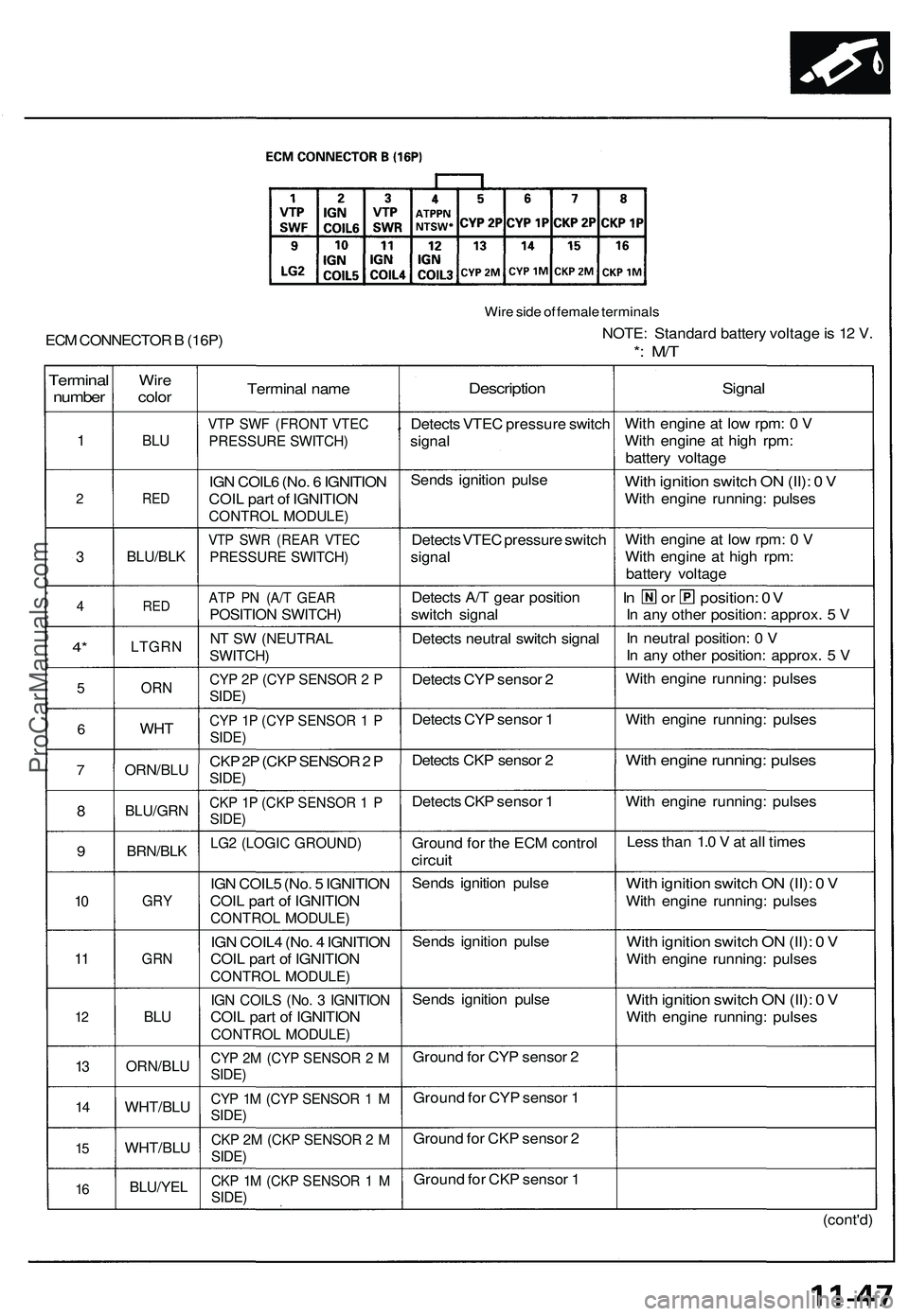
Wire side of female terminals
NOTE: Standard battery voltage is 12 V.
*: M/T
ECM CONNECTOR B (16P)ProCarManuals.com
Page 713 of 1503
Description
The automatic transmission is a combination of a 3-element torque converter and a triple-shaft electronically controlled
automatic transmission which provides 4 speeds forward and 1 speed reverse. The entire unit is positioned in line with the
engine.
Torque Converter, Gears, and Clutches
The torque converter consists of a pump, turbine, and stator, assembled in a single unit.
They are connected to the engine crankshaft so they turn together as a unit as the engine turns.
Around the outside of the torque converter is a ring gear which meshes with the starter pinion when the engine is being
started. The entire torque converter assembly serves as a flywheel while transmitting power to the transmission main-
shaft. The transmission has three parallel shafts: the mainshaft, the countershaft, and the secondary shaft. The mainshaft
is in line with the engine crankshaft.
The mainshaft includes the 1st and 4th clutches, and gears for 3rd, 4th, reverse, and 1st (3rd gear is integral with the main-
shaft, while reverse gear is integral with 4th gear).
The countershaft includes the 1st-hold and 3rd clutches, and gears for 2nd, 3rd, 4th, reverse, 1st, and parking.
The secondary shaft includes the 2nd clutch and gears for 2nd and 3rd.
The 4th and reverse gears can be locked to the countershaft at its center, providing 4th gear or reverse, depending on
which way the selector is moved.
The gears on the mainshaft and secondary shaft are in constant mesh with those on the countershaft.
When certain combinations of gears in the transmission are engaged by clutches, power is transmitted from the mainshaft
to the countershaft to provide positions.
Electronic Control
The electronic control system consists of the Transmission Control Module (TCM), sensors, a linear solenoid, a shift switch,
and 4 solenoid valves. Shifting and lock-up are electronically controlled for comfortable driving under all conditions.
The TCM is located on the insulator center bulkhead, behind the driver's seat.
Hydraulic Control
The valve bodies include the main valve body, secondary valve body, servo body, regulator valve body, throttle valve
body, lock-up valve body, and the 2nd accumulator body.
They are bolted to the torque converter housing as an assembly.
The main valve body contains the manual valve, 1-2 shift valve, 2-3 shift valve, 3-4 shift valve, relief valve, one-way relief
valve, and oil pump gears.
The secondary valve body contains the 3-2 kick-down valve, clutch pressure control (CPC) valve, 2nd orifice control valve, 3rd
orifice control valve, modulator valve, 4th exhaust valve, servo control valve, 2nd exhaust valve, and 4-3 kick-down valve.
The servo body contains the accumulator pistons and servo valve. The throttle valve body includes the throttle valve B
which is bolted to the servo body.
The regulator valve body contains the pressure regulator valve, lock-up control valve, and cooler relief valve. Fluid from
the regulator passes through the manual valve to the various control valves.
The lock-up valve body contains the lock-up timing B valve and lock-up shift valve. The 2nd accumulator body contains
the accumulator pistons and limited slip differential relief valve.
The torque converter check valve is located in the torque converter housing, under the main valve body.
The 1st, 1st-hold, 3rd, and 4th clutches receive fluid from their respective feed pipes and the 2nd clutch receives fluid from
the internal hydraulic circuit.
Shift Control Mechanism
Input from various sensors located throughout the vehicle determines which shift control solenoid valve the TCM will acti-
vate. Activating a shift control solenoid valve changes modulator pressure, causing a shift valve to move. This pressurizes
a line to one of the clutches, engaging that clutch and its corresponding gear.
Lock-up Mechanism
In position and position in 2nd, 3rd, and 4th, pressurized fluid is drained from the back of the torque converter
through a fluid passage, causing the lock-up piston to be held against the torque converter cover. As this takes place, the
mainshaft rotates at the same speed as the engine crankshaft. Together with hydraulic control, the TCM optimizes the tim-
ing of the lock-up mechanism.
The lock-up valves control the range of lock-up according to lock-up control solenoid valves A and B, and throttle valve B.
When lock-up control solenoid valves A and B activate, modulator pressure changes. The lock-up control solenoid valves
A and B are mounted on the torque converter housing, and are controlled by the TCM.
(cont'd)ProCarManuals.com
Page 776 of 1503
(cont'd)
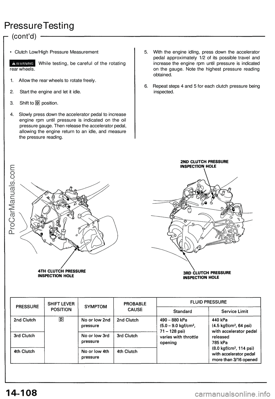
Pressure Testing
• Clutch Low/High Pressure Measurement
While testing, be careful of the rotating
rear wheels.
1. Allow the rear wheels to rotate freely.
2. Start the engine and let it idle.
3. Shift to position.
4. Slowly press down the accelerator pedal to increase
engine rpm until pressure is indicated on the oil
pressure gauge. Then release the accelerator pedal,
allowing the engine return to an idle, and measure
the pressure reading.
5. With the engine idling, press down the accelerator
pedal approximately 1/2 of its possible travel and
increase the engine rpm until pressure is indicated
on the gauge. Note the highest pressure reading
obtained.
6. Repeat steps 4 and 5 for each clutch pressure being
inspected.ProCarManuals.com
Page 780 of 1503
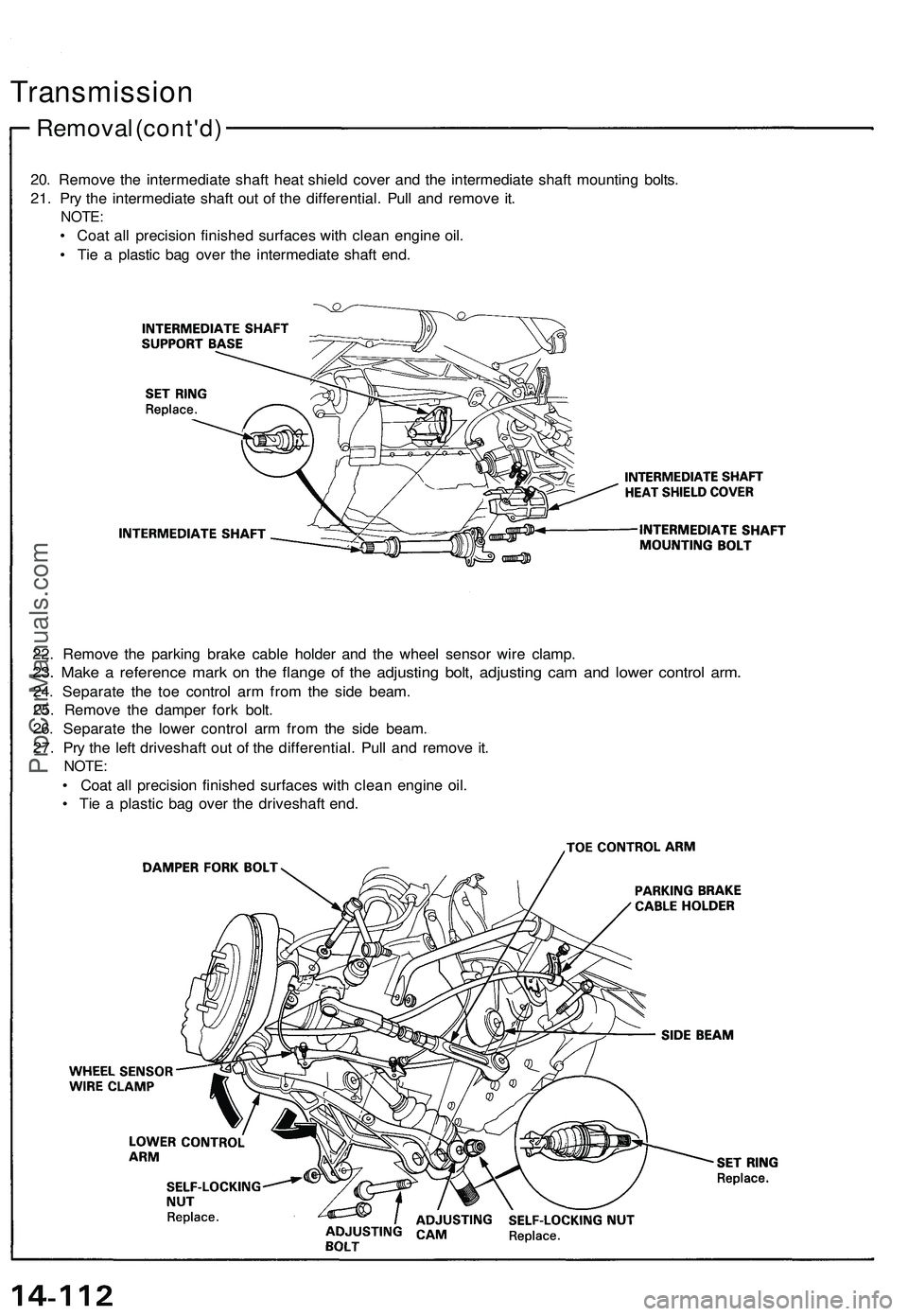
20. Remove the intermediate shaft heat shield cover and the intermediate shaft mounting bolts.
21. Pry the intermediate shaft out of the differential. Pull and remove it.
NOTE:
• Coat all precision finished surfaces with clean engine oil.
• Tie a plastic bag over the intermediate shaft end.
Removal (cont'd)
Transmission
22. Remove the parking brake cable holder and the wheel sensor wire clamp.
23. Make a reference mark on the flange of the adjusting bolt, adjusting cam and lower control arm.
24. Separate the toe control arm from the side beam.
25. Remove the damper fork bolt.
26. Separate the lower control arm from the side beam.
27. Pry the left driveshaft out of the differential. Pull and remove it.
NOTE:
• Coat all precision finished surfaces with clean engine oil.
• Tie a plastic bag over the driveshaft end.ProCarManuals.com
Page 1253 of 1503
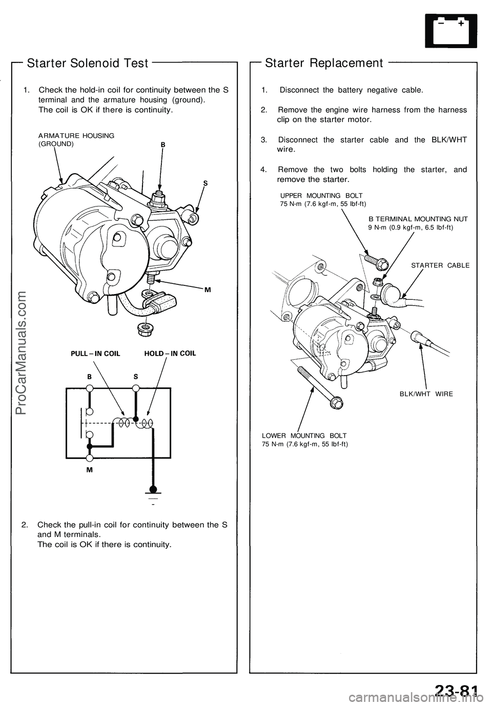
Starter Solenoid Test
1. Check the hold-in coil for continuity between the S
terminal and the armature housing (ground).
The coil is OK if there is continuity.
ARMATURE HOUSING
(GROUND)
2. Check the pull-in coil for continuity between the S
and M terminals.
The coil is OK if there is continuity.
Starter Replacement
1. Disconnect the battery negative cable.
2. Remove the engine wire harness from the harness
clip on the starter motor.
3. Disconnect the starter cable and the BLK/WHT
wire.
4. Remove the two bolts holding the starter, and
remove the starter.
UPPER MOUNTING BOLT
75 N-m (7.6 kgf-m, 55 Ibf-ft)
B TERMINAL MOUNTING NUT
9 N-m (0.9 kgf-m, 6.5 Ibf-ft)
STARTER CABLE
LOWER MOUNTING BOLT
75 N-m (7.6 kgf-m, 55 Ibf-ft)
BLK/WHT WIREProCarManuals.com