Page 1096 of 1399

Z15178
Matchmarks
SA2464
W03472
SST
RA0997
FA2046
Matchmarks
−
SUSPENSION AND AXLE FRONT DIFFERENTIAL CARRIER
SA−33
1996 LAND CRUISER (RM451U)
18. REMOVE RING GEAR
(a) Using a screwdriver and hammer, unstake the lock plate.
(b) Place matchmarks on the ring gear and differential case.
(c) Remove the ring gear 10 set bolts and 5 lock plates.
(d) Using a plastic hammer, tap on the ring gear to separate
it from the differential case.
19. CHECK DIFFERENTIAL CASE RUNOUT
(a) Install the differential case in the differential carrier and tighten the adjusting nut just to where there is no play in
the bearing.
(b) Using a dial indicator, measure the differential case run- out.
Maximum case runout: 0.07 mm (0.0028 in.)
(c) Remove the differential case.
20. REMOVE SIDE BEARING FROM DIFFERENTIAL CASE
Using SST, pull the side bearing from the differential case. SST 09950 −40010 (09951 −04010, 09952 −04020,
09953 −04020, 09954 −04010, 09955 −04010,
09957 −04010, 09958 −04010),
09950 −60010 (09951 −00480)
HINT:
Fix the claws of SST to the notches in the differential case.
21. w/o DIFFERENTIAL LOCK: DISASSEMBLE DIFFERENTIAL CASE
(a) Using a pin punch and hammer, remove the straight pin.
(b) Remove these parts from the differential case:
�Pinion shaft
�2 Pinion gears
�2 Pinion gear thrust washers
�2 Side gears
�2 Side gear thrust washers
22. w/ DIFFERENTIAL LOCK: DISASSEMBLE DIFFERENTIAL CASE
(a) Place matchmarks on the LH and RH cases.
(b) Remove the 8 bolts uniformly, a little at a time.
(c) Using a plastic hammer, separate the LH and RH cases.
(d) Remove these parts from the RH differential case:
�2 Side gears
�2 Side gear thrust washers
�Spider
Brought to you by BirfMark
Brought to you by BirfMark
Version 1.11 - 03/16/2010
Page 1097 of 1399
SA−34
−
SUSPENSION AND AXLE FRONT DIFFERENTIAL CARRIER
1996 LAND CRUISER (RM451U)
�4 Pinion gears
�4 Pinion gear thrust washers
Brought to you by BirfMark
Brought to you by BirfMark
Version 1.11 - 03/16/2010
Page 1099 of 1399
SA0510
SA1UP−03
Z06893
Z06894
R08149
SA−36
−
SUSPENSION AND AXLE FRONT DIFFERENTIAL CARRIER
1996 LAND CRUISER (RM451U)
REASSEMBLY
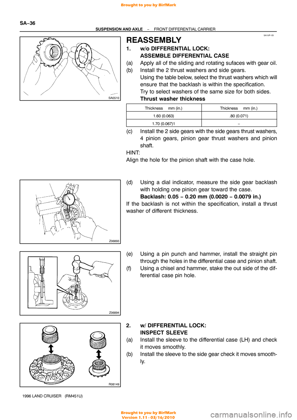
1. w/o DIFFERENTIAL LOCK: ASSEMBLE DIFFERENTIAL CASE
(a) Apply all of the sliding and rotating sufaces with gear oil.
(b) Install the 2 thrust washers and side gears. Using the table below, select the thrust washers which will
ensure that the backlash is within the specification.
Try to select washers of the same size for both sides.
Thrust washer thickness
Thickness mm (in.)Thickness mm (in.)
1.60 (0.063).80 (0.071)
1.70 (0.067)1−
(c) Install the 2 side gears with the side gears thrust washers,
4 pinion gears, pinion gear thrust washers and pinion
shaft.
HINT:
Align the hole for the pinion shaft with the case hole.
(d) Using a dial indicator, measure the side gear backlash with holding one pinion gear toward the case.
Backlash: 0.05 − 0.20 mm (0.0020 − 0.0079 in.)
If the backlash is not within the specification, install a thrust
washer of different thickness.
(e) Using a pin punch and hammer, install the straight pin through the holes in the dif ferential case and pinion shaft.
(f) Using a chisel and hammer, stake the out side of the dif- ferential case pin hole.
2. w/ DIFFERENTIAL LOCK: INSPECT SLEEVE
(a) Install the sleeve to the differential case (LH) and check
it moves smoothly.
(b) Install the sleeve to the side gear check it moves smooth-
ly.
Brought to you by BirfMark
Brought to you by BirfMark
Version 1.11 - 03/16/2010
Page 1100 of 1399
SA1987
SA1978
SA1976
FA2037
−
SUSPENSION AND AXLE FRONT DIFFERENTIAL CARRIER
SA−37
1996 LAND CRUISER (RM451U)
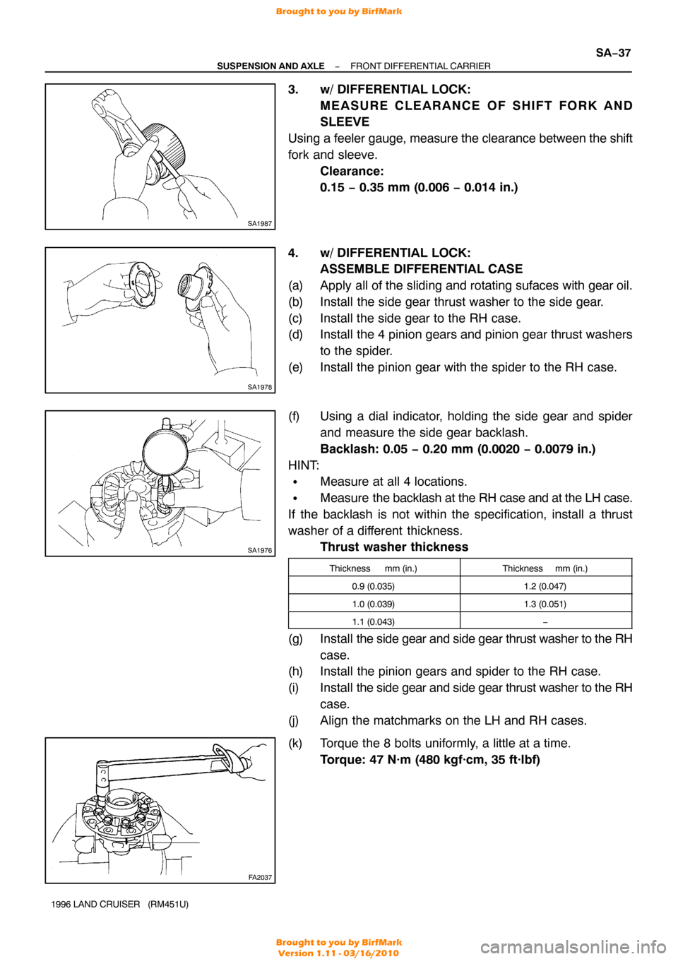
3. w/ DIFFERENTIAL LOCK:
MEASURE CLEARANCE OF SHIFT FORK AND
SLEEVE
Using a feeler gauge, measure the clearance between the shift
fork and sleeve. Clearance:
0.15 − 0.35 mm (0.006 − 0.014 in.)
4. w/ DIFFERENTIAL LOCK: ASSEMBLE DIFFERENTIAL CASE
(a) Apply all of the sliding and rotating sufaces with gear oil.
(b) Install the side gear thrust washer to the side gear.
(c) Install the side gear to the RH case.
(d) Install the 4 pinion gears and pinion gear thrust washers to the spider.
(e) Install the pinion gear with the spider to the RH case.
(f) Using a dial indicator, holding the side gear and spider and measure the side gear backlash.
Backlash: 0.05 − 0.20 mm (0.0020 − 0.0079 in.)
HINT:
�Measure at all 4 locations.
�Measure the backlash at the RH case and at the LH case.
If the backlash is not within the specification, install a thrust
washer of a different thickness. Thrust washer thickness
Thickness mm (in.)Thickness mm (in.)
0.9 (0.035)1.2 (0.047)
1.0 (0.039)1.3 (0.051)
1.1 (0.043)−
(g) Install the side gear and side gear thrust washer to the RH
case.
(h) Install the pinion gears and spider to the RH case.
(i) Install the side gear and side gear thrust washer to the RH
case.
(j) Align the matchmarks on the LH and RH cases.
(k) Torque the 8 bolts uniformly, a little at a time. Torque: 47 N·m (480 kgf·cm, 35 ft·lbf)
Brought to you by BirfMark
Brought to you by BirfMark
Version 1.11 - 03/16/2010
Page 1102 of 1399
SA2465
SA2406
SST
SA2203
SSTSST
Front
Rear
FA2042
SST
R13140
SST
−
SUSPENSION AND AXLE FRONT DIFFERENTIAL CARRIER
SA−39
1996 LAND CRUISER (RM451U)
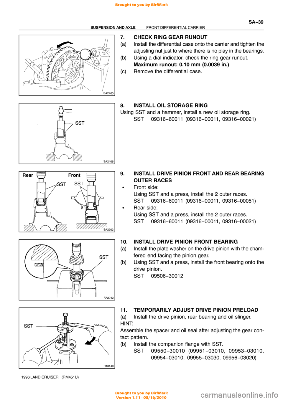
7. CHECK RING GEAR RUNOUT
(a) Install the differential case onto the carrier and tighten the
adjusting nut just to where there is no play in the bearings.
(b) Using a dial indicator, check the ring gear runout. Maximum runout: 0.10 mm (0.0039 in.)
(c) Remove the differential case.
8. INSTALL OIL STORAGE RING
Using SST and a hammer, install a new oil storage ring. SST 09316−60011 (09316 −00011, 09316−00021)
9. INSTALL DRIVE PINION FRONT AND REAR BEARING
OUTER RACES
�Front side:
Using SST and a press, install the 2 outer races.
SST 09316−60011 (09316 −00011, 09316−00051)
�Rear side:
Using SST and a press, install the 2 outer races.
SST 09316−60011 (09316 −00011, 09316−00021)
10. INSTALL DRIVE PINION FRONT BEARING
(a) Install the plate washer on the drive pinion with the cham-
fered end facing the pinion gear.
(b) Using SST and a press, install the front bearing onto the
drive pinion.
SST 09506−30012
11. TEMPORARILY ADJUST DRIVE PINION PRELOAD
(a) Install the drive pinion, rear bearing and oil slinger.
HINT:
Assemble the spacer and oil seal after adjusting the gear con-
tact pattern.
(b) Install the companion flange with SST. SST 09550 −30010 (09951 −03010, 09953 −03010,
09954 −03010, 09955 −03030, 09956−03020)
Brought to you by BirfMark
Brought to you by BirfMark
Version 1.11 - 03/16/2010
Page 1105 of 1399
SA2443SST
SA2403
SA2463
FA2013
Proper ContactHeel Contact
Face Contact
Select an adjusting washer that will bring the drive
pinion closer to the ring gear.
Select an adjusting washer that will shift the drive
pinion away from the ring gear.
Toe Contact
Flank Contact
SA−42
−
SUSPENSION AND AXLE FRONT DIFFERENTIAL CARRIER
1996 LAND CRUISER (RM451U)
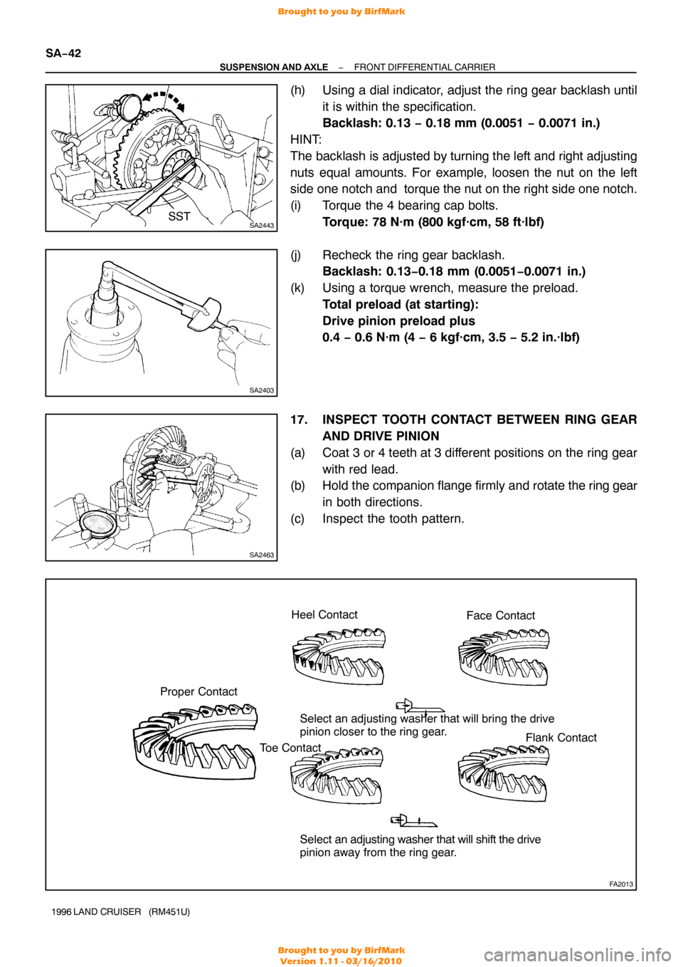
(h) Using a dial indicator, adjust the ring gear backlash until
it is within the specification.
Backlash: 0.13 − 0.18 mm (0.0051 − 0.0071 in.)
HINT:
The backlash is adjusted by turning the left and right adjusting
nuts equal amounts. For example, loosen the nut on the left
side one notch and torque the nut on the right side one notch.
(i) Torque the 4 bearing cap bolts. Torque: 78 N·m (800 kgf·cm, 58 ft·lbf)
(j) Recheck the ring gear backlash. Backlash: 0.13 −0.18 mm (0.0051 −0.0071 in.)
(k) Using a torque wrench, measure the preload. Total preload (at starting):
Drive pinion preload plus
0.4 − 0.6 N·m (4 − 6 kgf·cm, 3.5 − 5.2 in.·lbf)
17. INSPECT TOOTH CONTACT BETWEEN RING GEAR AND DRIVE PINION
(a) Coat 3 or 4 teeth at 3 different positions on the ring gear with red lead.
(b) Hold the companion flange firmly and rotate the ring gear
in both directions.
(c) Inspect the tooth pattern.
Brought to you by BirfMark
Brought to you by BirfMark
Version 1.11 - 03/16/2010
Page 1106 of 1399
FA2041
Washer
W00529
SA2407
SST
R13140
SST
−
SUSPENSION AND AXLE FRONT DIFFERENTIAL CARRIER
SA−43
1996 LAND CRUISER (RM451U)
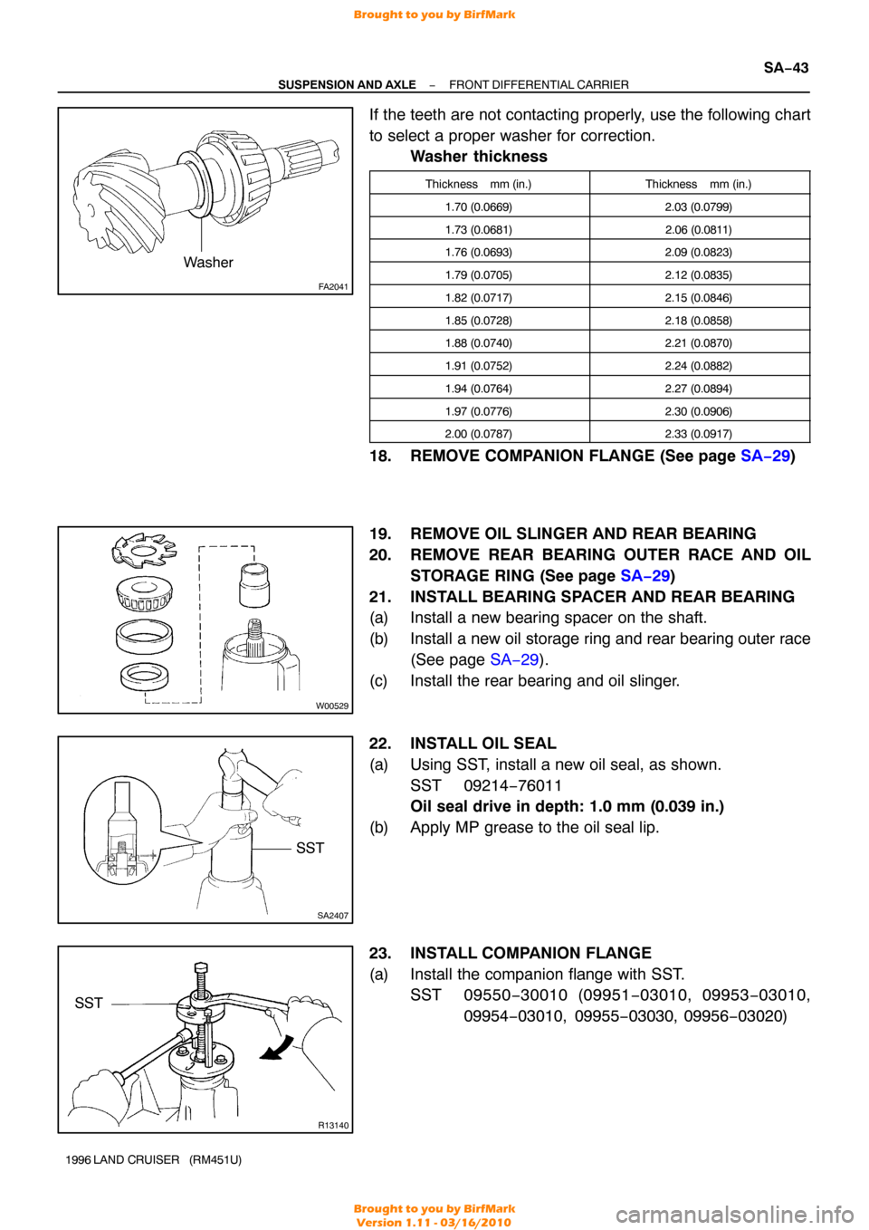
If the teeth are not contacting properly, use the following chart
to select a proper washer for correction.
Washer thickness
Thickness mm (in.)Thickness mm (in.)
1.70 (0.0669)2.03 (0.0799)
1.73 (0.0681)2.06 (0.0811)
1.76 (0.0693)2.09 (0.0823)
1.79 (0.0705)2.12 (0.0835)
1.82 (0.0717)2.15 (0.0846)
1.85 (0.0728)2.18 (0.0858)
1.88 (0.0740)2.21 (0.0870)
1.91 (0.0752)2.24 (0.0882)
1.94 (0.0764)2.27 (0.0894)
1.97 (0.0776)2.30 (0.0906)
2.00 (0.0787)2.33 (0.0917)
18. REMOVE COMPANION FLANGE (See page SA−29)
19. REMOVE OIL SLINGER AND REAR BEARING
20. REMOVE REAR BEARING OUTER RACE AND OIL STORAGE RING (See page SA−29 )
21. INSTALL BEARING SPACER AND REAR BEARING
(a) Install a new bearing spacer on the shaft.
(b) Install a new oil storage ring and rear bearing outer race (See page SA−29 ).
(c) Install the rear bearing and oil slinger.
22. INSTALL OIL SEAL
(a) Using SST, install a new oil seal, as shown. SST 09214−76011
Oil seal drive in depth: 1.0 mm (0.039 in.)
(b) Apply MP grease to the oil seal lip.
23. INSTALL COMPANION FLANGE
(a) Install the companion flange with SST. SST 09550 −30010 (09951 −03010, 09953 −03010,
09954 −03010, 09955 −03030, 09956−03020)
Brought to you by BirfMark
Brought to you by BirfMark
Version 1.11 - 03/16/2010
Page 1107 of 1399
SA2390
SST
SA2403
SA2471
SA−44
−
SUSPENSION AND AXLE FRONT DIFFERENTIAL CARRIER
1996 LAND CRUISER (RM451U)
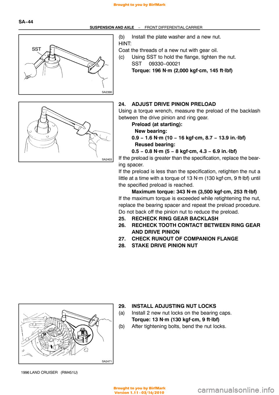
(b) Install the plate washer and a new nut.
HINT:
Coat the threads of a new nut with gear oil.
(c) Using SST to hold the flange, tighten the nut.
SST 09330−00021
Torque: 196 N·m (2,000 kgf·cm, 145 ft·lbf)
24. ADJUST DRIVE PINION PRELOAD
Using a torque wrench, measure the preload of the backlash
between the drive pinion and ring gear. Preload (at starting):
New bearing:
0.9 − 1.6 N·m (10 − 16 kgf·cm, 8.7 − 13.9 in.·lbf)
Reused bearing:
0.5 − 0.8 N·m (5 − 8 kgf·cm, 4.3 − 6.9 in.·lbf)
If the preload is greater than the specification, replace the bear-
ing spacer.
If the preload is less than the specification, retighten the nut a
little at a time with a torque of 13 N·m (130 kgf·cm, 9 ft·lbf) until
the specified preload is reached. Maximum torque: 343 N·m (3,500 kgf·cm, 253 ft·lbf)
If the maximum torque is exceeded while retightening the nut,
replace the bearing spacer and repeat the preload procedure.
Do not back off the pinion nut to reduce the preload.
25. RECHECK RING GEAR BACKLASH
26. RECHECK TOOTH CONTACT BETWEEN RING GEAR
AND DRIVE PINION
27. CHECK RUNOUT OF COMPANION FLANGE
28. STAKE DRIVE PINION NUT
29. INSTALL ADJUSTING NUT LOCKS
(a) Install 2 new nut locks on the bearing caps. Torque: 13 N·m (130 kgf·cm, 9 ft·lbf)
(b) After tightening bolts, bend the nut locks.
Brought to you by BirfMark
Brought to you by BirfMark
Version 1.11 - 03/16/2010