Page 374 of 1399

−
BRAKE PARKING BRAKE
BR−41
1996 LAND CRUISER (RM451U)
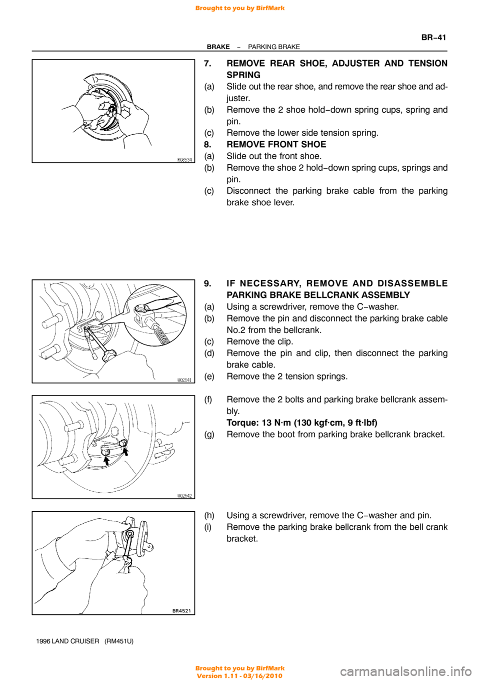
7. REMOVE REAR SHOE, ADJUSTER AND TENSION
SPRING
(a) Slide out the rear shoe, and remove the rear shoe and ad-
juster.
(b) Remove the 2 shoe hold −down spring cups, spring and
pin.
(c) Remove the lower side tension spring.
8. REMOVE FRONT SHOE
(a) Slide out the front shoe.
(b) Remove the shoe 2 hold −down spring cups, springs and
pin.
(c) Disconnect the parking brake cable from the parking
brake shoe lever.
9. IF NECESSARY, REMOVE AND DISASSEMBLE PARKING BRAKE BELLCRANK ASSEMBLY
(a) Using a screwdriver, remove the C −washer.
(b) Remove the pin and disconnect the parking brake cable No.2 from the bellcrank.
(c) Remove the clip.
(d) Remove the pin and clip, then disconnect the parking
brake cable.
(e) Remove the 2 tension springs.
(f) Remove the 2 bolts and parking brake bellcrank assem- bly.
Torque: 13 N·m (130 kgf·cm, 9 ft·lbf)
(g) Remove the boot from parking brake bellcrank bracket.
(h) Using a screwdriver, remove the C −washer and pin.
(i) Remove the parking brake bellcrank from the bell crank bracket.
Brought to you by BirfMark
Brought to you by BirfMark
Version 1.11 - 03/16/2010
Page 376 of 1399
−
BRAKE PARKING BRAKE
BR−43
1996 LAND CRUISER (RM451U)
6. IF NECESSARY, REPLACE SHIM
(a) Using a screwdriver, remove the C −washer.
(b) Remove the park ing brake shoe lever, and install the cor-
rect size shim.
(c) Using needle −nose pliers, install the parking brake shoe
lever with a new C −washer.
(d) Remeasure the clearance.
Brought to you by BirfMark
Brought to you by BirfMark
Version 1.11 - 03/16/2010
Page 382 of 1399
BR1DE−01
−
BRAKE LOAD SENSING PROPORTIONING AND BY− PASS
VALVE (LSP & BV)BR−49
1996 LAND CRUISER (RM451U)
DISASSEMBLY
1. REMOVE VALVE BRACKET
(a) Remove the nut, bolt and 2 plate washers.
(b) Remove the 2 nuts, bracket and set plate from the valve
body.
2. DISCONNECT SPRING FROM VALVE
Using pliers, remove the clip, and remove the spring from the
valve.
3. REMOVE SHACKLE NO.1 AND NO.2
(a) Remove the bolt and nut, then remove the these parts:
�Load sensing spring
�2 plate washers
(b) Loosen the 2 nuts, and remove the shackle No.1 from the
shackle No.2.
4. DISASSEMBLE LOAD SENSING SPRING
Disassembly the these parts:
�4 bushings
�2 collars
�2 rubber plates
�Load sensing valve boot
�Load sensing spring boot
Brought to you by BirfMark
Brought to you by BirfMark
Version 1.11 - 03/16/2010
Page 384 of 1399

BR1DG−01
BR0070
−
BRAKE LOAD SENSING PROPORTIONING AND BY− PASS
VALVE (LSP & BV)BR−51
1996 LAND CRUISER (RM451U)
REASSEMBLY
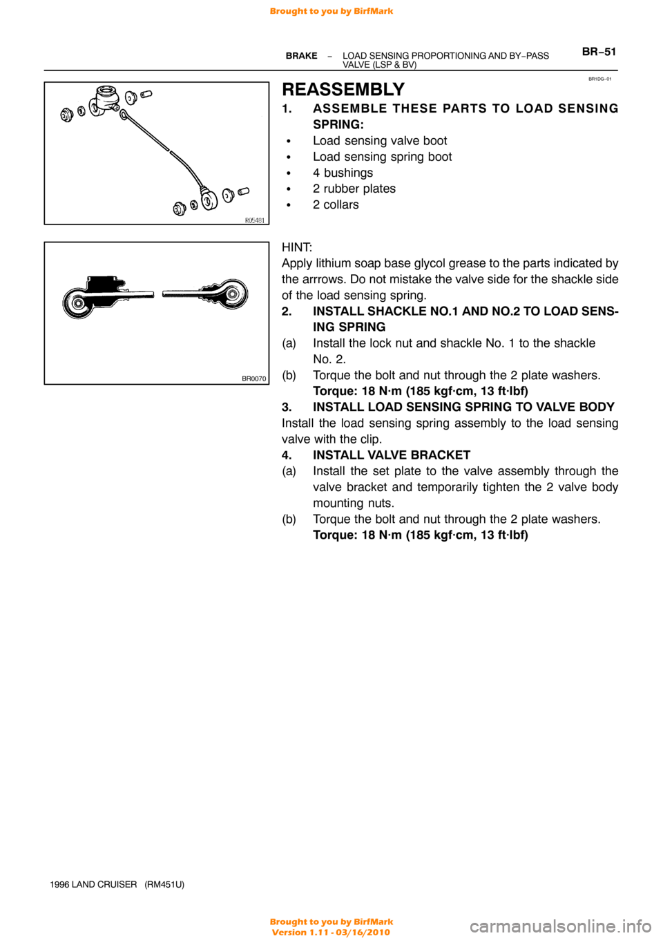
1. ASSEMBLE THESE PARTS TO LOAD SENSING
SPRING:
�Load sensing valve boot
�Load sensing spring boot
�4 bushings
�2 rubber plates
�2 collars
HINT:
Apply lithium soap base glycol grease to the parts indicated by
the arrrows. Do not mistake the valve side for the shackle side
of the load sensing spring.
2. INSTALL SHACKLE NO.1 AND NO.2 TO LOAD SENS-
ING SPRING
(a) Install the lock nut and shackle No. 1 to the shackle No. 2.
(b) Torque the bolt and nut through the 2 plate washers. Torque: 18 N·m (185 kgf·cm, 13 ft·lbf)
3. INSTALL LOAD SENSING SPRING TO VALVE BODY
Install the load sensing spring assembly to the load sensing
valve with the clip.
4. INSTALL VALVE BRACKET
(a) Install the set plate to the valve assembly through the valve bracket and temporarily tighten the 2 valve body
mounting nuts.
(b) Torque the bolt and nut through the 2 plate washers. Torque: 18 N·m (185 kgf·cm, 13 ft·lbf)
Brought to you by BirfMark
Brought to you by BirfMark
Version 1.11 - 03/16/2010
Page 413 of 1399
P08243
SST (C)Turn
SST (A)
P03794
−
CHARGING GENERATOR
CH−11
1996 LAND CRUISER (RM451U)
(e) To loosen the pulley nut, turn SST (A) in the direction
shown in the illustration.
NOTICE:
To prevent damage to the rotor shaft, do not loosen the
pulley nut more than one −half of a turn.
(f) Remove the generator from SST (C).
(g) Turn SST (B) and remove SST (A and B).
(h) Remove the pulley nut and pulley.
6. REMOVE RECTIFIER END FRAME
(a) Remove the 4 nuts.
(b) Using SST, remove the rectifier end frame. SST 09286−46011
(c) Remove the generator washer.
7. REMOVE ROTOR FROM DRIVE END FRAME
Brought to you by BirfMark
Brought to you by BirfMark
Version 1.11 - 03/16/2010
Page 418 of 1399
P03802
CH06M−03
P03794
P03807
Hold SST (A)
SST (B)
Turn
P08242
SST (C)
CH−16
−
CHARGING GENERATOR
1996 LAND CRUISER (RM451U)
REASSEMBLY
1. PLACE RECTIFIER END FRAME ON PULLEY
2. INSTALL ROTOR TO DRIVE END FRAME
3. INSTALL RECTIFIER END FRAME
(a) Place the generator washer on the rotor.
(b) Using a 29 mm socket wrench and press, slowly press in
the rectifier end frame.
(c) Install the 4 nuts. Torque: 4.5 N·m (46 kgf·cm, 40 in.·lbf)
4. INSTALL PULLEY
(a) Install the pulley to the rotor shaft by tightening the pulley
nut by hand.
(b) Hold SST (A) with a torque wrench, and tighten SST (B)
clockwise to the specified torque.
SST 09820−63010
Torque: 39 N·m (400 kgf·cm, 29 ft·lbf)
(c) Check that SST (A) is secured to the pulley shaft.
(d) Mount SST (C) in a vise.
(e) Install the generator to SST (C).
Brought to you by BirfMark
Brought to you by BirfMark
Version 1.11 - 03/16/2010
Page 821 of 1399
EM−36
−
ENGINE MECHANICAL CYLINDER HEAD
1996 LAND CRUISER (RM451U)
(e) Remove the wave washer (1), camshaft sub− gear (2) and
camshaft gear spring (3).
37. REMOVE CYLINDER HEAD AND INTAKE MANIFOLD ASSEMBLY
(a) Remove the 2 bolts in front of the head before the other head bolts are removed.
(b) Uniformly loosen and remove the 14 cylinder head bolts, in several passes, in the sequence shown.
NOTICE:
Cylinder head warpage or cracking could result from re-
moving bolts in incorrect order.
(c) Lift the cylinder head from the dowels on the cylinder block, and place the cylinder head on wooden blocks on
a bench.
HINT:
If the cylinder head is difficult to lift off, pry between the cylinder
head and cylinder block with a screwdriver.
NOTICE:
Be careful not to damage the contact surfaces of the cylin-
der head and cylinder block.
Brought to you by BirfMark
Brought to you by BirfMark
Version 1.11 - 03/16/2010
Page 839 of 1399

EM1E7−01
EM−54
−
ENGINE MECHANICAL CYLINDER HEAD
1996 LAND CRUISER (RM451U)
INSTALLATION
1. INSTALL CYLINDER HEAD AND INTAKE MANIFOLD ASSEMBLY
(a) Place the cylinder head on the cylinder head. (1) Apply seal packing to the 2 locations as shown.
Seal packing: Part No. 08826−00080 or equivalent
NOTICE:
Do not apply too much seal packing
(2) Place a new cylinder head gasket in position on the
cylinder block.
NOTICE:
Be careful of the installation direction. (3) Place the cylinder head in position on the cylinderhead gasket.
(b) Install the cylinder head bolts.
HINT:
�The cylinder head bolts are tightened in 3 progressive
steps (steps (b), (d) and (e)).
�If any cylinder head bolt is broken or deformed, replace
it.
(1) Apply a light coat of engine oil on the threads and under the heads of the cylinder head bolts.
(2) Install and uniformly tighten the 14 cylinder head
bolts and plate washers in several passes, in the se-
quence shown.
Torque: 39 N·m (400 kgf·cm, 29 ft·lbf)
If any of the cylinder head bolts does not meet the torque speci-
fication, replace the cylinder head bolt.
(3) Mark the front of the cylinder head bolt head withpaint.
(4) Retighten the cylinder head bolts by 90 ° in the nu-
merical order shown.
(5) Retighten the cylinder head bolts by an additional 90°.
(6) Check that the painted mark is now facing rearward.
Brought to you by BirfMark
Brought to you by BirfMark
Version 1.11 - 03/16/2010