Page 8 of 1399

IN0253
WRONGCORRECT
IN0252
WRONGCORRECT
IN−6
−
INTRODUCTION REPAIR INSTRUCTIONS
6
Author�: Date�:
1996 LAND CRUISER (RM451U)
(k) Care must be taken when jacking up and supporting the
vehicle. Be sure to lift and support the vehicle at the prop-
er locations (See page IN−8).
�Cancel the parking brake on the level place and
shift the transmission in Neutral (or N position).
�When jacking up the front wheels of the vehicle at
first place stoppers behind the rear wheels.
�When jacking up the rear wheels of the vehicle at
first place stoppers before the front wheels.
�When either the front or rear wheels only should be
jacked up, set rigid racks and place stoppers in front
and behind the other wheels on the ground.
�After the vehicle is jacked up, be sure to support it
on rigid racks . It is extremely dangerous to do any
work on a vehicle raised on a jack alone, even for
a small job that can be finished quickly.
(l) Observe the following precautions to avoid damage to the
following parts:
(1) Do not open the cover or case of the ECU unless absolutely necessary. (If the IC terminals are
touched, the IC may be destroyed by static electric-
ity.)
(2) To disconnect vacuum hoses, pull off the end, not the middle of the hose.
(3) To pull apart electrical connectors, pull on the con- nector itself, not the wires.
(4) Be careful not to drop electrical components, such
as sensors or relays. If they are dropped on a hard
floor, they should be replaced and not reused.
(5) When steam cleaning an engine, protect the elec- tronic components, air filter and emission −related
components from water.
(6) Never use an impact wrench to remove or install temperature switches or temperature sensors.
Brought to you by BirfMark
Brought to you by BirfMark
Version 1.11 - 03/16/2010
Page 16 of 1399

V08127
IN−14
−
INTRODUCTION FOR ALL OF VEHICLES
14
Author�: Date�:
1996 LAND CRUISER (RM451U)
2. WHEN TOWING FULL −TIME 4WD VEHICLES
�Use one of the methods shown below to tow the vehicle.
�If the vehicle has trouble in the chassis and drive train, use method 1 \
(flat bed truck).
TransmissionTransfer(w/oASS)
~
Parking
ShiftLever
ShiftLever Center
Center
Towing Method Brake
Position PositionDifferential
Differential
Lock Switch
CDFlatSed Truck
~
IN0309
@WheelLiftType Truck with
Dollies FREE
Applied
lipIIRangeIIHIIPosition OFF(Normal)
~
Driving
ii-;~
@TowingwithRope
L~
ReleasedlINIIRangeIIN/IPosition
OFFt
IN0312
HINT:Donotuse anytowing methods otherthanthose shown above.
Forexample, thetowing method shownbelowisdangerous, sodo not use it.
NO
~
IN0313
During towing withthistowing method, thereisadanger of thedrivetrain
heating upand causing breakdown, orofthe front wheels flyingoffthe
dolly.
\�127
Brought to you by BirfMark
Brought to you by BirfMark
Version 1.11 - 03/16/2010
Page 36 of 1399

IN−34
−
INTRODUCTION TERMS
34
Author�: Date�:
1996 LAND CRUISER (RM451U)
CW
Curb W
eight
DCDirect Current
DEFDefogger
DFLDeflector
DIFF.Differential
DIFF. LOCKDifferential Lock
D/INJDirect Injection
DLIDistributorless Ignition
DOHCDouble Over Head Cam
DPDash Pot
DSDead Soak
DSPDigital Signal Processor
EBDElectronic Brake Force Distribution
ECAMEngine Control And Measurement System
ECDElectronic Controlled Diesel
ECDYEddy Current Dynamometer
ECUElectronic Control Unit
EDElectro−Deposited Coating
EDICElectric Diesel Injection Control
EDUElectronic Driving Unit
EFIElectronic Fuel Injection
E/GEngine
EGR−VMExhaust Gas Recirculation −Vacuum Modulator
ELREmergency Locking Retractor
ENGEngine
ESAElectronic Spark Advance
ETCSElectronic Throttle Control System
EVPEvaporator
E−VRVElectric V acuum Regulating V alve
EXHExhaust
FEFuel Economy
FFFront−Engine Front− Wheel−Drive
F/GFuel Gage
FIPGFormed In Place Gasket
FLFusible Link
F/PFuel Pump
FPUFuel Pressure Up
FrFront
FRFront−Engine Rear− Wheel−Drive
F/WFlywheel
FW/DFlywheel Damper
FWDFront−Wheel−Drive
GASGasoline
GSAGear Shift Actuator
GNDGround
HACHigh Altitude Compensator
Brought to you by BirfMark
Brought to you by BirfMark
Version 1.11 - 03/16/2010
Page 38 of 1399

IN−36
−
INTRODUCTION TERMS
36
Author�: Date�:
1996 LAND CRUISER (RM451U)
NA
Natural Aspiration
No.Number
O/DOverdrive
OEMOriginal Equipment Manufacturing
OHCOverhead Camshaft
OHVOverhead V
alve
OPTOption
O/SOversize
P & BVProportioning And Bypass Valve
PCSPower Control System
PCVPositive Crankcase Ventilation
PKBParking Brake
PPSProgressive Power Steering
PSPower Steering
PTOPower Take−Off
R & PRack And Pinion
R/BRelay Block
RBSRecirculating Ball Type Steering
R/FReinforcement
RFSRigid Front Suspension
RHRight−Hand
RHDRight−Hand Drive
RLYRelay
ROMRead Only Memory
RrRear
RRRear−Engine Rear −Wheel Drive
RRSRigid Rear Suspension
RWDRear− Wheel Drive
SDNSedan
SENSensor
SICSStarting Injection Control System
SMTSequential Manual T ransmission
SOCState Of Charge
SOHCSingle Overhead Camshaft
SPECSpecification
SPISingle Point Injection
SRSSupplemental Restraint System
SSMSpecial Service Materials
SSTSpecial Service Tools
STDStandard
STJCold−Start Fuel Injection
SWSwitch
SYSSystem
T/ATransaxle
TACHTachometer
TBIThrottle Body Electronic Fuel Injection
Brought to you by BirfMark
Brought to you by BirfMark
Version 1.11 - 03/16/2010
Page 121 of 1399
AT0SZ−01
V07130
Shift Lever PositionGear PositionParkingC0C1C2B0B1B2B3F0F1F2
Reverse
Neutral 1st
2nd
3rd
O/D
P
R
N
D
2
L
1st
2nd
*1
3rd
1st
*2 2nd
Operating
*1 Down− shift only in the 2 position and 3rd gear −no up− shift.
*2 Down− shift only in the L position and 2nd gear −no up− shift.
O/D Direct
Clutch (C
0)
2nd Coast Brake (B1)
O/D Brake (B
0) Direct
Clutch (C2)
Forward Clutch (C
1)
2nd Brake (B
2)
1st & Reverse
Brake (B
3)
Rear Planetary Carrier
Rear Planetary Ring Gear
Output Shaft
Front & Rear Planetary
Sun Gear
No.2 One−Way
Clutch (F
2)
No.1 One−Way
Clutch (F
1)
Front Planetary
Ring Gear
Front Planetary
Carrier
O/D Planetary
Ring Gear
O/D Planetary
Carrier
O/D Planetary
Sun Gear
Input Shaft
O/D Input Shaft
O/D One−Way
Clutch (F
0)
AT−2
−
AUTOMATIC TRANSMISSION AUTOMATIC TRANSMISSION SYSTEM
1996 LAND CRUISER (RM451U)
OPERATION
Brought to you by BirfMark
Brought to you by BirfMark
Version 1.11 - 03/16/2010
Page 143 of 1399

Q07409
AT−24
−
AUTOMATIC TRANSMISSION AUTOMATIC TRANSMISSION UNIT
1996 LAND CRUISER (RM451U)
(d) Remove the 4 nuts and 2 gaskets, shift the front exhaust
pipe assembly to the vehicle’s outside.
Torque: 62 N·m (630 kgf·cm, 46 ft·lbf)
HINT:
At the time of installation, replace the used gaskets and nuts
with new gaskets and nuts.
15. REMOVE STARTER
(a) Remove the nut and disconnect the terminal and connec-
tor.
(b) Remove the lower side mounting bolt and starter. Torque: 39 N·m (400 kgf·cm, 29 ft·lbf)
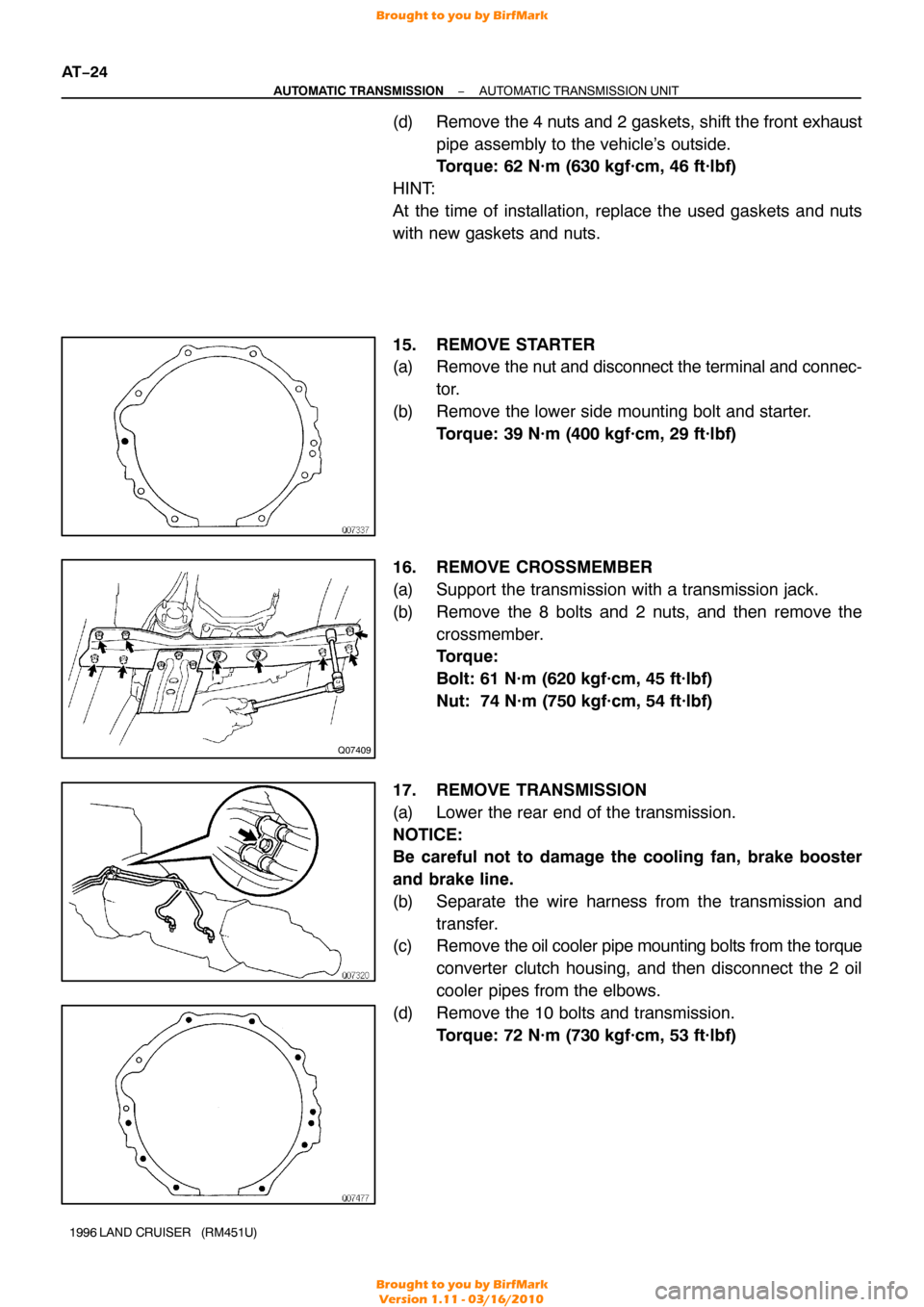
16. REMOVE CROSSMEMBER
(a) Support the transmission with a transmission jack.
(b) Remove the 8 bolts and 2 nuts, and then remove the crossmember.
Torque:
Bolt: 61 N·m (620 kgf·cm, 45 ft·lbf)
Nut: 74 N·m (750 kgf·cm, 54 ft·lbf)
17. REMOVE TRANSMISSION
(a) Lower the rear end of the transmission.
NOTICE:
Be careful not to damage the cooling fan, brake booster
and brake line.
(b) Separate the wire harness from the transmission and transfer.
(c) Remove the oil cooler pipe mounting bolts from the torque
converter clutch housing, and then disconnect the 2 oil
cooler pipes from the elbows.
(d) Remove the 10 bolts and transmission. Torque: 72 N·m (730 kgf·cm, 53 ft·lbf)
Brought to you by BirfMark
Brought to you by BirfMark
Version 1.11 - 03/16/2010
Page 354 of 1399
BR1CR−01
−
BRAKE FRONT BRAKE PAD
BR−21
1003
Author�: Date�:
1996 LAND CRUISER (RM451U)
FRONT BRAKE PAD
COMPONENTS
Brought to you by BirfMark
Brought to you by BirfMark
Version 1.11 - 03/16/2010
Page 355 of 1399

BR1CS−04
BR−22
−
BRAKE FRONT BRAKE PAD
1996 LAND CRUISER (RM451U)
REPLACEMENT
1. REMOVE FRONT WHEEL
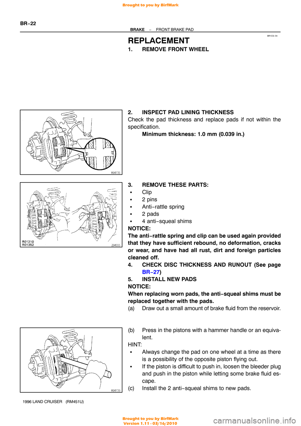
2. INSPECT PAD LINING THICKNESS
Check the pad thickness and replace pads if not within the
specification. Minimum thickness: 1.0 mm (0.039 in.)
3. REMOVE THESE PARTS:
�Clip
�2 pins
�Anti−rattle spring
�2 pads
�4 anti−squeal shims
NOTICE:
The anti −rattle spring and clip can be used again provided
that they have sufficient rebound, no deformation, cracks
or wear, and have had all rust, dirt and foreign particles
cleaned off.
4. CHECK DISC THICKNESS AND RUNOUT (See page
BR−27 )
5. INSTALL NEW PADS
NOTICE:
When replacing worn pads, the anti −squeal shims must be
replaced together with the pads.
(a) Draw out a small amount of brake fluid from the reservoir.
(b) Press in the pistons with a hammer handle or an equiva- lent.
HINT:
�Always change the pad on one wheel at a time as there
is a possibility of the opposite piston flying out.
�If the piston is difficult to push in, loosen the bleeder plug
and push in the piston while letting some brake fluid es-
cape.
(c) Install the 2 anti−squeal shims to new pads.
Brought to you by BirfMark
Brought to you by BirfMark
Version 1.11 - 03/16/2010