Page 1181 of 1399
SA1VU−01
SA−11 8
−
SUSPENSION AND AXLE REAR LATERAL CONTROL ROD
975
Author�: Date�:
1996 LAND CRUISER (RM451U)
REAR LATERAL CONTROL ROD
REMOVAL
1. REMOVE REAR WHEEL
Torque:
Steel wheel: 147 N·m (1,500 kgf·cm, 109 ft·lbf)
Aluminum wheel: 103 N·m (1,050 kgf·cm, 76 ft·lbf)
2. REMOVE LATERAL CONTROL ROD
(a) Remove the bolt, nut and plate washer, and disconnect the lateral control rod.
Torque: 177 N·m (1,800 kgf·cm, 130 ft·lbf)
HINT:
After stabilizing the suspension, torque the bolt.
(b) Remove the bolt and lateral control rod from the axle housing.
Torque: 245 N·m (2,500 kgf·cm, 181 ft·lbf)
HINT:
After stabilizing the suspension, torque the bolt.
Brought to you by BirfMark
Brought to you by BirfMark
Version 1.11 - 03/16/2010
Page 1184 of 1399
SA1VX−01
−
SUSPENSION AND AXLE REAR UPPER AND LOWER CONTROL ARM
SA−121
978
Author�: Date�:
1996 LAND CRUISER (RM451U)
REAR UPPER AND LOWER
CONTROL ARM
REMOVAL
1. REMOVE REAR WHEEL
Torque:
Steel wheel: 147 N·m (1,500 kgf·cm, 109 ft·lbf)
Aluminum wheel: 103 N·m (1,050 kgf·cm, 76 ft·lbf)
2. REMOVE UPPER CONTROL ARM
Remove the 2 bolts, plate washers, nuts and upper control arm
from the frame. Torque: 177 N·m (1,800 kgf·cm, 130 ft·lbf)
HINT:
After stabilizing the suspension, torque the bolt.
3. REMOVE LOWER CONTROL ARM
Remove the 2 bolts, plate washers, nuts and lower control arm
from the frame. Torque: 177 N·m (1,800 kgf·cm, 130 ft·lbf)
HINT:
After stabilizing the suspension, torque the bolt.
Brought to you by BirfMark
Brought to you by BirfMark
Version 1.11 - 03/16/2010
Page 1264 of 1399
SR16B−02
−
STEERING TILT STEERING COLUMN
SR−13
1996 LAND CRUISER (RM451U)
DISASSEMBLY
NOTICE:
When using a vise, do not overtighten it.
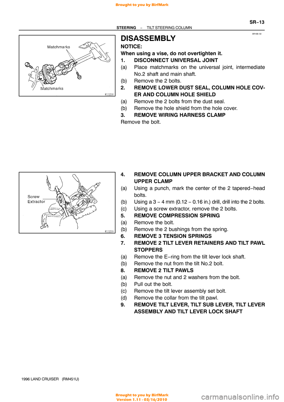
1. DISCONNECT UNIVERSAL JOINT
(a) Place matchmarks on the universal joint, intermediate
No.2 shaft and main shaft.
(b) Remove the 2 bolts.
2. REMOVE LOWER DUST SEAL, COLUMN HOLE COV-
ER AND COLUMN HOLE SHIELD
(a) Remove the 2 bolts from the dust seal.
(b) Remove the hole shield from the hole cover.
3. REMOVE WIRING HARNESS CLAMP
Remove the bolt.
4. REMOVE COLUMN UPPER BRACKET AND COLUMN UPPER CLAMP
(a) Using a punch, mark the center of the 2 tapered−head bolts.
(b) Using a 3 − 4 mm (0.12 − 0.16 in.) drill, drill into the 2 bolts.
(c) Using a screw extractor, remove the 2 bolts.
5. REMOVE COMPRESSION SPRING
(a) Remove the bolt.
(b) Remove the 2 bushings from the spring.
6. REMOVE 3 TENSION SPRINGS
7. REMOVE 2 TILT LEVER RETAINERS AND TILT PAWL STOPPERS
(a) Remove the E−ring from the tilt lever lock shaft.
(b) Remove the nut from the tilt No.2 bolt.
8. REMOVE 2 TILT PAWLS
(a) Remove the nut and 2 washers from the bolt.
(b) Pull out the bolt.
(c) Remove the tilt lever assembly set bolt.
(d) Remove the collar from the tilt pawl.
9. REMOVE TILT LEVER, TILT SUB LEVER, TILT LEVER ASSEMBLY AND TILT LEVER LOCK SHAFT
Brought to you by BirfMark
Brought to you by BirfMark
Version 1.11 - 03/16/2010
Page 1265 of 1399
R09496
SSTSST
SR−14
−
STEERING TILT STEERING COLUMN
1996 LAND CRUISER (RM451U)
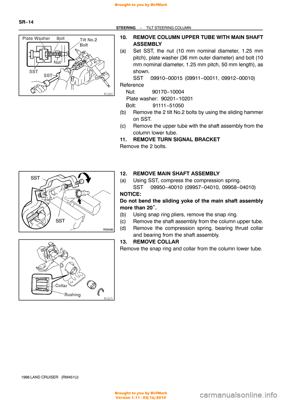
10. REMOVE COLUMN UPPER TUBE WITH MAIN SHAFT
ASSEMBLY
(a) Set SST, the nut (10 mm nominal diameter, 1.25 mm
pitch), plate washer (36 mm outer diameter) and bolt (10
mm nominal diameter, 1.25 mm pitch, 50 mm length), as
shown.
SST 09910−00015 (09911 −00011, 09912−00010)
Reference
Nut: 90170 −10004
Plate washer: 90201−10201
Bolt: 91111 −51050
(b) Remove the 2 tilt No.2 bolts by using the sliding hammer
on SST.
(c) Remove the upper tube with the shaft assembly from the column lower tube.
11. REMOVE TURN SIGNAL BRACKET
Remove the 2 bolts.
12. REMOVE MAIN SHAFT ASSEMBLY
(a) Using SST, compress the compression spring.
SST 09950−40010 (09957 −04010, 09958−04010)
NOTICE:
Do not bend the sliding yoke of the main shaft assembly
more than 20° .
(b) Using snap ring pliers, remove the snap ring.
(c) Remove the shaft assembly from the column upper tube.
(d) Remove the compression spring, bearing thrust collar
and bearing from the shaft assembly.
13. REMOVE COLLAR
Remove the snap ring and collar from the column lower tube.
Brought to you by BirfMark
Brought to you by BirfMark
Version 1.11 - 03/16/2010
Page 1268 of 1399
SR3128
Mark
”A”
”A”
−
STEERING TILT STEERING COLUMN
SR−17
1996 LAND CRUISER (RM451U)
7. INSTALL 2 TILT PAWLS
(a) Coat the collar with molybdenum disulfide lithium base
grease and install it to the tilt pawl.
(b) Install the pawl.
HINT:
Install the pawl pin into the long hole of the tilt lever/ tilt sub lever.
(c) Install the bolt through the pawls and tilt lever assembly.
(d) Temporarily install the 2 washers and nut.
(e) Torque the tilt lever assembly set bolt.
Torque: 2.9 N·m (30 kgf·cm, 26 in.·lbf)
8. ENGAGE AND ADJUST 2 TILT PAWLS
(a) Engage the tilt sub lever side pawl to the center of the ratchet.
(b) While turning the tilt lever side tilt pawl collar, completely engage the tilt lever side pawl to the ratchet.
(c) Torque the nut.
Torque: 5.9 N·m (60 kgf·cm, 52 in.·lbf)
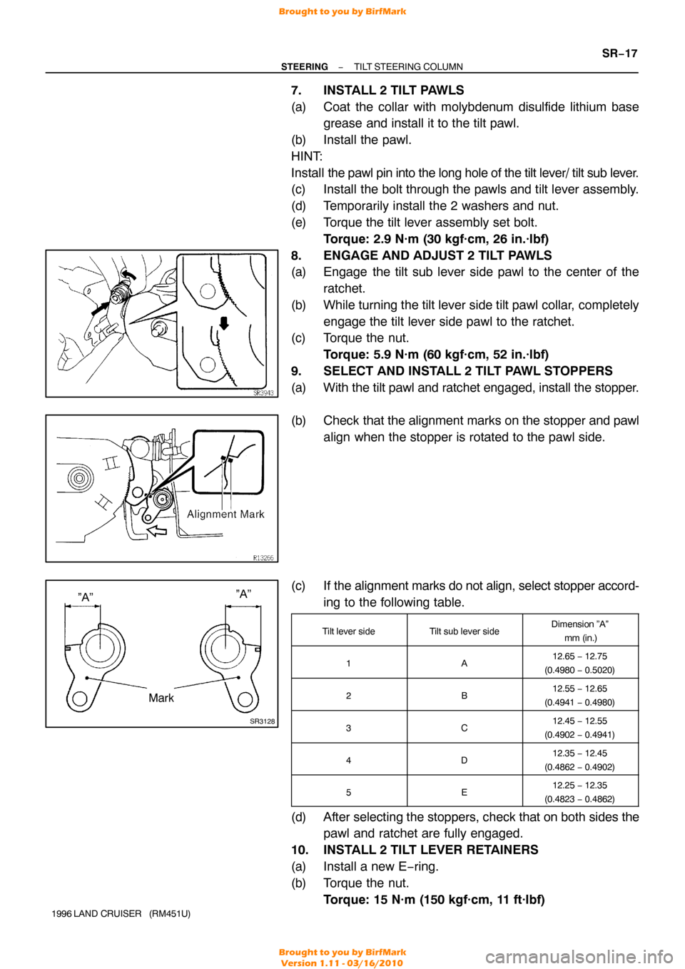
9. SELECT AND INSTALL 2 TILT PAWL STOPPERS
(a) With the tilt pawl and ratchet engaged, install the stopper.
(b) Check that the alignment marks on the stopper and pawl
align when the stopper is rotated to the pawl side.
(c) If the alignment marks do not align, select stopper accord-
ing to the following table.
Tilt lever sideTilt sub lever sideDimension ”A”
mm (in.)
1A12.65 − 12.75
(0.4980 − 0.5020)
2B12.55 − 12.65
(0.4941 − 0.4980)
3C12.45 − 12.55
(0.4902 − 0.4941)
4D12.35 − 12.45
(0.4862 − 0.4902)
5E12.25 − 12.35
(0.4823 − 0.4862)
(d) After selecting the stoppers, check that on both sides the
pawl and ratchet are fully engaged.
10. INSTALL 2 TILT LEVER RETAINERS
(a) Install a new E−ring.
(b) Torque the nut. Torque: 15 N·m (150 kgf·cm, 11 ft·lbf)
Brought to you by BirfMark
Brought to you by BirfMark
Version 1.11 - 03/16/2010
Page 1275 of 1399
SR16H−01
R08084
R08066
Soft Jaws
R13187
Press
SST
SST
R08067
Screwdriver
SR−24
−
STEERING POWER STEERING VANE PUMP
1996 LAND CRUISER (RM451U)
DISASSEMBLY
NOTICE:
When using a vise, do not overtighten it.
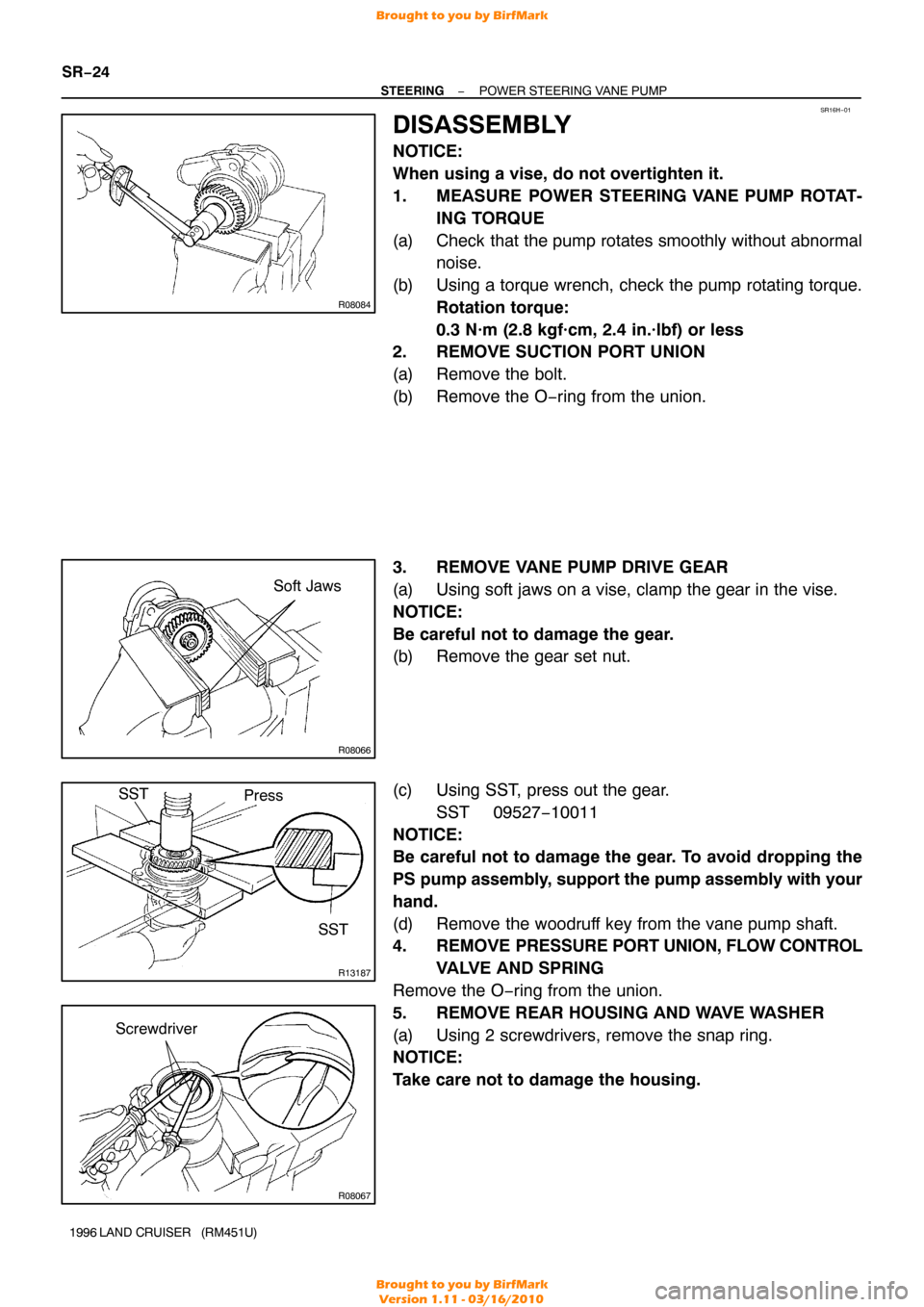
1. MEASURE POWER STEERING VANE PUMP ROTAT-
ING TORQUE
(a) Check that the pump rotates smoothly without abnormal noise.
(b) Using a torque wrench, check the pump rotating torque. Rotation torque:
0.3 N·m (2.8 kgf·cm, 2.4 in.·lbf) or less
2. REMOVE SUCTION PORT UNION
(a) Remove the bolt.
(b) Remove the O−ring from the union.
3. REMOVE VANE PUMP DRIVE GEAR
(a) Using soft jaws on a vise, clamp the gear in the vise.
NOTICE:
Be careful not to damage the gear.
(b) Remove the gear set nut.
(c) Using SST, press out the gear.
SST 09527−10011
NOTICE:
Be careful not to damage the gear. To avoid dropping the
PS pump assembly, support the pump assembly with your
hand.
(d) Remove the woodruff key from the vane pump shaft.
4. REMOVE PRESSURE PORT UNION, FLOW CONTROL
VALVE AND SPRING
Remove the O−ring from the union.
5. REMOVE REAR HOUSING AND WAVE WASHER
(a) Using 2 screwdrivers, remove the snap ring.
NOTICE:
Take care not to damage the housing.
Brought to you by BirfMark
Brought to you by BirfMark
Version 1.11 - 03/16/2010
Page 1276 of 1399
R11234
Rear Housing
Brass Bar
R11235
Rear Housing Wood Block
R08075
Extension Bar
R08074
−
STEERING POWER STEERING VANE PUMP
SR−25
1996 LAND CRUISER (RM451U)
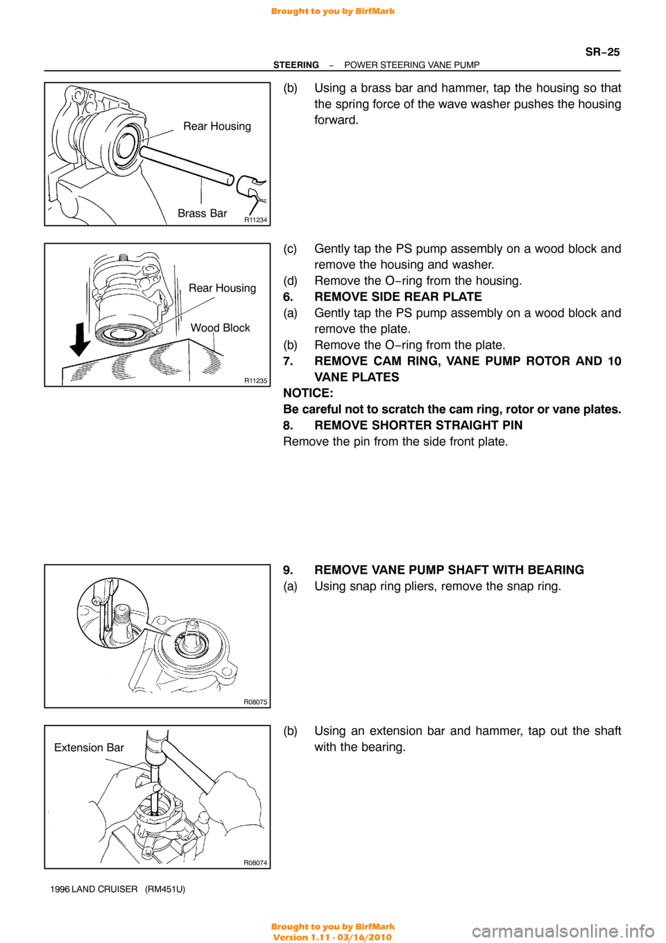
(b) Using a brass bar and hammer, tap the housing so that
the spring force of the wave washer pushes the housing
forward.
(c) Gently tap the PS pump assembly on a wood block and remove the housing and washer.
(d) Remove the O−ring from the housing.
6. REMOVE SIDE REAR PLATE
(a) Gently tap the PS pump assembly on a wood block and remove the plate.
(b) Remove the O−ring from the plate.
7. REMOVE CAM RING, VANE PUMP ROTOR AND 10 VANE PLATES
NOTICE:
Be careful not to scratch the cam ring, rotor or vane plates.
8. REMOVE SHORTER STRAIGHT PIN
Remove the pin from the side front plate.
9. REMOVE VANE PUMP SHAFT WITH BEARING
(a) Using snap ring pliers, remove the snap ring.
(b) Using an extension bar and hammer, tap out the shaft
with the bearing.
Brought to you by BirfMark
Brought to you by BirfMark
Version 1.11 - 03/16/2010
Page 1284 of 1399
R08069
R08082
R08066
Soft Jaws
−
STEERING POWER STEERING VANE PUMP
SR−31
1996 LAND CRUISER (RM451U)
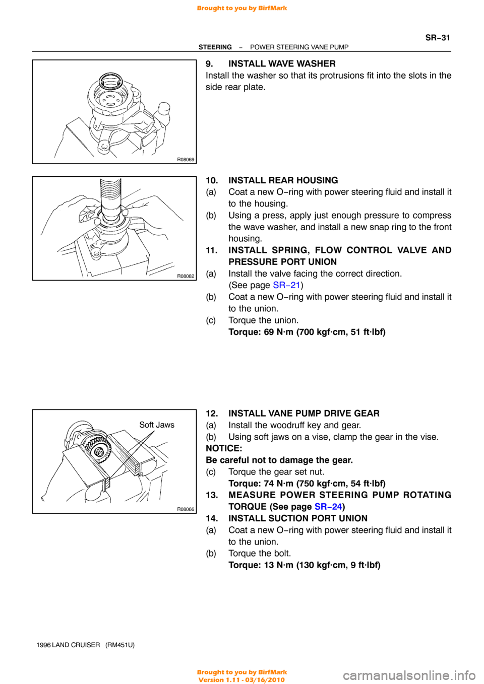
9. INSTALL WAVE WASHER
Install the washer so that its protrusions fit into the slots in the
side rear plate.
10. INSTALL REAR HOUSING
(a) Coat a new O−ring with power steering fluid and install it
to the housing.
(b) Using a press, apply just enough pressure to compress the wave washer, and install a new snap ring to the front
housing.
11. INSTALL SPRING, FLOW CONTROL VALVE AND PRESSURE PORT UNION
(a) Install the valve facing the correct direction. (See page SR−21 )
(b) Coat a new O −ring with power steering fluid and install it
to the union.
(c) Torque the union. Torque: 69 N·m (700 kgf·cm, 51 ft·lbf)
12. INSTALL VANE PUMP DRIVE GEAR
(a) Install the woodruff key and gear.
(b) Using soft jaws on a vise, clamp the gear in the vise.
NOTICE:
Be careful not to damage the gear.
(c) Torque the gear set nut. Torque: 74 N·m (750 kgf·cm, 54 ft·lbf)
13. MEASURE POWER STEERING PUMP ROTATING
TORQUE (See page SR−24 )
14. INSTALL SUCTION PORT UNION
(a) Coat a new O −ring with power steering fluid and install it
to the union.
(b) Torque the bolt.
Torque: 13 N·m (130 kgf·cm, 9 ft·lbf)
Brought to you by BirfMark
Brought to you by BirfMark
Version 1.11 - 03/16/2010