Page 1161 of 1399
Z15220
FIPG Width Approx.
1 − 2 mm (0.04 − 0.08 in.)
SA2129
Z10150
Adhesive
SA−98
−
SUSPENSION AND AXLE REAR DIFFERENTIAL CARRIER
1996 LAND CRUISER (RM451U)
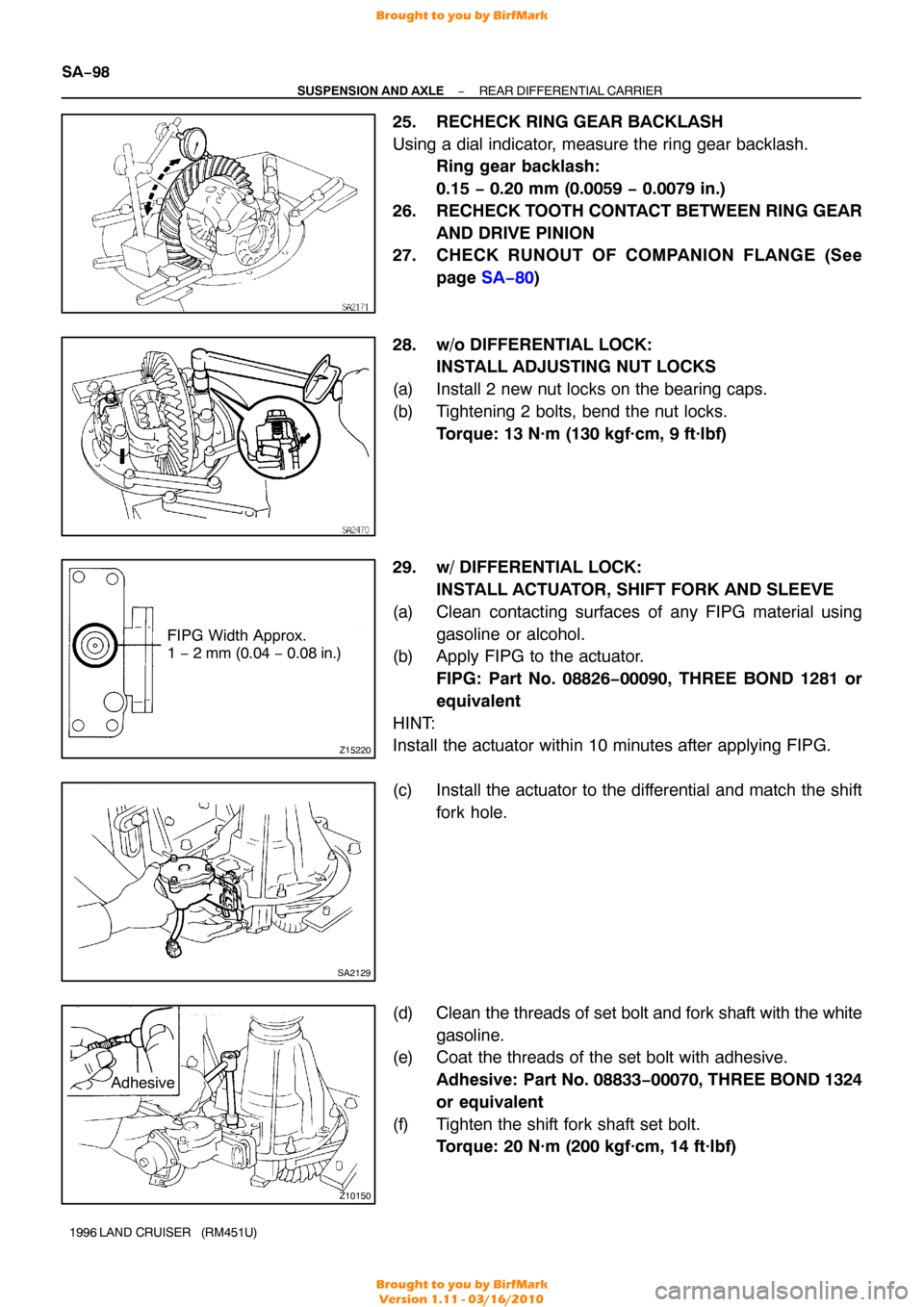
25. RECHECK RING GEAR BACKLASH
Using a dial indicator, measure the ring gear backlash.
Ring gear backlash:
0.15 − 0.20 mm (0.0059 − 0.0079 in.)
26. RECHECK TOOTH CONTACT BETWEEN RING GEAR AND DRIVE PINION
27. CHECK RUNOUT OF COMPANION FLANGE (See
page SA−80 )
28. w/o DIFFERENTIAL LOCK: INSTALL ADJUSTING NUT LOCKS
(a) Install 2 new nut locks on the bearing caps.
(b) Tightening 2 bolts, bend the nut locks. Torque: 13 N·m (130 kgf·cm, 9 ft·lbf)
29. w/ DIFFERENTIAL LOCK: INSTALL ACTUATOR, SHIFT FORK AND SLEEVE
(a) Clean contacting surfaces of any FIPG material using gasoline or alcohol.
(b) Apply FIPG to the actuator.
FIPG: Part No. 08826−00090, THREE BOND 1281 or
equivalent
HINT:
Install the actuator within 10 minutes after applying FIPG.
(c) Install the actuator to the differential and match the shift fork hole.
(d) Clean the threads of set bolt and fork shaft with the white
gasoline.
(e) Coat the threads of the set bolt with adhesive.
Adhesive: Part No. 08833 −00070, THREE BOND 1324
or equivalent
(f) Tighten the shift fork shaft set bolt. Torque: 20 N·m (200 kgf·cm, 14 ft·lbf)
Brought to you by BirfMark
Brought to you by BirfMark
Version 1.11 - 03/16/2010
Page 1255 of 1399
SR165−01
SR−2
−
STEERING TROUBLESHOOTING
1053
Author�: Date�:
1996 LAND CRUISER (RM451U)
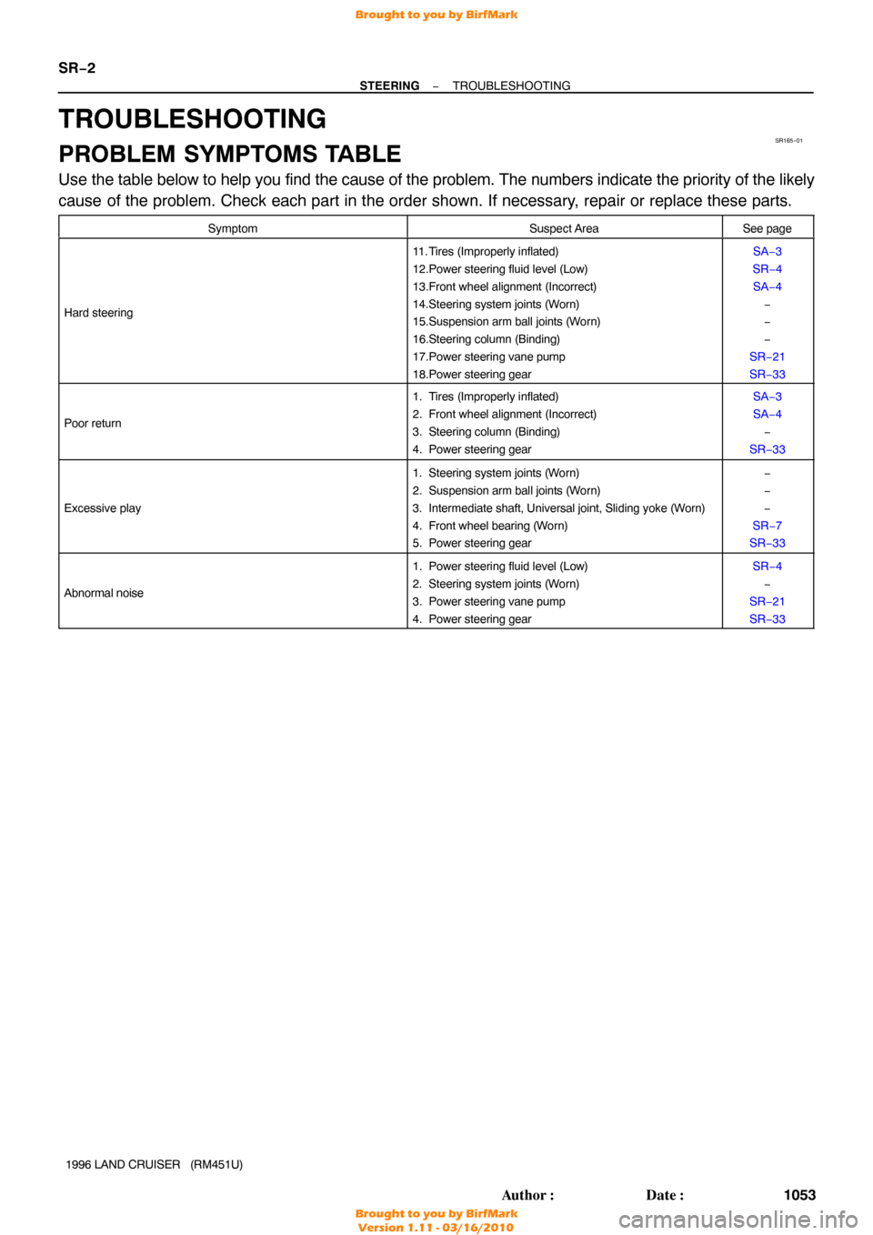
TROUBLESHOOTING
PROBLEM SYMPTOMS TABLE
Use the table below to help you find the cause of the problem. The numbers \
indicate the priority of the likely
cause of the problem. Check each part in the order shown. If necessary, repair or replace these parts.
SymptomSuspect AreaSee page
Hard steering
11. Tires (Improperly inflated)
12.Power steering fluid level (Low)
13.Front wheel alignment (Incorrect)
14.Steering system joints (Worn)
15.Suspension arm ball joints (W orn)
16.Steering column (Binding)
17.Power steering vane pump
18.Power steering gearSA−3
SR−4 SA−4 −
−
−
SR−21
SR−33
Poor return
1. Tires (Improperly inflated)
2. Front wheel alignment (Incorrect)
3. Steering column (Binding)
4. Power steering gearSA−3
SA−4 −
SR−33
Excessive play
1. Steering system joints (Worn)
2. Suspension arm ball joints (W orn)
3. Intermediate shaft, Universal joint, Sliding yoke (Worn)
4. Front wheel bearing (W orn)
5. Power steering gear−
−
−
SR−7
SR−33
Abnormal noise
1. Power steering fluid level (Low)
2. Steering system joints (Worn)
3. Power steering vane pump
4. Power steering gearSR−4 −
SR−21
SR−33
Brought to you by BirfMark
Brought to you by BirfMark
Version 1.11 - 03/16/2010
Page 1265 of 1399
R09496
SSTSST
SR−14
−
STEERING TILT STEERING COLUMN
1996 LAND CRUISER (RM451U)
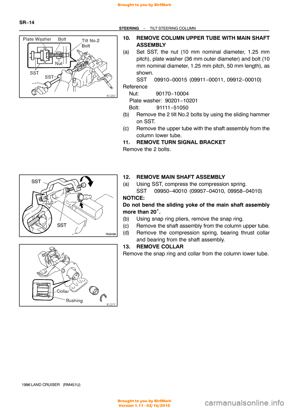
10. REMOVE COLUMN UPPER TUBE WITH MAIN SHAFT
ASSEMBLY
(a) Set SST, the nut (10 mm nominal diameter, 1.25 mm
pitch), plate washer (36 mm outer diameter) and bolt (10
mm nominal diameter, 1.25 mm pitch, 50 mm length), as
shown.
SST 09910−00015 (09911 −00011, 09912−00010)
Reference
Nut: 90170 −10004
Plate washer: 90201−10201
Bolt: 91111 −51050
(b) Remove the 2 tilt No.2 bolts by using the sliding hammer
on SST.
(c) Remove the upper tube with the shaft assembly from the column lower tube.
11. REMOVE TURN SIGNAL BRACKET
Remove the 2 bolts.
12. REMOVE MAIN SHAFT ASSEMBLY
(a) Using SST, compress the compression spring.
SST 09950−40010 (09957 −04010, 09958−04010)
NOTICE:
Do not bend the sliding yoke of the main shaft assembly
more than 20° .
(b) Using snap ring pliers, remove the snap ring.
(c) Remove the shaft assembly from the column upper tube.
(d) Remove the compression spring, bearing thrust collar
and bearing from the shaft assembly.
13. REMOVE COLLAR
Remove the snap ring and collar from the column lower tube.
Brought to you by BirfMark
Brought to you by BirfMark
Version 1.11 - 03/16/2010
Page 1267 of 1399
SR16D−02
R09496
SST
SR−16
−
STEERING TILT STEERING COLUMN
1996 LAND CRUISER (RM451U)
REASSEMBLY
NOTICE:
When using a vise, do not overtighten it.
1. COAT WITH MOLYBDENUM DISULFIDE LITHIUM BASE GREASE (See page SR−9 )
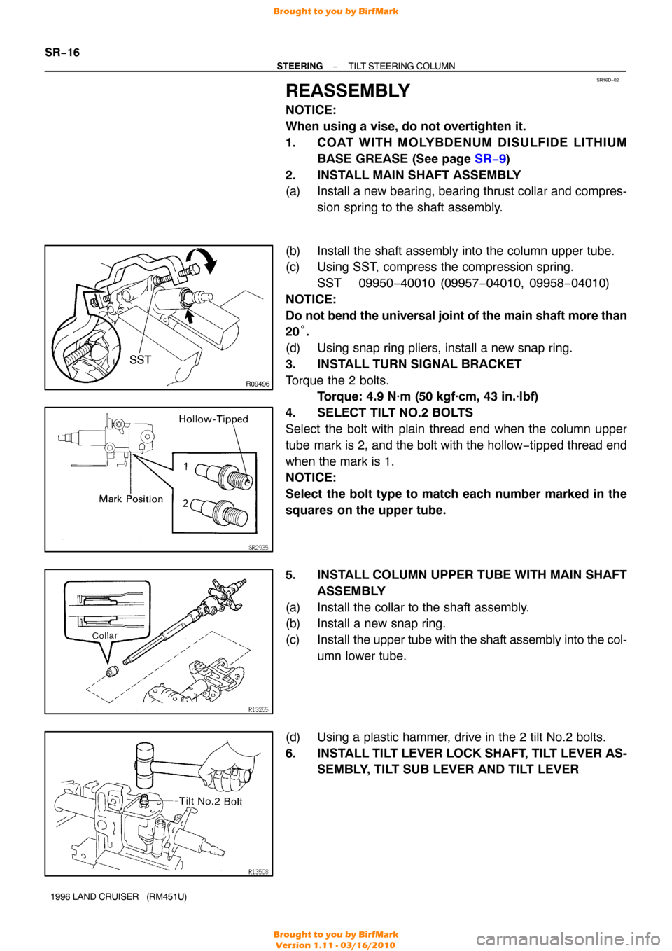
2. INSTALL MAIN SHAFT ASSEMBLY
(a) Install a new bearing, bearing thrust collar and compres- sion spring to the shaft assembly.
(b) Install the shaft assembly into the column upper tube.
(c) Using SST, compress the compression spring. SST 09950−40010 (09957 −04010, 09958−04010)
NOTICE:
Do not bend the universal joint of the main shaft more than
20 °.
(d) Using snap ring pliers, install a new snap ring.
3. INSTALL TURN SIGNAL BRACKET
Torque the 2 bolts. Torque: 4.9 N·m (50 kgf·cm, 43 in.·lbf)
4. SELECT TILT NO.2 BOLTS
Select the bolt with plain thread end when the column upper
tube mark is 2, and the bolt with the hollow −tipped thread end
when the mark is 1.
NOTICE:
Select the bolt type to match each number marked in the
squares on the upper tube.
5. INSTALL COLUMN UPPER TUBE WITH MAIN SHAFT ASSEMBLY
(a) Install the collar to the shaft assembly.
(b) Install a new snap ring.
(c) Install the upper tube with the shaft assembly into the col-
umn lower tube.
(d) Using a plastic hammer, drive in the 2 tilt No.2 bolts.
6. INSTALL TILT LEVER LOCK SHAFT, TILT LEVER AS- SEMBLY, TILT SUB LEVER AND TILT LEVER
Brought to you by BirfMark
Brought to you by BirfMark
Version 1.11 - 03/16/2010
Page 1276 of 1399
R11234
Rear Housing
Brass Bar
R11235
Rear Housing Wood Block
R08075
Extension Bar
R08074
−
STEERING POWER STEERING VANE PUMP
SR−25
1996 LAND CRUISER (RM451U)
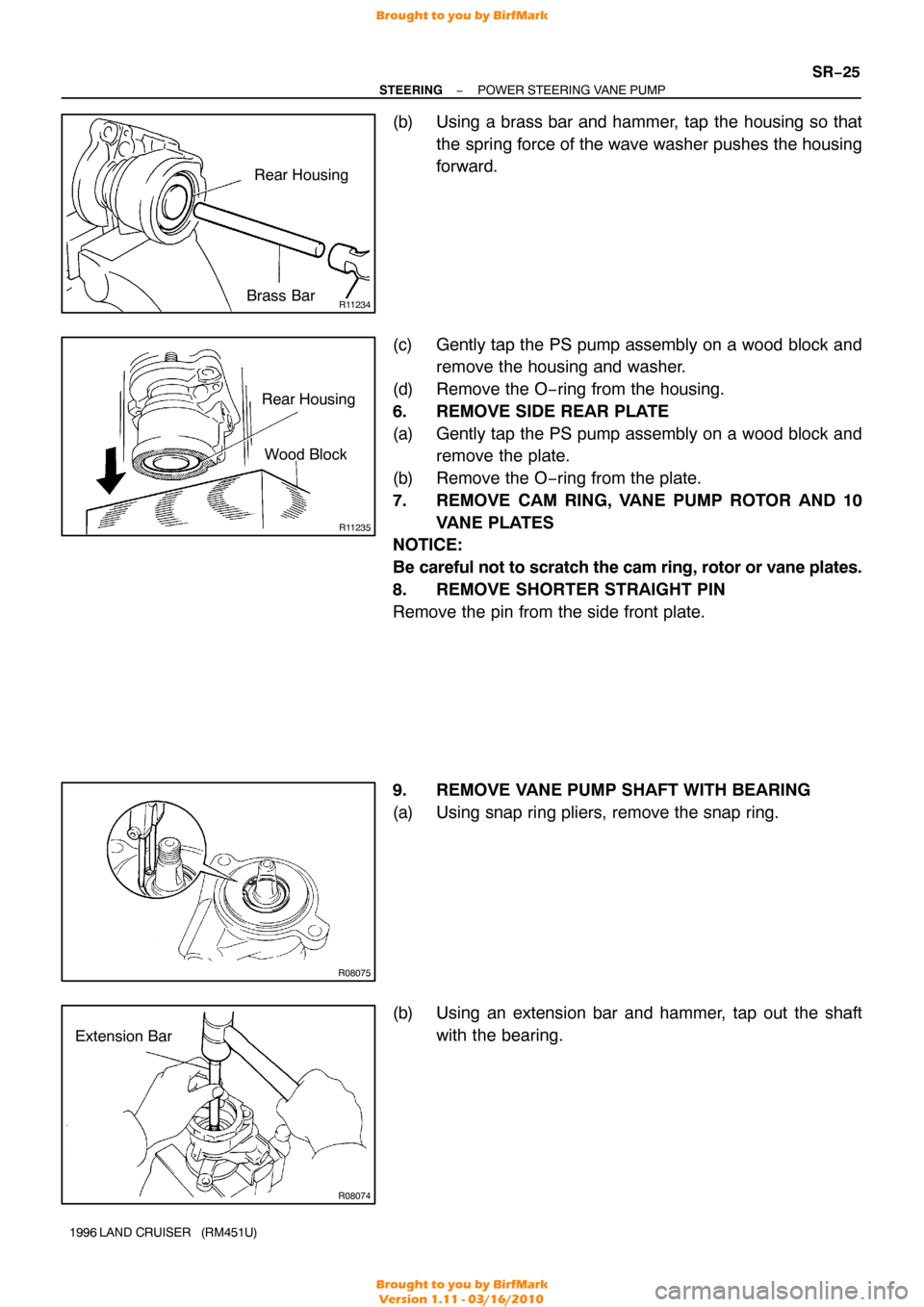
(b) Using a brass bar and hammer, tap the housing so that
the spring force of the wave washer pushes the housing
forward.
(c) Gently tap the PS pump assembly on a wood block and remove the housing and washer.
(d) Remove the O−ring from the housing.
6. REMOVE SIDE REAR PLATE
(a) Gently tap the PS pump assembly on a wood block and remove the plate.
(b) Remove the O−ring from the plate.
7. REMOVE CAM RING, VANE PUMP ROTOR AND 10 VANE PLATES
NOTICE:
Be careful not to scratch the cam ring, rotor or vane plates.
8. REMOVE SHORTER STRAIGHT PIN
Remove the pin from the side front plate.
9. REMOVE VANE PUMP SHAFT WITH BEARING
(a) Using snap ring pliers, remove the snap ring.
(b) Using an extension bar and hammer, tap out the shaft
with the bearing.
Brought to you by BirfMark
Brought to you by BirfMark
Version 1.11 - 03/16/2010
Page 1280 of 1399
SR4528
Tape
Screwdriver
R13761REMOVEINSTALL
Press
Bearing
R08077
Press
SST Oil Seal
W03071
Socket
Wrench
Press
A
A 3.4 mm
(+ 3mm)
−
STEERING POWER STEERING VANE PUMP
SR−29
1996 LAND CRUISER (RM451U)
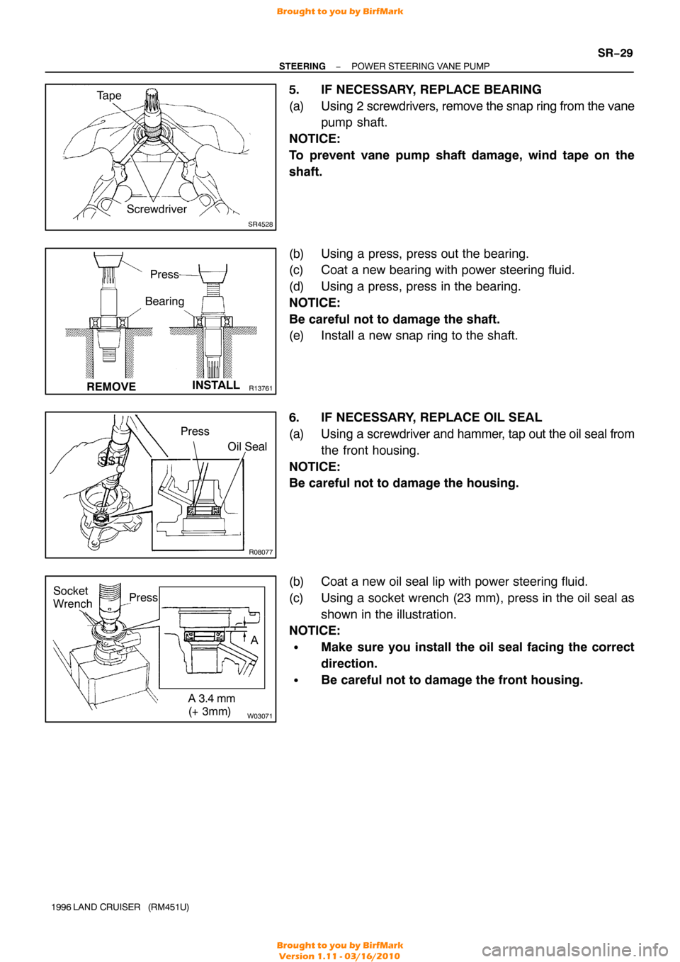
5. IF NECESSARY, REPLACE BEARING
(a) Using 2 screwdrivers, remove the snap ring from the vane
pump shaft.
NOTICE:
To prevent vane pump shaft damage, wind tape on the
shaft.
(b) Using a press, press out the bearing.
(c) Coat a new bearing with power steering fluid.
(d) Using a press, press in the bearing.
NOTICE:
Be careful not to damage the shaft.
(e) Install a new snap ring to the shaft.
6. IF NECESSARY, REPLACE OIL SEAL
(a) Using a screwdriver and hammer, tap out the oil seal from
the front housing.
NOTICE:
Be careful not to damage the housing.
(b) Coat a new oil seal lip with power steering fluid.
(c) Using a socket wrench (23 mm), press in the oil seal as shown in the illustration.
NOTICE:
�Make sure you install the oil seal facing the correct
direction.
�Be careful not to damage the front housing.
Brought to you by BirfMark
Brought to you by BirfMark
Version 1.11 - 03/16/2010
Page 1283 of 1399
SR16J−01
R08080
Socket
WrenchPress
R08098
Inscribed Mark
R08081
Round End
SR−30
−
STEERING POWER STEERING VANE PUMP
1996 LAND CRUISER (RM451U)
REASSEMBLY
NOTICE:
When using a vise, do not overtighten it.
1. COAT WITH POWER STEERING FLUID
(See page SR−21 )
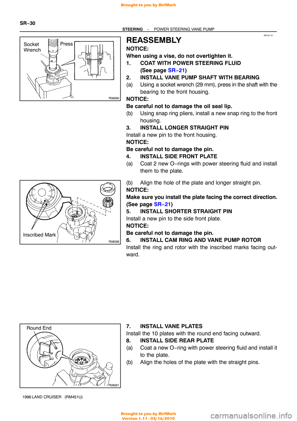
2. INSTALL VANE PUMP SHAFT WITH BEARING
(a) Using a socket wrench (29 mm), press in the shaft with the bearing to the front housing.
NOTICE:
Be careful not to damage the oil seal lip.
(b) Using snap ring pliers, install a new snap ring to the front housing.
3. INSTALL LONGER STRAIGHT PIN
Install a new pin to the front housing.
NOTICE:
Be careful not to damage the pin.
4. INSTALL SIDE FRONT PLATE
(a) Coat 2 new O−rings with power steering fluid and install them to the plate.
(b) Align the hole of the plate and longer straight pin.
NOTICE:
Make sure you install the plate facing the correct direction.
(See page SR−21 )
5. INSTALL SHORTER STRAIGHT PIN
Install a new pin to the side front plate.
NOTICE:
Be careful not to damage the pin.
6. INSTALL CAM RING AND VANE PUMP ROTOR
Install the ring and rotor with the inscribed marks facing out-
ward.
7. INSTALL VANE PLATES
Install the 10 plates with the round end facing outward.
8. INSTALL SIDE REAR PLATE
(a) Coat a new O −ring with power steering fluid and install it
to the plate.
(b) Align the holes of the plate with the straight pins.
Brought to you by BirfMark
Brought to you by BirfMark
Version 1.11 - 03/16/2010
Page 1306 of 1399
−
SERVICE SPECIFICATIONS ENGINE MECHANICAL
SS−5
128
Author�: Date�:
1996 LAND CRUISER (RM451U)
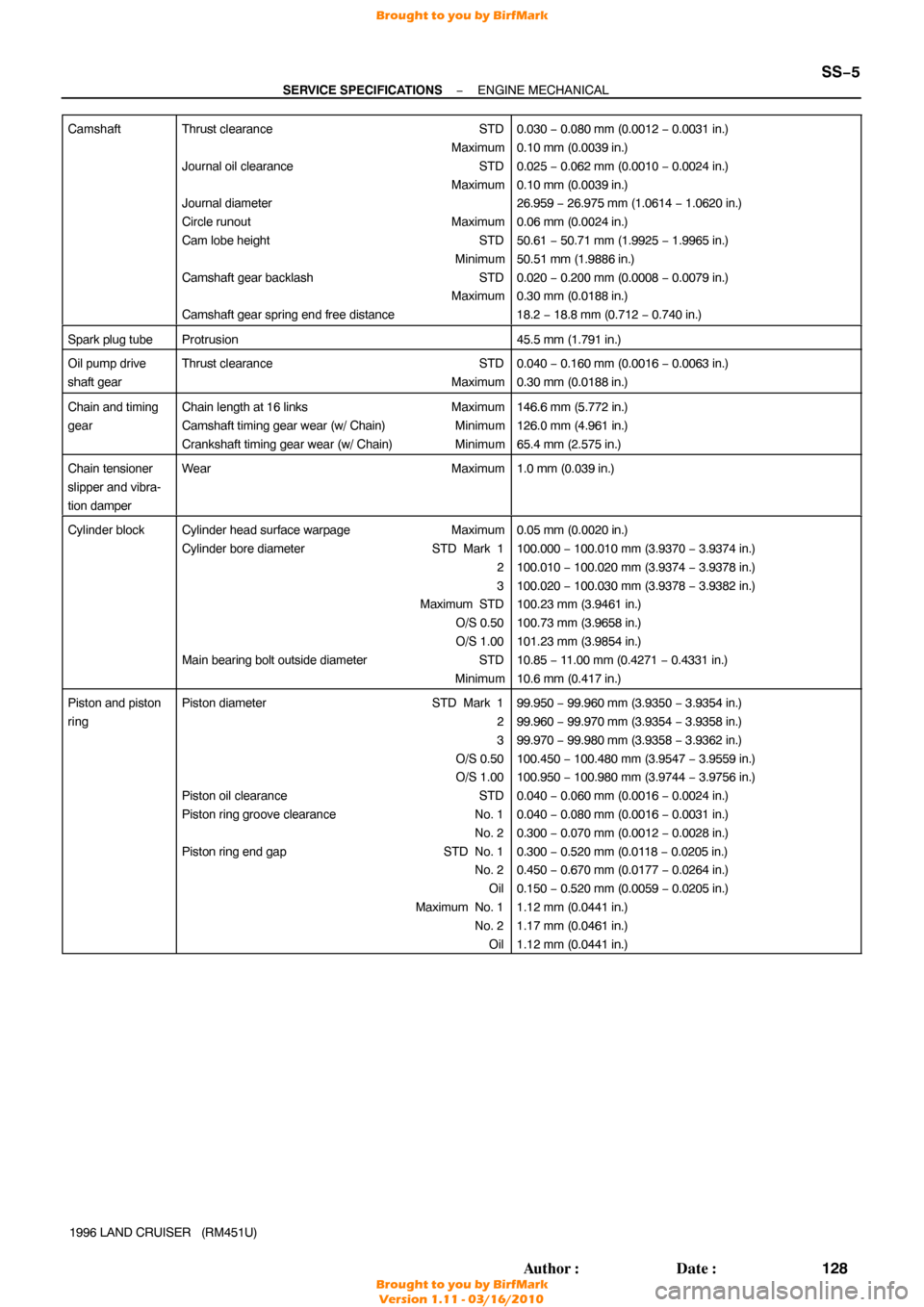
Camshaft
Thrust clearance
STD
Maximum
Journal oil clearance STD
Maximum
Journal diameter
Circle runout Maximum
Cam lobe height STD
Minimum
Camshaft gear backlash STD
Maximum
Camshaft gear spring end free distance0.030 − 0.080 mm (0.0012 − 0.0031 in.)
0.10 mm (0.0039 in.)
0.025 − 0.062 mm (0.0010 − 0.0024 in.)
0.10 mm (0.0039 in.)
26.959 − 26.975 mm (1.0614 − 1.0620 in.)
0.06 mm (0.0024 in.)
50.61 − 50.71 mm (1.9925 − 1.9965 in.)
50.51 mm (1.9886 in.)
0.020 − 0.200 mm (0.0008 − 0.0079 in.)
0.30 mm (0.0188 in.)
18.2 − 18.8 mm (0.712 − 0.740 in.)
Spark plug tubeProtrusion45.5 mm (1.791 in.)
Oil pump drive
shaft gearThrust clearance STD
Maximum0.040 − 0.160 mm (0.0016 − 0.0063 in.)
0.30 mm (0.0188 in.)
Chain and timing
gearChain length at 16 links Maximum
Camshaft timing gear wear (w/ Chain) Minimum
Crankshaft timing gear wear (w/ Chain) Minimum146.6 mm (5.772 in.)
126.0 mm (4.961 in.)
65.4 mm (2.575 in.)
Chain tensioner
slipper and vibra-
tion damperWearMaximum1.0 mm (0.039 in.)
Cylinder blockCylinder head surface warpageMaximum
Cylinder bore diameter STD Mark 1
2
3
Maximum STD
O/S 0.50
O/S 1.00
Main bearing bolt outside diameter STD
Minimum0.05 mm (0.0020 in.)
100.000 − 100.010 mm (3.9370 − 3.9374 in.)
100.010 − 100.020 mm (3.9374 − 3.9378 in.)
100.020 − 100.030 mm (3.9378 − 3.9382 in.)
100.23 mm (3.9461 in.)
100.73 mm (3.9658 in.)
101.23 mm (3.9854 in.)
10.85 − 11.00 mm (0.4271 − 0.4331 in.)
10.6 mm (0.417 in.)
Piston and piston
ringPiston diameter STD Mark 1
2
3
O/S 0.50
O/S 1.00
Piston oil clearance STD
Piston ring groove clearance No. 1
No. 2
Piston ring end gap STD No. 1
No. 2
Oil
Maximum No. 1 No. 2Oil99.950 − 99.960 mm (3.9350 − 3.9354 in.)
99.960 − 99.970 mm (3.9354 − 3.9358 in.)
99.970 − 99.980 mm (3.9358 − 3.9362 in.)
100.450 − 100.480 mm (3.9547 − 3.9559 in.)
100.950 − 100.980 mm (3.9744 − 3.9756 in.)
0.040 − 0.060 mm (0.0016 − 0.0024 in.)
0.040 − 0.080 mm (0.0016 − 0.0031 in.)
0.300 − 0.070 mm (0.0012 − 0.0028 in.)
0.300 − 0.520 mm (0.0118 − 0.0205 in.)
0.450 − 0.670 mm (0.0177 − 0.0264 in.)
0.150 − 0.520 mm (0.0059 − 0.0205 in.)
1.12 mm (0.0441 in.)
1.17 mm (0.0461 in.)
1.12 mm (0.0441 in.)
Brought to you by BirfMark
Brought to you by BirfMark
Version 1.11 - 03/16/2010