Page 1103 of 1399
SA2401
SST
SA2403
SA2161
MP Grease
Z10100
SA−40
−
SUSPENSION AND AXLE FRONT DIFFERENTIAL CARRIER
1996 LAND CRUISER (RM451U)
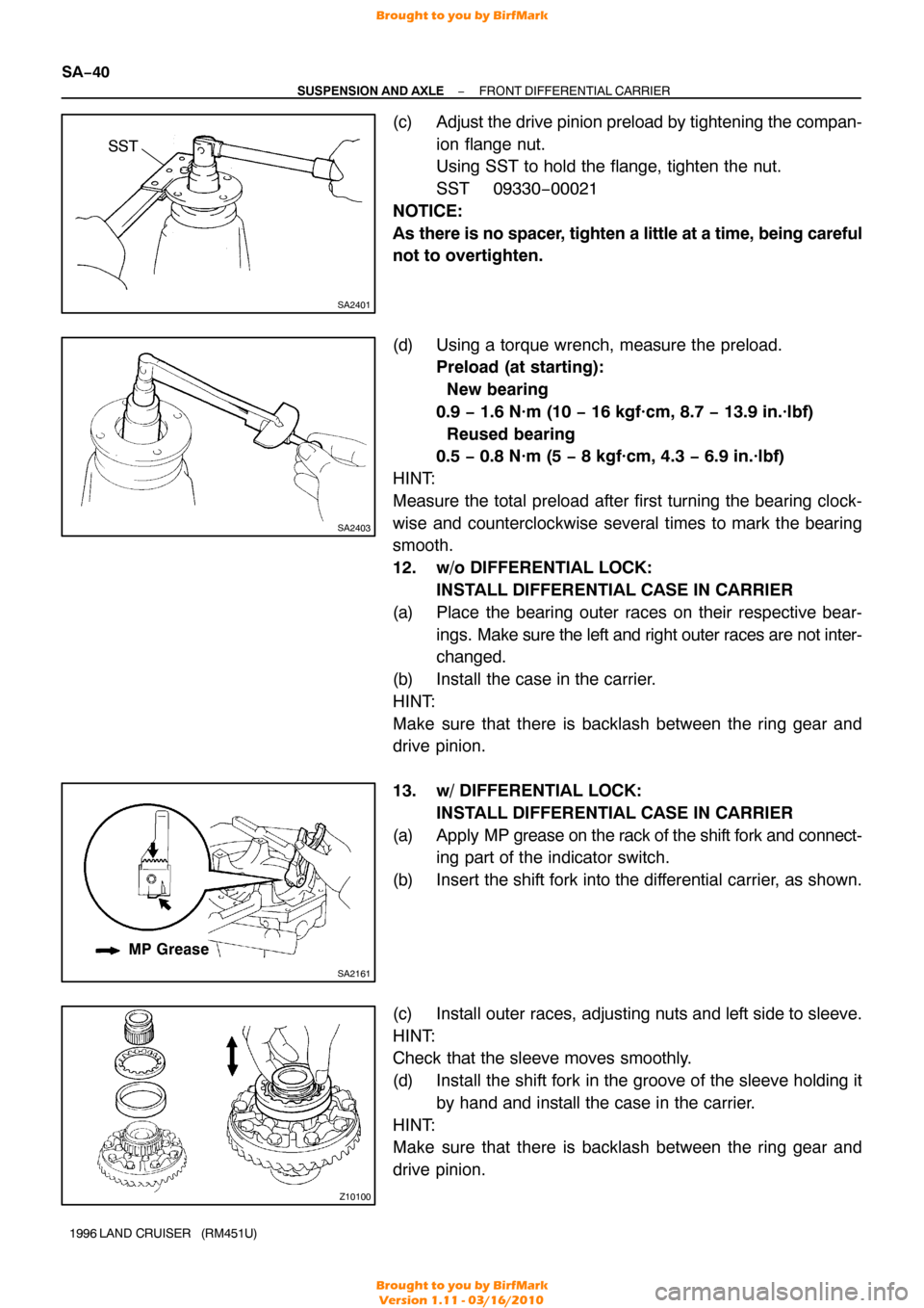
(c) Adjust the drive pinion preload by tightening the compan-
ion flange nut.
Using SST to hold the flange, tighten the nut.
SST 09330−00021
NOTICE:
As there is no spacer, tighten a little at a time, being careful
not to overtighten.
(d) Using a torque wrench, measure the preload. Preload (at starting):
New bearing
0.9 − 1.6 N·m (10 − 16 kgf·cm, 8.7 − 13.9 in.·lbf)
Reused bearing
0.5 − 0.8 N·m (5 − 8 kgf·cm, 4.3 − 6.9 in.·lbf)
HINT:
Measure the total preload after first turning the bearing clock-
wise and counterclockwise several times to mark the bearing
smooth.
12. w/o DIFFERENTIAL LOCK: INSTALL DIFFERENTIAL CASE IN CARRIER
(a) Place the bearing outer races on their respective bear- ings. Make sure the left and right outer races are not inter-
changed.
(b) Install the case in the carrier.
HINT:
Make sure that there is backlash between the ring gear and
drive pinion.
13. w/ DIFFERENTIAL LOCK: INSTALL DIFFERENTIAL CASE IN CARRIER
(a) Apply MP grease on the rack of the shift fork and connect- ing part of the indicator switch.
(b) Insert the shift fork into the differential carrier, as shown.
(c) Install outer races, adjusting nuts and left side to sleeve.
HINT:
Check that the sleeve moves smoothly.
(d) Install the shift fork in the groove of the sleeve holding it by hand and install the case in the carrier.
HINT:
Make sure that there is backlash between the ring gear and
drive pinion.
Brought to you by BirfMark
Brought to you by BirfMark
Version 1.11 - 03/16/2010
Page 1104 of 1399
Z06898
SA2458
Matchmarks
SA2467SST
Z10281SST
SA2308
−
SUSPENSION AND AXLE FRONT DIFFERENTIAL CARRIER
SA−41
1996 LAND CRUISER (RM451U)
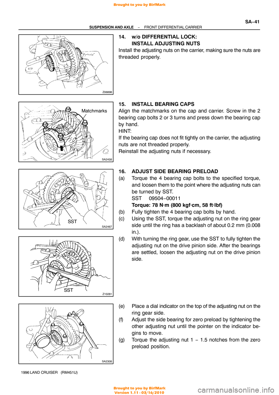
14. w/o DIFFERENTIAL LOCK:
INSTALL ADJUSTING NUTS
Install the adjusting nuts on the carrier , making sure the nuts are
threaded properly.
15. INSTALL BEARING CAPS
Align the matchmarks on the cap and carrier. Screw in the 2
bearing cap bolts 2 or 3 turns and press down the bearing cap
by hand.
HINT:
If the bearing cap does not fit tightly on the carrier , the adjusting
nuts are not threaded properly.
Reinstall the adjusting nuts if necessary.
16. ADJUST SIDE BEARING PRELOAD
(a) Torque the 4 bearing cap bolts to the specified torque, and loosen them to the point where the adjusting nuts can
be turned by SST.
SST 09504−00011
Torque: 78 N·m (800 kgf·cm, 58 ft·lbf)
(b) Fully tighten the 4 bearing cap bolts by hand.
(c) Using the SST, torque the adjusting nut on the ring gear side until the ring has a backlash of about 0.2 mm (0.008
in.).
(d) With turning the ring gear, use the SST to fully tighten the adjusting nut on the drive pinion side. After the bearings
are settled, loosen the adjusting nut on the drive pinion
side.
(e) Place a dial indicator on the top of the adjusting nut on the ring gear side.
(f) Adjust the side bearing for zero preload by tightening the
other adjusting nut until the pointer on the indicator be-
gins to move.
(g) Torque the adjusting nut 1 − 1.5 notches from the zero preload position.
Brought to you by BirfMark
Brought to you by BirfMark
Version 1.11 - 03/16/2010
Page 1105 of 1399
SA2443SST
SA2403
SA2463
FA2013
Proper ContactHeel Contact
Face Contact
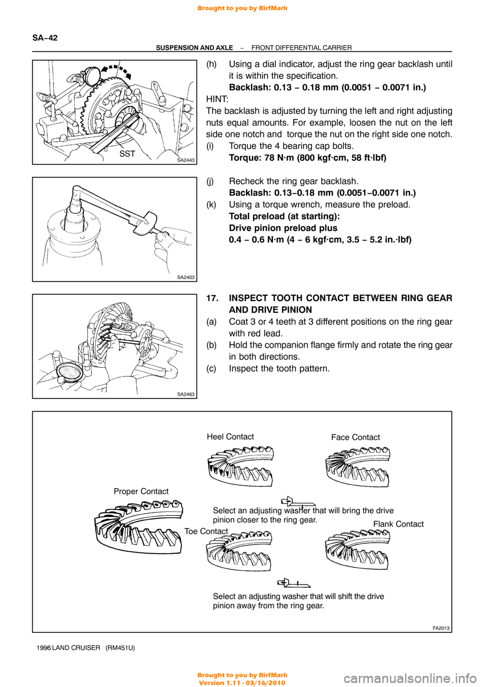
Select an adjusting washer that will bring the drive
pinion closer to the ring gear.
Select an adjusting washer that will shift the drive
pinion away from the ring gear.
Toe Contact
Flank Contact
SA−42
−
SUSPENSION AND AXLE FRONT DIFFERENTIAL CARRIER
1996 LAND CRUISER (RM451U)
(h) Using a dial indicator, adjust the ring gear backlash until
it is within the specification.
Backlash: 0.13 − 0.18 mm (0.0051 − 0.0071 in.)
HINT:
The backlash is adjusted by turning the left and right adjusting
nuts equal amounts. For example, loosen the nut on the left
side one notch and torque the nut on the right side one notch.
(i) Torque the 4 bearing cap bolts. Torque: 78 N·m (800 kgf·cm, 58 ft·lbf)
(j) Recheck the ring gear backlash. Backlash: 0.13 −0.18 mm (0.0051 −0.0071 in.)
(k) Using a torque wrench, measure the preload. Total preload (at starting):
Drive pinion preload plus
0.4 − 0.6 N·m (4 − 6 kgf·cm, 3.5 − 5.2 in.·lbf)
17. INSPECT TOOTH CONTACT BETWEEN RING GEAR AND DRIVE PINION
(a) Coat 3 or 4 teeth at 3 different positions on the ring gear with red lead.
(b) Hold the companion flange firmly and rotate the ring gear
in both directions.
(c) Inspect the tooth pattern.
Brought to you by BirfMark
Brought to you by BirfMark
Version 1.11 - 03/16/2010
Page 1106 of 1399
FA2041
Washer
W00529
SA2407
SST
R13140
SST
−
SUSPENSION AND AXLE FRONT DIFFERENTIAL CARRIER
SA−43
1996 LAND CRUISER (RM451U)
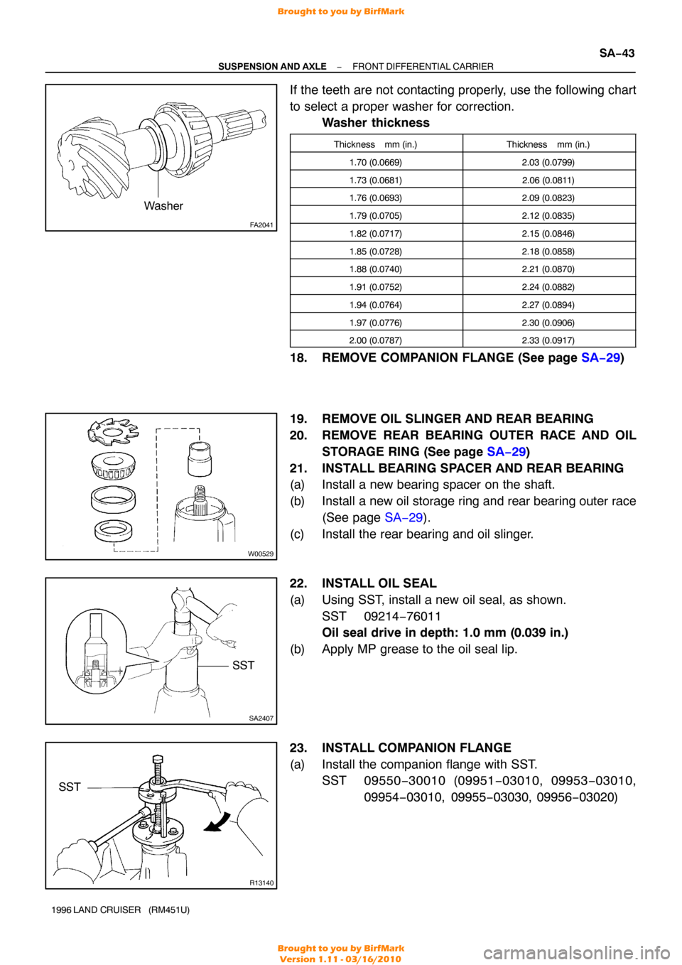
If the teeth are not contacting properly, use the following chart
to select a proper washer for correction.
Washer thickness
Thickness mm (in.)Thickness mm (in.)
1.70 (0.0669)2.03 (0.0799)
1.73 (0.0681)2.06 (0.0811)
1.76 (0.0693)2.09 (0.0823)
1.79 (0.0705)2.12 (0.0835)
1.82 (0.0717)2.15 (0.0846)
1.85 (0.0728)2.18 (0.0858)
1.88 (0.0740)2.21 (0.0870)
1.91 (0.0752)2.24 (0.0882)
1.94 (0.0764)2.27 (0.0894)
1.97 (0.0776)2.30 (0.0906)
2.00 (0.0787)2.33 (0.0917)
18. REMOVE COMPANION FLANGE (See page SA−29)
19. REMOVE OIL SLINGER AND REAR BEARING
20. REMOVE REAR BEARING OUTER RACE AND OIL STORAGE RING (See page SA−29 )
21. INSTALL BEARING SPACER AND REAR BEARING
(a) Install a new bearing spacer on the shaft.
(b) Install a new oil storage ring and rear bearing outer race (See page SA−29 ).
(c) Install the rear bearing and oil slinger.
22. INSTALL OIL SEAL
(a) Using SST, install a new oil seal, as shown. SST 09214−76011
Oil seal drive in depth: 1.0 mm (0.039 in.)
(b) Apply MP grease to the oil seal lip.
23. INSTALL COMPANION FLANGE
(a) Install the companion flange with SST. SST 09550 −30010 (09951 −03010, 09953 −03010,
09954 −03010, 09955 −03030, 09956−03020)
Brought to you by BirfMark
Brought to you by BirfMark
Version 1.11 - 03/16/2010
Page 1107 of 1399
SA2390
SST
SA2403
SA2471
SA−44
−
SUSPENSION AND AXLE FRONT DIFFERENTIAL CARRIER
1996 LAND CRUISER (RM451U)
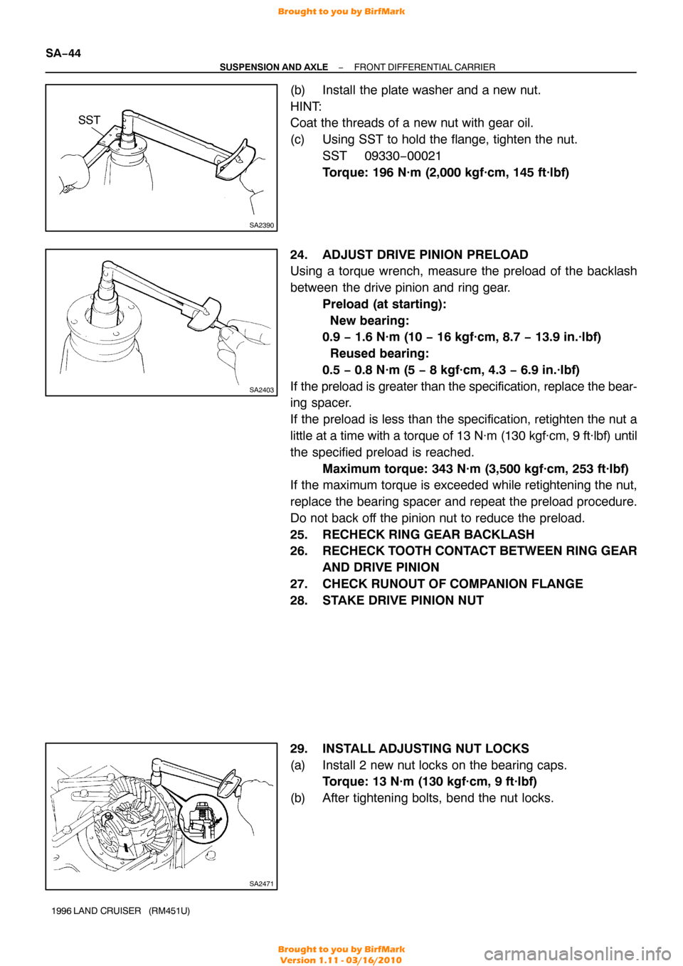
(b) Install the plate washer and a new nut.
HINT:
Coat the threads of a new nut with gear oil.
(c) Using SST to hold the flange, tighten the nut.
SST 09330−00021
Torque: 196 N·m (2,000 kgf·cm, 145 ft·lbf)
24. ADJUST DRIVE PINION PRELOAD
Using a torque wrench, measure the preload of the backlash
between the drive pinion and ring gear. Preload (at starting):
New bearing:
0.9 − 1.6 N·m (10 − 16 kgf·cm, 8.7 − 13.9 in.·lbf)
Reused bearing:
0.5 − 0.8 N·m (5 − 8 kgf·cm, 4.3 − 6.9 in.·lbf)
If the preload is greater than the specification, replace the bear-
ing spacer.
If the preload is less than the specification, retighten the nut a
little at a time with a torque of 13 N·m (130 kgf·cm, 9 ft·lbf) until
the specified preload is reached. Maximum torque: 343 N·m (3,500 kgf·cm, 253 ft·lbf)
If the maximum torque is exceeded while retightening the nut,
replace the bearing spacer and repeat the preload procedure.
Do not back off the pinion nut to reduce the preload.
25. RECHECK RING GEAR BACKLASH
26. RECHECK TOOTH CONTACT BETWEEN RING GEAR
AND DRIVE PINION
27. CHECK RUNOUT OF COMPANION FLANGE
28. STAKE DRIVE PINION NUT
29. INSTALL ADJUSTING NUT LOCKS
(a) Install 2 new nut locks on the bearing caps. Torque: 13 N·m (130 kgf·cm, 9 ft·lbf)
(b) After tightening bolts, bend the nut locks.
Brought to you by BirfMark
Brought to you by BirfMark
Version 1.11 - 03/16/2010
Page 1130 of 1399
SA1V9−01
−
SUSPENSION AND AXLE REAR AXLE HUB
SA−67
1996 LAND CRUISER (RM451U)
REMOVAL
1. REMOVE REAR WHEEL
2. REMOVE REAR AXLE SHAFT (See page SA−63 )
3. REMOVE BRAKE CALIPER AND DISC (See page BR−34 )
4. DISCONNECT ABS SPEED SENSOR
Remove the bolt and disconnect the ABS speed sensor.
5. REMOVE REAR AXLE BEARING LOCK NUT
(a) Remove the 2 screws from the lock nut.
(b) Using SST, remove the lock nut. SST 09509−25011
6. REMOVE REAR AXLE HUB
(a) Pull out the axle hub, remove the lock nut plate and outer
bearing.
(b) Remove the axle hub.
Brought to you by BirfMark
Brought to you by BirfMark
Version 1.11 - 03/16/2010
Page 1131 of 1399
SA1VA−01
R13157
Brass Bar
Positions
R13158
SST
R13159
SA−68
−
SUSPENSION AND AXLE REAR AXLE HUB
1996 LAND CRUISER (RM451U)
REPLACEMENT
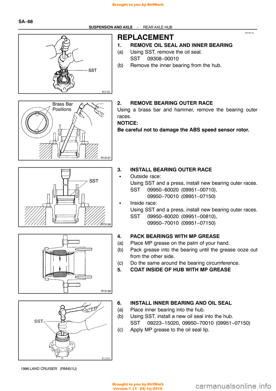
1. REMOVE OIL SEAL AND INNER BEARING
(a) Using SST, remove the oil seal.
SST 09308−00010
(b) Remove the inner bearing from the hub.
2. REMOVE BEARING OUTER RACE
Using a brass bar and hammer, remove the bearing outer
races.
NOTICE:
Be careful not to damage the ABS speed sensor rotor.
3. INSTALL BEARING OUTER RACE
�Outside race:
Using SST and a press, install new bearing outer races.
SST 09950−60020 (09951 −00710),
09950 −70010 (09951 −07150)
�Inside race:
Using SST and a press, install new bearing outer races.
SST 09950−60020 (09951 −00810),
09950 −70010 (09951 −07150)
4. PACK BEARINGS WITH MP GREASE
(a) Place MP grease on the palm of your hand.
(b) Pack grease into the bearing until the grease ooze out from the other side.
(c) Do the same around the bearing circumference.
5. COAT INSIDE OF HUB WITH MP GREASE
6. INSTALL INNER BEARING AND OIL SEAL
(a) Place inner bearing into the hub.
(b) Using SST, install a new oil seal into the hub. SST 09223−15020, 09950 −70010 (09951−07150)
(c) Apply MP grease to the oil seal lip.
Brought to you by BirfMark
Brought to you by BirfMark
Version 1.11 - 03/16/2010
Page 1132 of 1399
SA1VB−01
R08001
Lock Nut Mark
Axle Housing
Mark
−
SUSPENSION AND AXLE REAR AXLE HUB
SA−69
1996 LAND CRUISER (RM451U)
INSTALLATION
1. INSTALL REAR AXLE HUB
(a) Clean the hub installation position of the axle housing and
apply MP grease thinly.
(b) Place the axle hub to the axle housing.
NOTICE:
Be careful not to damage the oil seal.
(c) Install the outer bearing.
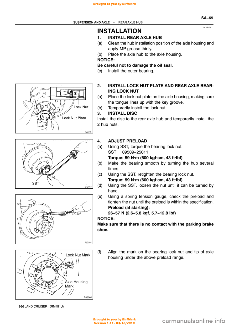
2. INSTALL LOCK NUT PLATE AND REAR AXLE BEAR- ING LOCK NUT
(a) Place the lock nut plate on the axle housing, making sure
the tongue lines up with the key groove.
(b) Temporarily install the lock nut.
3. INSTALL DISC
Install the disc to the rear axle hub and temporarily install the
2 hub nuts.
4. ADJUST PRELOAD
(a) Using SST, torque the bearing lock nut.SST 09509−25011
Torque: 59 N·m (600 kgf·cm, 43 ft·lbf)
(b) Make the bearing smooth by turning the hub several
times.
(c) Using the SST, retighten the bearing lock nut. Torque: 59 N·m (600 kgf·cm, 43 ft·lbf)
(d) Using the SST, loosen the nut until it can be turned by
hand.
(e) Using a spring tension gauge, check the preload and tighten the nut until the preload is within the specification.
Preload (at starting):
26−57 N (2.6−5.8 kgf, 5.7−12.8 lbf)
NOTICE:
Make sure that there is no contact with the parking brake
shoe.
(f) Align the mark on the bearing lock nut and tip of axle housing under the above preload range.
Brought to you by BirfMark
Brought to you by BirfMark
Version 1.11 - 03/16/2010