Page 76 of 1399

AC2R5−01
N06158
−
AIR CONDITIONING COMPRESSOR AND MAGNETIC CLUTCH
AC−33
1360
Author�: Date�:
1996 LAND CRUISER (RM451U)
COMPRESSOR AND MAGNETIC
CLUTCH
ON−VEHICLE INSPECTION
1. INSTALL MANIFOLD GAUGE SET (See page AC−18 )
2. START ENGINE
Run the engine at 1,500 rpm.
3. INSPECT COMPRESSOR FOR METALLIC SOUND
Check if there is a metallic sound from the compressor when the
A/C switch is on.
If metallic sound is heard, replace the compressor assembly.
4. INSPECT REFRIGERANT PRESSURE (See page AC−5 )
5. STOP ENGINE
6. INSPECT VISUALLY FOR LEAKAGE OF REFRIGER- ANT FROM SAFETY SEAL
Using a gas leak detector, check for leakage of refrigerant.
If there is any leakage, replace the compressor assembly.
7. REMOVE MANIFOLD GAUGE SET (See page
AC−19 )
8. MAKE THESE VISUAL CHECKS:
(a) Leakage of grease from the clutch bearing.
(b) Signs of oil on the pressure plate or rotor. Repair or replace, as necessary.
9. INSPECT MAGNETIC CLUTCH BEARING FOR NOISE
(a) Start engine.
(b) Check for abnormal noise from near the compressor when the A/C switch is OFF.
If abnormal noise is being emitted, replace the magnetic clutch.
10. INSPECT MAGNETIC CLUTCH
(a) Disconnect the connector from the magnetic clutch.
(b) Connect the positive (+) lead from the battery to the termi-
nal on the magnetic clutch connector and the negative ( −)
lead to the body ground.
(c) Check that the magnetic clutch is energized.
If operation is not as specified, replace the magnetic clutch.
Brought to you by BirfMark
Brought to you by BirfMark
Version 1.11 - 03/16/2010
Page 360 of 1399

BR1CX−03
BR0251
−
BRAKE FRONT BRAKE CALIPER
BR−27
1996 LAND CRUISER (RM451U)
INSPECTION
1. MEASURE PAD LINING THICKNESS
Using a ruler, measure the pad lining thickness.
Standard thickness: 9.5 mm (0.374 in.)
Minimum thickness: 1.0 mm (0.039 in.)
Replace the pad if the thickness is less than the minimum (the
1.0 mm slit is no longer visible), or if it shows signs of uneven
wear.
2. MEASURE DISC THICKNESS
Using a micrometer, measure the disc thickness. Standard thickness: 32.0 mm (1.260 in.)
Minimum thickness: 30.0 mm (1.181 in.)
If the disc is scored or worn, or if its thickness is less than the
minimum, repair or replace the disc.
3. MEASURE DISC RUNOUT
Using a dial indicator, measure the disc runout at a position 10
mm (0.39 in.) from the outside edge. Maximum disc runout: 0.15 mm (0.0059 in.)
If the runout is greater than the maximum, replace the disc or
grind it on a ”On−Car” brake lathe.
HINT:
Before measuring the runout, confirm that the front hub bearing
play is within the specification.
4. IF NECESSARY, REPLACE DISC
(a) Remove the front axle hub (See page SA−7).
(b) Remove the disc from the axle hub.
(c) Install a new disc and torque the bolts. Torque: 74 N·m (750 kgf·cm, 54 ft·lbf)
(d) Install the axle hub and adjust the front bearing preload (See page SA−9 ).
Brought to you by BirfMark
Brought to you by BirfMark
Version 1.11 - 03/16/2010
Page 415 of 1399

P13535
Length
Z04143
Positive (+)
Terminal
Rectifier
Terminal
Ohmmeter
Z04144
Negative (− )
Terminal
Ohmmeter
P00644
CH1026
−
CHARGING GENERATOR
CH−13
1996 LAND CRUISER (RM451U)
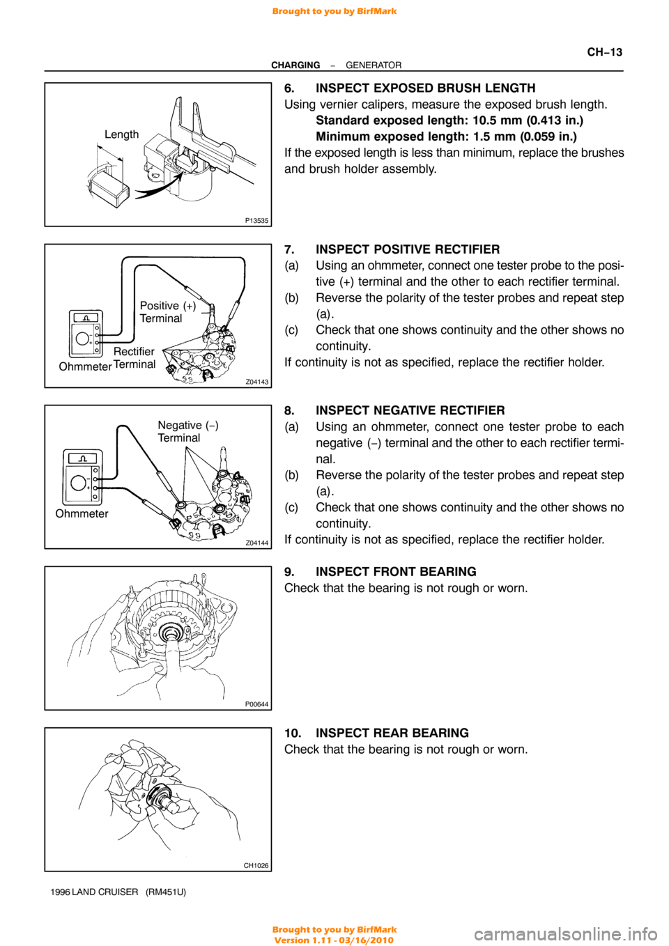
6. INSPECT EXPOSED BRUSH LENGTH
Using vernier calipers, measure the exposed brush length.
Standard exposed length: 10.5 mm (0.413 in.)
Minimum exposed length: 1.5 mm (0.059 in.)
If the exposed length is less than minimum, replace the brushes
and brush holder assembly.
7. INSPECT POSITIVE RECTIFIER
(a) Using an ohmmeter, connect one tester probe to the posi- tive (+) terminal and the other to each rectifier terminal.
(b) Reverse the polarity of the tester probes and repeat step (a).
(c) Check that one shows continuity and the other shows no
continuity.
If continuity is not as specified, replace the rectifier holder.
8. INSPECT NEGATIVE RECTIFIER
(a) Using an ohmmeter, connect one tester probe to each negative ( −) terminal and the other to each rectifier termi-
nal.
(b) Reverse the polarity of the tester probes and repeat step
(a).
(c) Check that one shows continuity and the other shows no continuity.
If continuity is not as specified, replace the rectifier holder.
9. INSPECT FRONT BEARING
Check that the bearing is not rough or worn.
10. INSPECT REAR BEARING
Check that the bearing is not rough or worn.
Brought to you by BirfMark
Brought to you by BirfMark
Version 1.11 - 03/16/2010
Page 416 of 1399
CH0HQ−01
P22368
SST
P22369
SST
N00581
SST
CH−14
−
CHARGING GENERATOR
1996 LAND CRUISER (RM451U)
REPLACEMENT
1. REPLACE FRONT BEARING
(a) Remove the 4 screws and bearing retainer.
(b) Using SST and a press, press out the bearing. SST 09950−60010 (09951 −00260, 09952−06010)
(c) Using SST and a press, press in a new bearing. SST 09950−60010 (09951 −00500)
(d) Install the bearing retainer with the 4 screws. Torque: 2.6 N·m (27 kgf·cm, 23 in.·lbf)
2. REPLACE REAR BEARING
(a) Using SST , remove the bearing cover (outside) and bear-
ing.
SST 09820−00021
NOTICE:
Be careful not to damage the fan.
(b) Remove the bearing cover (inside).
Brought to you by BirfMark
Brought to you by BirfMark
Version 1.11 - 03/16/2010
Page 417 of 1399
P05052
Bearring Cover
N00578
SST
P00074
SST
−
CHARGING GENERATOR
CH−15
1996 LAND CRUISER (RM451U)
(c) Place the bearing cover (inside) on the rotor.
(d) Using SST and a press, press in a new bearing.
SST 09820−00030
(e) Using SST, push in the bearing cover (outside). SST 09285−76010
Brought to you by BirfMark
Brought to you by BirfMark
Version 1.11 - 03/16/2010
Page 818 of 1399

P22143A16076
2 Dot Marks
−
ENGINE MECHANICAL CYLINDER HEAD
EM−33
1996 LAND CRUISER (RM451U)
(d) Remove the camshaft timing gear and chain from the in-
take camshaft and leave on the slipper and damper.
35. REMOVE CAMSHAFTS
NOTICE:
Since the thrust clearance of the camshaft is small, the
camshaft must be kept level while it is being removed. If the
camshaft is not kept level, the portion of the cylinder head
receiving the shaft thrust may crack or be damaged, caus-
ing the camshaft to seize or break. To avoid this, the follow-
ing steps should be carried out.
(a) Remove the exhaust camshaft. (1) Bring the service bolt hole of the driven sub −gear
upward by turning the hexagon wrench head por-
tion of the exhaust camshaft with a wrench.
(2) Secure the exhaust camshaft sub −gear to the main
gear with a service bolt.
Recommended service bolt:
Thread diameter6 mm
Thread pitch1.0 mm
Bolt length16 − 20 mm (0.63 − 0.79 in.)
HINT:
When removing the camshaft, make sure that the torsional
spring force of the sub −gear has been eliminated by the above
operation.
(3) Set the timing mark (2 dot marks) of the camshaftdriven gear at approx. 35 ° angle by turning the
hexagon wrench head portion of the intake cam-
shaft with a wrench.
(4) Lightly push the camshaft towards the rear without applying excessive force.
(5) Loosen and remove the No. 1 bearing cap bolts, al-
ternately loosening the left and right bolts uniformly.
Brought to you by BirfMark
Brought to you by BirfMark
Version 1.11 - 03/16/2010
Page 819 of 1399

P22567A16077
2 Dot Marks
EM−34
−
ENGINE MECHANICAL CYLINDER HEAD
1996 LAND CRUISER (RM451U)
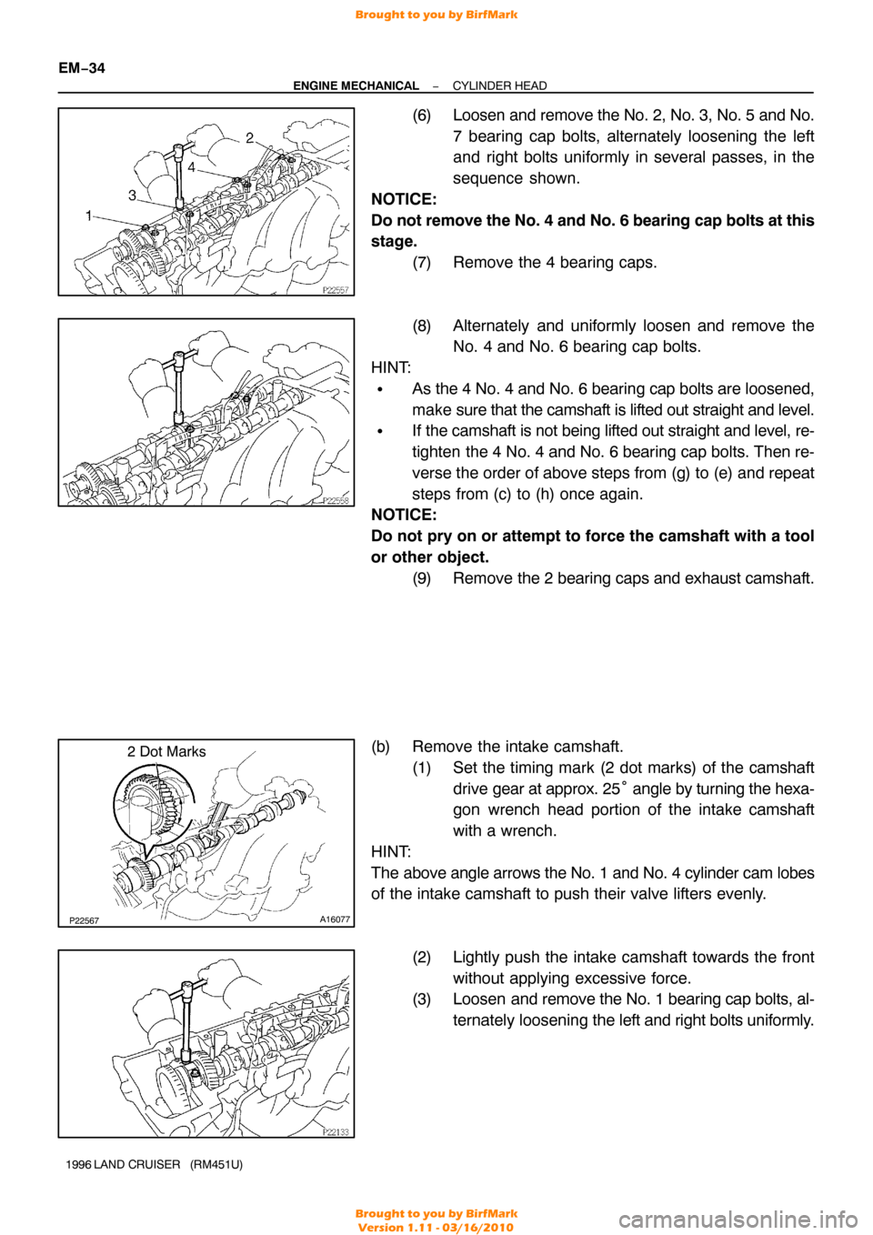
(6) Loosen and remove the No. 2, No. 3, No. 5 and No.
7 bearing cap bolts, alternately loosening the left
and right bolts uniformly in several passes, in the
sequence shown.
NOTICE:
Do not remove the No. 4 and No. 6 bearing cap bolts at this
stage. (7) Remove the 4 bearing caps.
(8) Alternately and uniformly loosen and remove theNo. 4 and No. 6 bearing cap bolts.
HINT:
�As the 4 No. 4 and No. 6 bearing cap bolts are loosened,
make sure that the camshaft is lifted out straight and level.
�If the camshaft is not being lifted out straight and level, re-
tighten the 4 No. 4 and No. 6 bearing cap bolts. Then re-
verse the order of above steps from (g) to (e) and repeat
steps from (c) to (h) once again.
NOTICE:
Do not pry on or attempt to force the camshaft with a tool
or other object.
(9) Remove the 2 bearing caps and exhaust camshaft.
(b) Remove the intake camshaft. (1) Set the timing mark (2 dot marks) of the camshaftdrive gear at approx. 25 ° angle by turning the hexa-
gon wrench head portion of the intake camshaft
with a wrench.
HINT:
The above angle arrows the No. 1 and No. 4 cylinder cam lobes
of the intake camshaft to push their valve lifters evenly.
(2) Lightly push the intake camshaft towards the frontwithout applying excessive force.
(3) Loosen and remove the No. 1 bearing cap bolts, al-
ternately loosening the left and right bolts uniformly.
Brought to you by BirfMark
Brought to you by BirfMark
Version 1.11 - 03/16/2010
Page 820 of 1399

−
ENGINE MECHANICAL CYLINDER HEAD
EM−35
1996 LAND CRUISER (RM451U)
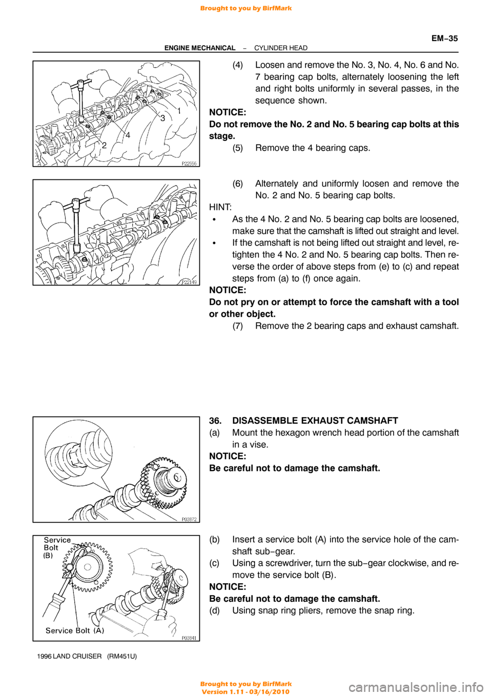
(4) Loosen and remove the No. 3, No. 4, No. 6 and No.
7 bearing cap bolts, alternately loosening the left
and right bolts uniformly in several passes, in the
sequence shown.
NOTICE:
Do not remove the No. 2 and No. 5 bearing cap bolts at this
stage. (5) Remove the 4 bearing caps.
(6) Alternately and uniformly loosen and remove theNo. 2 and No. 5 bearing cap bolts.
HINT:
�As the 4 No. 2 and No. 5 bearing cap bolts are loosened,
make sure that the camshaft is lifted out straight and level.
�If the camshaft is not being lifted out straight and level, re-
tighten the 4 No. 2 and No. 5 bearing cap bolts. Then re-
verse the order of above steps from (e) to (c) and repeat
steps from (a) to (f) once again.
NOTICE:
Do not pry on or attempt to force the camshaft with a tool
or other object.
(7) Remove the 2 bearing caps and exhaust camshaft.
36. DISASSEMBLE EXHAUST CAMSHAFT
(a) Mount the hexagon wrench head portion of the camshaft in a vise.
NOTICE:
Be careful not to damage the camshaft.
(b) Insert a service bolt (A) into the service hole of the cam-
shaft sub−gear.
(c) Using a screwdriver, turn the sub− gear clockwise, and re-
move the service bolt (B).
NOTICE:
Be careful not to damage the camshaft.
(d) Using snap ring pliers, remove the snap ring.
Brought to you by BirfMark
Brought to you by BirfMark
Version 1.11 - 03/16/2010