Page 874 of 1399

EXAMPLE: Cylinder block ”2” + Crankshaft ”1”= Total number 3 (Use bearing ”3”)
Number marked
Cylinder block
Crankshaft
Use bearing 123
2
2 22
3
3 3
3 3
4445 56
111
−
ENGINE MECHANICAL CYLINDER BLOCK
EM−89
1996 LAND CRUISER (RM451U)
(j) Measure the Plastigage at its widest point.
Standard clearance:
STD0.042 − 0.060 mm (0.0017 − 0.0024 in.)
U/S 0.250.041 − 0.081 mm (0.0016 − 0.0032 in.)
Maximum clearance: 0.10 mm (0.0039 in.)
If the oil clearance is greater than maximum, replace the bear-
ings. If necessary, grind or replace the crankshaft.
HINT:
If using a standard bearing, replace with one having the same
number. If the number of the bearing cannot be determined, se-
lect the correct bearing by adding together the numbers im-
printed on the cylinder block and crankshaft, then selecting the
bearing with the same number as the total. There are 5 sizes
of standard bearings, marked ”2”, ”3”, ”4”, ”5” and ”6”\
accorking-
ly.
Reference
Cylinder block main journal bore diameter:
Mark ”1”74.026 − 74.032 mm (2.9144 − 2.9146 in.)
Mark ”2”74.032 − 74.038 mm (2.9146 − 2.9149 in.)
Mark ”3”74.038 − 74.044 mm (2.9149 − 2.9151 in.)
Crankshaft main journal diameter:
Mark ”1”68.994 − 69.000 mm (2.7163 − 2.7165 in.)
Mark ”2”68.988 − 68.994 mm (2.7161 − 2.7163 in.)
Mark ”3”68.982 − 68.988 mm (2.7158 − 2.7161 in.)
Standard bearing center wall thickness:
Mark ”2”2.489 − 2.492 mm (0.0980 − 0.0981 in.)
Mark ”2”2.492 − 2.495 mm (0.0981 − 0.0982 in.)
Mark ”3”2.495 − 2.498 mm (0.0982 − 0.0983 in.)
Mark ”4”2.498 − 2.501 mm (0.0983 − 0.0985 in.)
Mark ”5”2.501 − 2.504 mm (0.0985 − 0.0986 in.)
(k) Completely remove the Plastigage.
18. REMOVE CRANKSHAFT
(a) Lift out the crankshaft.
(b) Remove the upper main bearings and upper thrust wash-
ers from the cylinder block.
HINT:
Arrange the main bearings and thrust washers in correct order.
Brought to you by BirfMark
Brought to you by BirfMark
Version 1.11 - 03/16/2010
Page 876 of 1399
P03870
−
ENGINE MECHANICAL CYLINDER BLOCK
EM−91
1996 LAND CRUISER (RM451U)
23. DISCONNECT CONNECTING ROD FROM PISTON
(a) Using a small screwdriver, pry out the 2 snap rings.
(b) Gradually heat the piston to 80 − 90°C (176 − 194° F).
(c) Using plastic −faced hammer and brass bar, lightly tap out
the piston pin and remove the connecting rod.
HINT:
�The piston and pin are a matched set.
�Arrange the pistons, pins, rings, connecting rods and
bearings in correct order.
Brought to you by BirfMark
Brought to you by BirfMark
Version 1.11 - 03/16/2010
Page 878 of 1399

−
ENGINE MECHANICAL CYLINDER BLOCK
EM−93
1996 LAND CRUISER (RM451U)
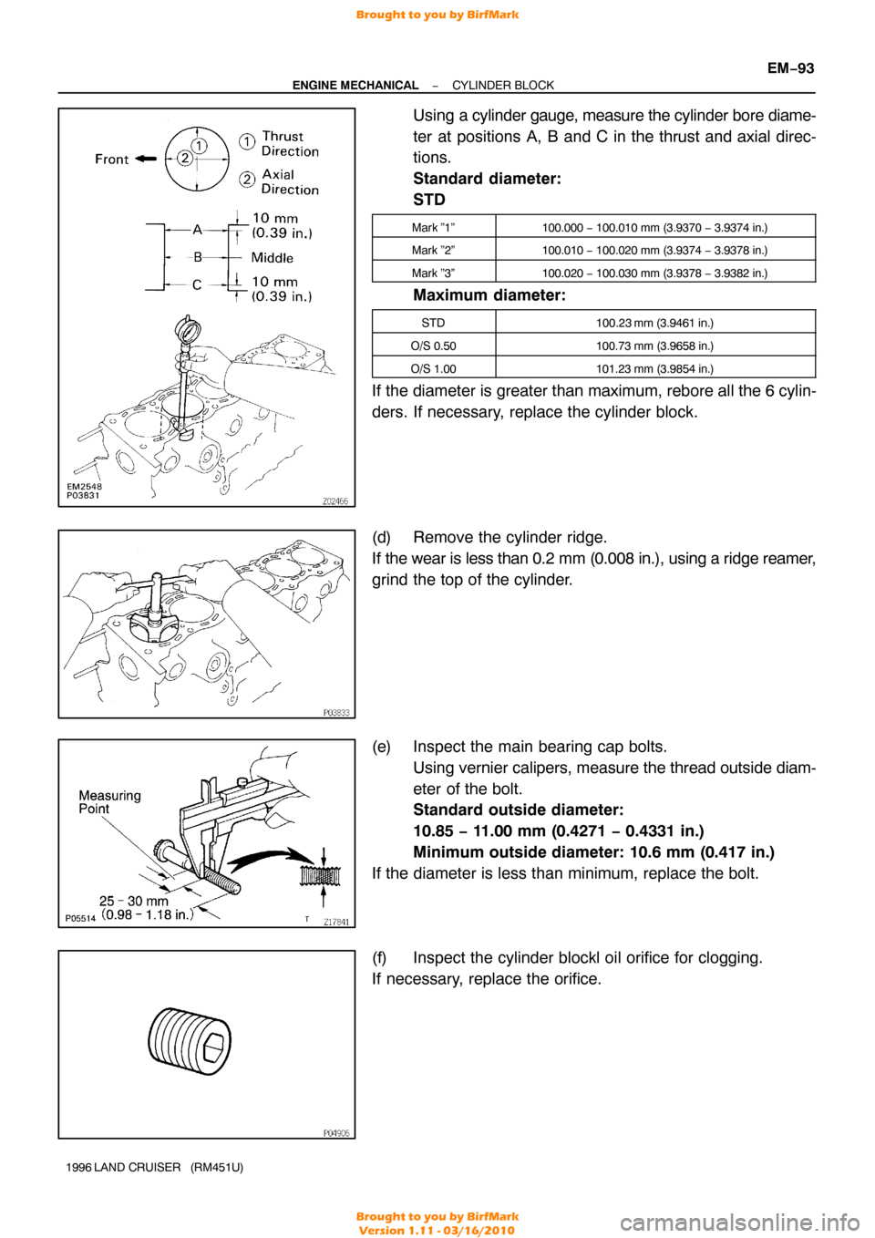
Using a cylinder gauge, measure the cylinder bore diame-
ter at positions A, B and C in the thrust and axial direc-
tions.
Standard diameter:
STD
Mark ”1”100.000 − 100.010 mm (3.9370 − 3.9374 in.)
Mark ”2”100.010 − 100.020 mm (3.9374 − 3.9378 in.)
Mark ”3”100.020 − 100.030 mm (3.9378 − 3.9382 in.)
Maximum diameter:
STD100.23 mm (3.9461 in.)
O/S 0.50100.73 mm (3.9658 in.)
O/S 1.00101.23 mm (3.9854 in.)
If the diameter is greater than maximum, rebore all the 6 cylin-
ders. If necessary, replace the cylinder block.
(d) Remove the cylinder ridge.
If the wear is less than 0.2 mm (0.008 in.), using a ridge reamer,
grind the top of the cylinder.
(e) Inspect the main bearing cap bolts.
Using vernier calipers, measure the thread outside diam-
eter of the bolt.
Standard outside diameter:
10.85 − 11.00 mm (0.4271 − 0.4331 in.)
Minimum outside diameter: 10.6 mm (0.417 in.)
If the diameter is less than minimum, replace the bolt.
(f) Inspect the cylinder blockl oil orifice for clogging.
If necessary, replace the orifice.
Brought to you by BirfMark
Brought to you by BirfMark
Version 1.11 - 03/16/2010
Page 879 of 1399
EM−94
−
ENGINE MECHANICAL CYLINDER BLOCK
1996 LAND CRUISER (RM451U)
3. INSPECT BEARING OF OIL PUMP DRIVE SHAFT
GEAR
Check the bearing for pitting and scratches.
If the bearing is damaged, replace the cylinder block.
4. CLEAN PISTON
(a) Using a gasket scraper, remove the carbon from the pis-
ton top.
(b) Using a groove cleaning tool or broken ring, clean the pis-
ton ring grooves.
(c) Using solvent and a brush, thoroughly clean the piston.
NOTICE:
Do not use a wire brush.
5. INSPECT PISTON AND CONNECTING ROD
(a) Inspect the piston oil clearance.
HINT:
There are 3 sizes of the standard piston diameter , marked ”1”,
”2” and ”3”. The mark is stamped on the piston top.
Brought to you by BirfMark
Brought to you by BirfMark
Version 1.11 - 03/16/2010
Page 883 of 1399

EM−98
−
ENGINE MECHANICAL CYLINDER BLOCK
1996 LAND CRUISER (RM451U)
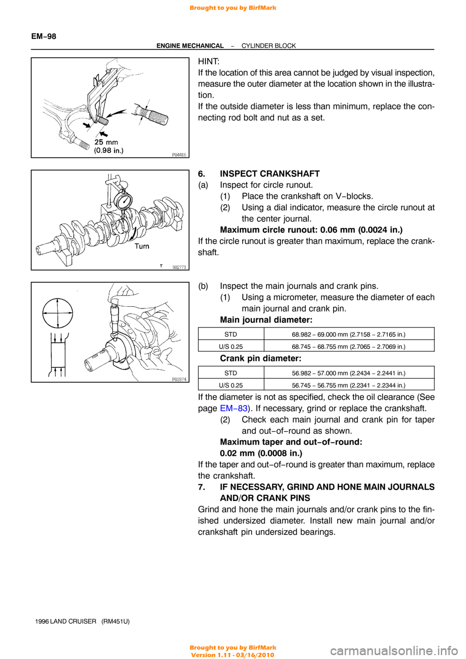
HINT:
If the location of this area cannot be judged by visual inspection,
measure the outer diameter at the location shown in the illustra-
tion.
If the outside diameter is less than minimum, replace the con-
necting rod bolt and nut as a set.
6. INSPECT CRANKSHAFT
(a) Inspect for circle runout. (1) Place the crankshaft on V−blocks.
(2) Using a dial indicator, measure the circle runout atthe center journal.
Maximum circle runout: 0.06 mm (0.0024 in.)
If the circle runout is greater than maximum, replace the crank-
shaft.
(b) Inspect the main journals and crank pins. (1) Using a micrometer, measure the diameter of each
main journal and crank pin.
Main journal diameter:
STD68.982 − 69.000 mm (2.7158 − 2.7165 in.)
U/S 0.2568.745 − 68.755 mm (2.7065 − 2.7069 in.)
Crank pin diameter:
STD56.982 − 57.000 mm (2.2434 − 2.2441 in.)
U/S 0.2556.745 − 56.755 mm (2.2341 − 2.2344 in.)
If the diameter is not as specified, check the oil clearance (See
page EM−83 ). If necessary, grind or replace the crankshaft.
(2) Check each main journal and crank pin for taper and out−of−round as shown.
Maximum taper and out−of−round:
0.02 mm (0.0008 in.)
If the taper and out −of− round is greater than maximum, replace
the crankshaft.
7. IF NECESSARY, GRIND AND HONE MAIN JOURNALS
AND/OR CRANK PINS
Grind and hone the main journals and/or crank pins to the fin-
ished undersized diameter. Install new main journal and/or
crankshaft pin undersized bearings.
Brought to you by BirfMark
Brought to you by BirfMark
Version 1.11 - 03/16/2010
Page 889 of 1399
EM−104
−
ENGINE MECHANICAL CYLINDER BLOCK
1996 LAND CRUISER (RM451U)
(c) Position the piston rings so that the ring ends are as shown.
NOTICE:
Do not align the ring ends.
3. INSTALL BEARINGS
(a) Align the bearing claw with the groove of the connecting
rod or connecting rod cap.
(b) Install the bearings in the connecting rod and connecting rod cap.
4. INSTALL CYLINDER BLOCK ORIFICE
5. INSTALL OIL NOZZLES AND CHECK VALVES
(a) Align the pin of the oil nozzle with the pin hole of the cylin-
der block.
(b) Install the oil nozzle with the check valve. Install the 6 oil nozzles and check valves.
Torque: 25 N·m (250 kgf·cm, 18 ft·lbf)
Brought to you by BirfMark
Brought to you by BirfMark
Version 1.11 - 03/16/2010
Page 890 of 1399
P03813
P05520A16079
−
ENGINE MECHANICAL CYLINDER BLOCK
EM−105
1996 LAND CRUISER (RM451U)
6. INSTALL MAIN BEARINGS
(a) Align the bearing claw with the claw groove of the cylinder
block, and push in the 7 upper bearings.
(b) Align the bearing claw with the claw groove of the main bearing cap, and push in the 7 lower bearings.
HINT:
A number is marked on each main bearing cap to indicate the
installation position.
7. INSTALL UPPER THRUST WASHERS
Install the 2 thrust washers under the No.4 journal position of
the cylinder block with the oil grooves facing outward.
8. PLACE CRANKSHAFT ON CYLINDER BLOCK
9. INSTALL MAIN BEARING CAPS AND LOWER THRUST WASHERS
(a) Place the main bearing caps and lower thrust washers on
the cylinder block.
(1) Install the 2 thrust washers on the No.4 bearing cap
with the grooves facing outward.
Brought to you by BirfMark
Brought to you by BirfMark
Version 1.11 - 03/16/2010
Page 891 of 1399

EM−106
−
ENGINE MECHANICAL CYLINDER BLOCK
1996 LAND CRUISER (RM451U)
(2) Install the 7 main bearing caps in their proper loca-
tions.
HINT:
Each bearing cap has a number and front mark.
(b) Install the main bearing cap bolts.
HINT:
�The main bearing cap bolts are tightened in 2 progressive
steps (steps (b) and (d)).
�If any of the main bearing cap bolts is broken or deformed,
replace it.
(1) Apply a light coat of engine oil on the threads and
under the heads of the main bearings cap bolts.
(2) Install and uniformly tighten the 14 bolts of the main
bearing caps, in several passes, in the sequence
shown.
Torque: 74 N·m (750 kgf·cm, 54 ft·lbf)
If any one of the main bearing cap bolts does not meet the
torque specification, replace the main bearing cap bolt.
(3) Mark the front of the main bearing cap bolt withpaint.
(4) Retighten the main bearing cap bolts by 90 ° in the
numerical order shown above.
(5) Check that the painted mark is now at a 90° angle
to the front.
(c) Check that the crankshaft turns smoothly.
(d) Check that the crankshaft thrust clearance (See page EM−83 ).
10. INSTALL PISTON AND CONNECTING ROD AS- SEMBLIES
(a) Cover the connecting rod bolts with a short piece of hose
to protect the crankshaft from damage.
Brought to you by BirfMark
Brought to you by BirfMark
Version 1.11 - 03/16/2010