Page 318 of 1399
BO399−01
BO−78
−
BODY INSTRUMENT PANEL
1996 LAND CRUISER (RM451U)
DISASSEMBLY
1. REMOVE GLOVE COMPARTMENT DOOR RE- INFORCEMENT
2. REMOVE NO. 4 HEATER TO REGISTER DUCT
3. REMOVE NO. 5 HEATER TO REGISTER DUCT
4. REMOVE NO. 2 REGISTER
5. REMOVE GLOVE COMPARTMENT DOOR LOCK STRIKER PLATE
6. REMOVE FRONT PASSENGER AIRBAG ASSEMBLY (See page RS−22 )
(a) Remove the 4 bolts and 2 nuts, and remove front passen-
ger airbag assembly.
(b) Pry up the 6 clips shown in the illustration and remove the airbag door.
CAUTION:
�Do not store the front passenger airbag assembly
with the airbag deployment direction facing down.
�Never disassemble the front passenger airbag as-
sembly.
7. REMOVE NO. 3 CONSOLE MOUNTING BRACKET
8. REMOVE NO. 1 HEATER TO REGISTER DUCT
9. REMOVE NO. 2 STAY
Brought to you by BirfMark
Brought to you by BirfMark
Version 1.11 - 03/16/2010
Page 333 of 1399

−
BODY SEAT BELT
BO−93
1996 LAND CRUISER (RM451U)
SEAT BELT
INSPECTION
CAUTION:
Replace the seat belt assembly")
BO0632
BO39M−01
BO0633
15°
45°
N10070
Full Belt Length
minus 200 mm
(7.87 in.)
−
BODY SEAT BELT
BO−93
1996 LAND CRUISER (RM451U)
SEAT BELT
INSPECTION
CAUTION:
Replace the seat belt assembly (outer belt, inner belt, bolts,
nuts or sill −bar) if it has been used in a severe impact. The
entire assembly should be replaced even if damage is not
obvious.
1. All seat belts: RUNNING TEST (IN SAFE AREA)
(a) Fasten the front seat belts.
(b) Drive the car at 10 mph (16 km/h) and make a very hard stop.
Check that the belt locks and cannot be extended at this
time.
HINT:
Conduct this test in a safe area. If the belt does not lock, remove
the belt mechanism assembly and conduct the following static
check. Also, whenever installing a new belt assembly, verify the
proper operation before installation.
2. Driver ’s seat belt (ELR): STATIC TEST
(a) Make sure that the belt locks when pulled out quickly.
(b) Remove the locking retractor assembly.
(c) Tilt the retractor slowly.
(d) Make sure that the belt can be pulled out at a tilt of 15 de-
grees or less, and cannot be pulled out at over 45 degrees
of tilt.
If a problem is found, replace the assembly.
3. Except driver’s seat belt (ALR/ELR):
STATIC TEST
(a) Make sure that the belt locks when pulled out quickly.
(b) Remove the locking retractor assembly.
(c) Pull out the whole belt and measure the length of the whole belt.
Then retract the belt slightly and pull it out again.
(d) Make sure that the belt cannot be extended further.
If a problem is found, replace the assembly.
(e) Retract the whole belt, then pull it out to the full length mi-
nus 200 mm (7.87 in.).
(f) Tilt the retractor slowly.
(g) Make sure that the belt can be pulled out at a tilt of 15 de-
grees or less, and cannot be pulled out at over 45 degrees
of tilt.
If a problem is found, replace the assembly.
Brought to you by BirfMark
Brought to you by BirfMark
Version 1.11 - 03/16/2010
Page 337 of 1399

BRAKE FLUID
BLEEDING
HINT:
If any work is done on the brake system or if air is suspected in
the")
BR1CE−01
R13494
R00252
BR−4
−
BRAKE BRAKE FLUID
986
Author�: Date�:
1996 LAND CRUISER (RM451U)
BRAKE FLUID
BLEEDING
HINT:
If any work is done on the brake system or if air is suspected in
the brake lines, bleed the system of air.
NOTICE:
Do not let brake fluid remain on a painted surface. Wash it
off immediately.
1. FILL BRAKE RESERVOIR WITH BRAKE FLUID
Check the fluid level in the reservoir after bleeding each wheel.
Add fluid, if necessary. Fluid: SAE J1703 or FMVSS No.116 DOT3
2. BLEED MASTER CYLINDER
HINT:
If the master cylinder has been disassembled or if the reservoir
becomes empty, bleed the air from the master cylinder.
(a) Disconnect the brake lines from the master cylinder.
(b) Slowly depress the brake pedal and hold it.
(c) Block off the outlet plugs with your fingers, and release the brake pedal.
(d) Repeat (b) and (c) 3 or 4 times.
3. CONNECT VINYL TUBE TO BRA KE CALIPER BLEED-
ER PLUG
Insert other end of the tube in a half −full container of brake fluid.
NOTICE:
Begin bleeding air from the brake caliper with the longest
hydraulic line.
4. BLEED BRAKE LINE
(a) Slowly depress the brake pedal several times.
Brought to you by BirfMark
Brought to you by BirfMark
Version 1.11 - 03/16/2010
Page 339 of 1399

BRAKE PEDAL
ON−VEHICLE INSPECTI")
BR3295
Push RodStop Light Switch
Pedal Height
BR1CF−04
BR4980
A
BR0016
Pedal Freeplay
BR−6
−
BRAKE BRAKE PEDAL
988
Author�: Date�:
1996 LAND CRUISER (RM451U)
BRAKE PEDAL
ON−VEHICLE INSPECTION
1. CHECK PEDAL HEIGHT
Pedal height from dash panel:
167.5 − 177.5 mm (6.594 − 6.988 in.)
2. IF NECESSARY, ADJUST PEDAL HEIGHT
(a) Disconnect the connector from the stop light switch.
(b) Loosen the stop light switch lock nut and remove the stop
light switch.
(c) Loosen the push rod lock nut.
(d) Adjust the pedal height by turning the pedal push rod.
(e) Tighten the push rod lock nut. Torque: 25 N·m (260 kgf·cm, 19 ft·lbf)
(f) Install the stop light switch and turn it until it lightly con-
tacts the pedal stopper.
(g) Turn the stop light switch back one turn.
(h) Check the clearance (A) between the stop light switch and pedal.
Clearance: 0.5 − 2.4 mm (0.020 − 0.094 in.)
(i) Tighten the stop light switch lock nut.
(j) Connect the connector to the stop light switch.
(k) Check that the stop lights come on when the brake pedal
is depressed, and go off when the brake pedal is re-
leased.
(l) earance (A) between the stop light switch and the pedal
stopper has been adjusted correctly, the pedal freeplay
will meet the specifications.
3. CHECK PEDAL FREEPLAY
(a) Stop the engine and depress the brake pedal several times until there is no more vacuum left in the booster.
(b) Push in the pedal by hand until the beginning of the se- cond resistance is felt. Measure the distance.
Pedal freeplay: 3 − 6 mm (0.12 − 0.24 in.)
HINT:
The freeplay to the 1st resistance is due to the play between the
clevis and pin. This is magnified up to 3 − 6 mm (0.12 − 0.24 in.)
at the pedal.
Brought to you by BirfMark
Brought to you by BirfMark
Version 1.11 - 03/16/2010
Page 341 of 1399
BR4774
BR1CG−01
BR4775
BR−8
−
BRAKE PARKING BRAKE LEVER
990
Author�: Date�:
1996 LAND CRUISER (RM451U)
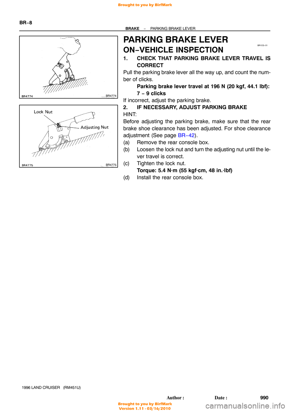
PARKING BRAKE LEVER
ON−VEHICLE INSPECTION
1. CHECK THAT PARKING BRAKE LEVER TRAVEL IS
CORRECT
Pull the parking brake lever all the way up, and count the num-
ber of clicks.
Parking brake lever travel at 196 N (20 kgf, 44.1 lbf):
7 − 9 clicks
If incorrect, adjust the parking brake.
2. IF NECESSARY, ADJUST PARKING BRAKE
HINT:
Before adjusting the parking brake, make sure that the rear
brake shoe clearance has been adjusted. For shoe clearance
adjustment (See page BR−42).
(a) Remove the rear console box.
(b) Loosen the lock nut and turn the adjusting nut until the le-
ver travel is correct.
(c) Tighten the lock nut.
Torque: 5.4 N·m (55 kgf·cm, 48 in.·lbf)
(d) Install the rear console box.
Brought to you by BirfMark
Brought to you by BirfMark
Version 1.11 - 03/16/2010
Page 344 of 1399

DISASSEMBLY
1. REMOVE RESERVOIR
(a) Remove the set screw and pull out the reservoir.
Torque: 1.7 N´m (17.5 kgf´cm,")
BR1CJ-01
R12236
A
-
BRAKE BRAKE MASTER CYLINDER
BR-1 1
1996 LAND CRUISER (RM451U)
DISASSEMBLY
1. REMOVE RESERVOIR
(a) Remove the set screw and pull out the reservoir.
Torque: 1.7 N´m (17.5 kgf´cm, 15.2 in.´lbf)
(b) Remove the cap and strainer from the reservoir.
2. REMOVE 2 GROMMETS
3. REMOVE BOLT AND CLAMP FROM CYLINDER BODY
4. PLACE CYLINDER IN VISE
5. REMOVE PISTON STOPPER BOLT
Using a screwdriver, push the pistons in all the way and remove
the piston stopper bolt and gasket.
HINT:
Tape the screwdriver tip before use. Torque: 10 N´m (100 kgf´cm, 7 ft´lbf)
6. REMOVE 2 PISTONS AND SPRINGS
(a) Push in the piston with a screwdriver and remove the snap ring with snap ring pliers.
HINT:
Tape the screwdriver tip before use.
(b) Remove the No.1 piston and spring by hand, pulling straight out, not at an angle.
NOTICE:
If pulled out and installed at an angle, there is a possibly
that the cylinder bore could be damaged.
NOTICE:
Be careful not to damage the rubber lips on the pistons.
(c) Place a rag and 2 wooden blocks on the work table, and lightly tap the cylinder flange against the block edges until
the No.2 piston drops out of the cylinder.
HINT:
Make sure that the distance (A) from the rag to the top of the
blocks is at least 100 mm (3.94 in.).
Brought to you by BirfMark
Brought to you by BirfMark
Version 1.11 - 03/16/2010
Page 377 of 1399

REASSEMBLY
Reassembly is in the reverse order of disassembly (See
page BR−40 ).
NOTICE:
Apply high temperature grease and li")
BR1DA−01
BR−44
−
BRAKE PARKING BRAKE
1996 LAND CRUISER (RM451U)
REASSEMBLY
Reassembly is in the reverse order of disassembly (See
page BR−40 ).
NOTICE:
Apply high temperature grease and lithium soap base gly-
col grease to the parts indicated by the arrows (See page
BR−39 ).
1. ADJUST PARKING BRAKE SHOE CLEARANCE
(a) Disconnect the PKB cable from bellcrank and remove the 2 tension springs.
(b) Loosen the stopper bolt.
(c) Temporarily install the hub nuts.
(d) Remove the hole plug.
(e) Turn the adjuster and expand the shoes until the disc
locks.
(f) Return the adjuster 8 notches.
(g) Install the hole plug.
2. ADJUST BELLCRANK
(a) Pull the bellcrank until all play in the interior linkage is tak-
en up.
(b) Screw in the bellcrank adjusting bolt to where it contacts on the dust seal.
(c) Loosen it one turn, and lock it at that position with the lock nut.
Torque: 5.4 N·m (55 kgf·cm, 48 in.·lbf)
(d) Install the bellcrank spring.
(e) Connect the PKB cable to the bellcrank.
3. BEDDING DOWN PARKING BRAKE SHOES AND
DISC
(a) Drive the vehicle at about 50 km/h (31 mph) on a safe, lev-
el and dry road.
(b) With the parking brake release button pushed in, pull on the lever with 88 N (9 kgf, 19.8 lbf) of force.
(c) Drive the vehicle for about 400 meters (0.25 mile) in this condition.
(d) Repeat this procedure 2 or 3 times.
4. RECHECK AND ADJUST PARKING BRAKE LEVER TRAVEL
Brought to you by BirfMark
Brought to you by BirfMark
Version 1.11 - 03/16/2010
Page 384 of 1399
BR−51
1996 LAND CRUISER (RM451U)
REASSEMBLY
1. ASSEMBLE THESE PARTS TO LOAD SENSING
SPRING:
�Load sensing val")
BR1DG−01
BR0070
−
BRAKE LOAD SENSING PROPORTIONING AND BY− PASS
VALVE (LSP & BV)BR−51
1996 LAND CRUISER (RM451U)
REASSEMBLY
1. ASSEMBLE THESE PARTS TO LOAD SENSING
SPRING:
�Load sensing valve boot
�Load sensing spring boot
�4 bushings
�2 rubber plates
�2 collars
HINT:
Apply lithium soap base glycol grease to the parts indicated by
the arrrows. Do not mistake the valve side for the shackle side
of the load sensing spring.
2. INSTALL SHACKLE NO.1 AND NO.2 TO LOAD SENS-
ING SPRING
(a) Install the lock nut and shackle No. 1 to the shackle No. 2.
(b) Torque the bolt and nut through the 2 plate washers. Torque: 18 N·m (185 kgf·cm, 13 ft·lbf)
3. INSTALL LOAD SENSING SPRING TO VALVE BODY
Install the load sensing spring assembly to the load sensing
valve with the clip.
4. INSTALL VALVE BRACKET
(a) Install the set plate to the valve assembly through the valve bracket and temporarily tighten the 2 valve body
mounting nuts.
(b) Torque the bolt and nut through the 2 plate washers. Torque: 18 N·m (185 kgf·cm, 13 ft·lbf)
Brought to you by BirfMark
Brought to you by BirfMark
Version 1.11 - 03/16/2010

DISASSEMBLY
1. REMOVE GLOVE COMPARTMENT DOOR RE- INFORCEMENT
2. REMOVE NO. 4 HEATER TO REGISTER DUCT
3. REMOVE NO. 5 HEATER TO")