Page 1352 of 1399

INSPECTION
1. INSPECT COMMUTATOR FOR OPEN CIRCUIT
Using")
P10584
OhmmeterContinuity
ST0N8−01
P10585
Ohmmeter
No Continuity
P10586
P10587
ST0040
−
STARTING STARTER
ST−7
1996 LAND CRUISER (RM451U)
INSPECTION
1. INSPECT COMMUTATOR FOR OPEN CIRCUIT
Using an ohmmeter, check that there is continuity between the
segments of the commutator.
If there is no continuity between any segment, replace the ar-
mature.
2. INSPECT COMMUTATOR FOR GROUND
Using an ohmmeter, check that there is no continuity between
the commutator and armature coil core.
If there is continuity, replace the armature.
3. INSPECT COMMUTATOR FOR DIRTY AND BURNT
SURFACES
If the surface is dirty or burnt, correct it with sandpaper (No. 400)
or on a lathe.
4. INSPECT COMMUTATOR CIRCLE RUNOUT
(a) Place the commutator on V−blocks.
(b) Using a dial gauge, measure the circle runout. Maximum circle runout: 0.05 mm (0.0020 in.)
If the circle runout is greater than maximum, correct it on a lathe.
5. INSPECT COMMUTATOR DIAMETER
Using vernier calipers, measure the commutator diameter. Standard diameter:
1.4 kW type: 30 mm (1.18 in.)
2.0 kW type: 35 mm (1.38 in.)
Minimum diameter:
1.4 kW type: 29 mm (1.14 in.)
2.0 KW type: 34 mm (1.34 in.)
If the diameter is less than minimum, replace the armature.
6. INSPECT UNDERCUT DEPTH
Check that the undercut depth is clean and free of foreign mate-
rials. Smooth out the edge.
Standard undercut depth:
1.4 kW type: 0.6 mm (0.024 in.)
2.0 kW type: 0.7 mm (0.028 in.)
Minimum undercut depth:
0.2 mm (0.008 in.)
If the undercut depth is less than minimum, correct it with a
hacksaw blade.
Brought to you by BirfMark
Brought to you by BirfMark
Version 1.11 - 03/16/2010
Page 1354 of 1399

Minimum spring installed load:
1.4 kW type: 11.8 N (1.20 kgf, 2.7 lbf)
2.0 kW type: 12.7 N (1.29")
P21088
OhmmeterNo Continuity
P10821
Lock
Free
−
STARTING STARTER
ST−9
1996 LAND CRUISER (RM451U)
Minimum spring installed load:
1.4 kW type: 11.8 N (1.20 kgf, 2.7 lbf)
2.0 kW type: 12.7 N (1.29 kgf, 2.9 lbf)
If the installed load is less than minimum replace the brush
springs.
11. INSPECT BRUSH HOLDER INSULATION
Using an ohmmeter, check that there is no continuity between
the positive (+) and negative ( −) brush holders.
If there is continuity, repair or replace the brush holder.
12. INSPECT GEAR TEETH
Check the gear teeth on the pinion gear, idler gear and clutch
assembly for wear or damage.
If damaged, replace the gear or clutch assembly.
If damaged, also check the drive plate ring gear for wear or
damage.
13. INSPECT CLUTCH PINION GEAR
Hold the starter clutch and rotate the pinion gear clockwise, and
check that it turns freely. Try to rotate the pinion gear counter-
clockwise and check that it locks.
If necessary, replace the clutch assembly.
14. INSPECT REAR BEARING
Turn each bearing by hand while applying inward force.
If resistance is felt or the bearing sticks, replace the bearing.
15. INSPECT FRONT BEARING
Turn each bearing by hand while applying inward force.
If resistance is felt or the bearing sticks, replace the bearing.
Brought to you by BirfMark
Brought to you by BirfMark
Version 1.11 - 03/16/2010
Page 1358 of 1399

(b) Terminal C:
Install these new parts:
(1) Terminal insulator (inside)
(2) Contact plate
(3) Terminal bolt
(4) O−ring
(5) Terminal")
V06796
−
STARTING STARTER
ST−13
1996 LAND CRUISER (RM451U)
(b) Terminal C:
Install these new parts:
(1) Terminal insulator (inside)
(2) Contact plate
(3) Terminal bolt
(4) O−ring
(5) Terminal insulator (outside)
(6) Wave washer
(7) Terminal nut
NOTICE:
Be careful to install the terminal insulators (inside) and
wave washers in the correct direction.
(c) Temporarily tighten the terminal nuts.
7. TIGHTEN TERMINAL NUT
(a) Put a wooden block on the contact plate and press it down with a hand press.
Dimensions of wooden block:
20 x 37 x 40 mm (0.79 x 1.46 x 1.57 in.)
Press force:
981 N (100 kgf, 221 lbf)
NOTICE:
Check the diameter of the hand press ram. Then calculate
the gauge pressure of the press when
981 N (100 kgf, 221 lbf) of force is applied. Gauge pressure:
If the contact plate is not pressed down with the specified pres-
sure, the contact plate may tilt due to coil deformation or the
tightening of the nut.
Brought to you by BirfMark
Brought to you by BirfMark
Version 1.11 - 03/16/2010
Page 1364 of 1399
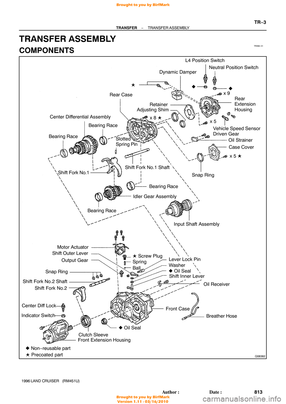
TR0B2−01
Q08382
Dynamic Damper
Rear Case �
Vehicle Speed Sensor
Driven Gear
Center Differential Assembly
Bearing Race
Bearing Race L4 Position Switch
Neutral Position Switch
x 9
�
Rear
Extension
Housing
Oil Strainer Case Cover
x 5 �
Shift Fork No.1
Bearing Race
Idler Gear Assembly
Motor Actuator
Shift Outer Lever
Output Gear
Snap Ring
Shift Fork No.2 Shaft Shift Fork No.2
Center Diff Lock
Indicator Switch
Lever Lock Pin
Washer
� Oil Seal
Shift Inner Lever
Oil Receiver
Breather Hose
Front Case Snap Ring
Shift Fork No.1 Shaft
� Non− reusable part
� Precoated part Front Extension Housing
Clutch Sleeve �
Oil Seal
Bearing Race
�
Slotted
Spring Pin
Input Shaft Assemblyx 5
x 8 �
Retainer
Adjusting Shim
� Screw Plug
Spring
Ball
−
TRANSFER TRANSFER ASSEMBLY
TR−3
813
Author�: Date�:
1996 LAND CRUISER (RM451U)
TRANSFER ASSEMBLY
COMPONENTS
Brought to you by BirfMark
Brought to you by BirfMark
Version 1.11 - 03/16/2010
Page 1365 of 1399

DISASSEMBLY
1. REMOVE BREATHER HOSE
2. REMOVE DYNAMIC DAMPER
Remove the 2 bolts and dynamic damper.
HIN")
TR0CM−01
Q07105
Q07124
FIPG
TR−4
−
TRANSFER TRANSFER ASSEMBLY
1996 LAND CRUISER (RM451U)
DISASSEMBLY
1. REMOVE BREATHER HOSE
2. REMOVE DYNAMIC DAMPER
Remove the 2 bolts and dynamic damper.
HINT:
At the time of reassembly, apply adhesive to the bolt threads. Adhesive: Part No.08833 −00070, THREE BOND 1324
or equivalent
Torque: 37 N·m (380 kgf·cm, 27 ft·lbf)
3. REMOVE MOTOR ACTUATOR
Remove the 4 bolts and motor actuator.
HINT:
At the time of reassembly, please refer to the following items.
�Set the motor actuator in differential lock condition.
�Apply FIPG to the front case.
FIPG: Part No. 08826−00090, THREE BOND 1281 or
equivalent
Torque: 18 N·m (185 kgf·cm, 13 ft·lbf)
4. REMOVE OUTPUT GEAR FROM FRONT CASE
HINT:
At the timie of reassembly apply gear oil to the output gear.
NOTICE:
At the time of reassembly, do not turn the output gear.
5. REMOVE SCREW PLUG, SPRING AND BALL
(a) Using a torx socket wrench (T40), remove the screw plug.
HINT:
At the time of reassembly, apply liquid sealer to the screw plug. Sealant: Part No.08833−00080, THREE BOND 1344,
LOCTITE 242 or equivalent
Torque:19 N·m (190 kgf·cm, 14 ft·lbf)
(b) Using a magnetic finger, remove the spring and ball.
Brought to you by BirfMark
Brought to you by BirfMark
Version 1.11 - 03/16/2010
Page 1366 of 1399

6. REMOVE TRANSFER INDICATOR SWITCH
Remove the Center Diff Lock indicator switch, L4 position")
Q04610
Q00541
Front
Q02950
Q07125
FIPG
−
TRANSFER TRANSFER ASSEMBLY
TR−5
1996 LAND CRUISER (RM451U)
6. REMOVE TRANSFER INDICATOR SWITCH
Remove the Center Diff Lock indicator switch, L4 position
switch, Neutral position switch and 3 gaskets.
Torque: 37 N·m (380 kgf·cm, 27 ft·lbf)
7. REMOVE FRONT EXTENSION HOUSING
Remove the 6 bolts and front extension housing.
HINT:
If necessary, tap the front extension housing with a plastic ham-
mer.
HINT:
At the time of reassembly, please refer to the following items.
�Set the clutch sleeve in differential lock condition.
�Apply FIPG to the front case.
FIPG: Part No. 08826−00090, THREE BOND 1281 or
equivalent
Torque: 37 N·m (380 kgf·cm, 27 ft·lbf)
8. REMOVE CLUTCH SLEEVE, SHIFT FORK NO.2 SHAFT AND SHIFT FORK NO.2
HINT:
At the time of reassebly, make sure to install the clutch sleeve
in the correct direction.
9. SEPARATE SHIFT FORK NO.2 SHAFT AND SHIFT FORK NO.2
(a) Using 2 screwdrivers and a hammer, tap out the 3 snap rings from the shift fork No.2 shaft.
(b) Separate the shift fork No.2 shaft and shift fork No.2.
10. REMOVE REAR EXTENSION HOUSING
Remove the 9 bolts and rear extension housing.
HINT:
If necessary, tap the rear extension housing with a plastic ham-
mer.
HINT:
At the time of reassembly, apply FIPG to the rear case. FIPG: Part No. 08826−00090, THREE BOND 1281 or
equivalent
Torque: 37 N·m (380 kgf·cm, 27 ft·lbf)
Brought to you by BirfMark
Brought to you by BirfMark
Version 1.11 - 03/16/2010
Page 1369 of 1399

FIPG: Part No. 08826−00090, THREE BOND 1281 or
equival")
TF0854
TF0986
TF0857
Q07130
RemovalInstallation
Socket Wrench Socket Wrench
TR−8
−
TRANSFER TRANSFER ASSEMBLY
1996 LAND CRUISER (RM451U)
FIPG: Part No. 08826−00090, THREE BOND 1281 or
equivalent
16. REMOVE 2 BEARING RACES FROM REAR CASE
17. REMOVE INPUT SHAFT ASSEMBLY
Using a plastic hammer, remove the input shaft assembly.
18. REMOVE IDLER GEAR ASSEMBLY, CENTER DIFFER-
ENTIAL ASSEMBLY, SHIFT FORK NO.1 AND SHIFT
FORK NO.1 SHAFT FROM FRONT CASE
19. SEPARATE SHIFT FORK NO.1 AND SHIFT FORK NO.1 SHAFT
(a) Using a pin punch and hammer, drive out the slotted spring pin.
(b) Separate the shift fork No.1 and shift fork No.1 shaft.
20. REMOVE SHIFT OUTER LEVER AND INNER LEVER
(a) Remove the nut and washer from the shift outer lever. Torque: 12 N·m (120 kgf·cm, 9 ft·lbf)
(b) Using a brass bar, hammer and socket wrench, tap out the lever lock pin.
(c) Remove the shift outer lever, washer and inner lever from
the front case.
21. REMOVE OIL RECEIVER FROM FRONT CASE
Remove the bolt and oil receiver. Torque: 12 N·m (120 kgf·cm, 9 ft·lbf)
Brought to you by BirfMark
Brought to you by BirfMark
Version 1.11 - 03/16/2010
Page 1398 of 1399

INSPECTION
1. INSPECT SHIFT LEV")
Q02622
Light upGoes off
L
NH
DIFF LOCK
DIFF LOCK
TR0BM−03
Z15367
Relay Side
V01699
V06651
−
TRANSFER MOTOR SHIFT CONTROL SYSTEM
TR−37
1996 LAND CRUISER (RM451U)
INSPECTION
1. INSPECT SHIFT LEVER POSITION
(a) Start the engine, and turn the center diff lock switch to
OFF.
(b) Check that the center diff indicator light comes on when the transfer shift lever shifted to the ”L” position. Check
that the light goes off when the lever is shifted to the ”N”
or ”H” position.
2. INSPECT CENTER DIFF LOCK CONTROL RELAY
(a) Check that there is continuity between the terminals, as shown in the chart.
HINT:
There is a diode between the terminals 6 and 7. If the circuit
shown no continuity, change the positive (+) and negative ( −)
probes and recheck the circuit.
(b) Apply battery positive voltage between the terminals and check that there is continuity between the terminals, as
shown in the chart.
If continuity is not as specified, replace the relay.
Brought to you by BirfMark
Brought to you by BirfMark
Version 1.11 - 03/16/2010