Page 1282 of 2890
2. CHECKING THE HYDRAULIC UNIT OPERATION BY
PRESSURE GAUGE
1) Remove the FL and FR pipes from the hydraulic unit.
G4M0460
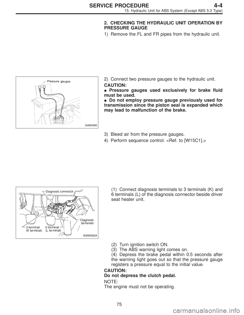
2) Connect two pressure gauges to the hydraulic unit.
CAUTION:
�Pressure gauges used exclusively for brake fluid
must be used.
�Do not employ pressure gauge previously used for
transmission since the piston seal is expanded which
may lead to malfunction of the brake.
3) Bleed air from the pressure gauges.
4) Perform sequence control.
B4M0082A
(1) Connect diagnosis terminals to 3 terminals (K) and
6 terminals (L) of the diagnosis connector beside driver
seat heater unit.
(2) Turn ignition switch ON.
(3) The ABS warning light comes on.
(4) Depress the brake pedal within 0.5 seconds after
the warning light goes out so that the pressure gauge
registers a pressure equal to the initial value.
CAUTION:
Do not depress the clutch pedal.
NOTE:
The engine must not be operating.
75
4-4SERVICE PROCEDURE
15. Hydraulic Unit for ABS System (Except ABS 5.3 Type)
Page 1284 of 2890
 In the case of AWD vehicles, install a spare fuse with
the FWD connector in the engine compartment to simulate
FWD vehicles.
B4M0082A
2) Con")
G4M0462
3. CHECKING THE HYDRAULIC UNIT WITH BRAKE
TESTER
1) In the case of AWD vehicles, install a spare fuse with
the FWD connector in the engine compartment to simulate
FWD vehicles.
B4M0082A
2) Connect diagnosis terminals to 3 terminals (K) and 6
terminals (L) of the diagnosis connector beside driver seat
heater unit.
G4M0464
3) Set the front wheels or rear wheels on the brake tester
and set the select lever’s position at“neutral”.
4) Operate the brake tester.
5) Perform sequence control.
(1) Turn ignition switch ON.
(2) The ABS warning light comes on.
(3) Depress the brake pedal within 0.5 seconds after
the warning light goes out so that the brake tester reg-
isters a pressure equal to the initial value.
CAUTION:
Do not depress the clutch pedal.
NOTE:
The engine must not be operating.
6) Hydraulic unit begins to work; and check the following
working sequence.
(1) The left front wheel performs decompression,
holding, and compression in sequence, and subse-
quently the right front wheel repeats the cycle.
(2) Simultaneously both right and left rear wheel per-
form decompression, holding, and compression in
sequence.
77
4-4SERVICE PROCEDURE
15. Hydraulic Unit for ABS System (Except ABS 5.3 Type)
Page 1297 of 2890
 Operate FRO (Front Right Outlet) valve and RLO
(Rear Left Outlet) valve to bleed air from hydraulic unit
outlet circuit.
(1) Press TCS OFF switch while depressing brake
pedal.
(2) Make sure ABS wa")
11) Operate FRO (Front Right Outlet) valve and RLO
(Rear Left Outlet) valve to bleed air from hydraulic unit
outlet circuit.
(1) Press TCS OFF switch while depressing brake
pedal.
(2) Make sure ABS warning light illuminates.
(3) Repeatedly depress and release brake pedal 10
times or more while pressing TCS OFF switch.
NOTE:
�Air comes out from reservoir tank.
12) Operate FLO (Front Left Outlet) valve and RRO (Rear
Right Outlet) valve to bleed air from hydraulic unit outlet
circuit.
(1) Press TCS OFF switch while depressing brake
pedal.
(2) Make sure TCS warning light illuminates.
(3) Repeatedly depress and release brake pedal 10
times or more while pressing TCS OFF switch.
NOTE:
�Air comes out from reservoir tank.
�The operations in steps 11) and 12) above can be
switched with each other by operating brake pedal (stop
light switch) while pressing TCS OFF switch.
�Repeat procedures 11) and 12) until air no longer comes
out of reservoir tank.
13) Perform these steps for the brakes connecting to the
secondary chamber of master cylinder, first, and then for
the ones connecting to primary chamber. With all proce-
dures completed, fully depress the brake pedal and keep
it in that position for approximately 20 seconds to make
sure that there is no leak evident in the entire system.
14) Turn ignition switch OFF.
15) Perform TCS sequence control.
[W20F0].>
88
4-4SERVICE PROCEDURE
19. Air Bleeding (With TCS model)
Page 1298 of 2890
 Check the pedal stroke.
While the engine is idling, depress the brake pedal with a
490 N (50 kg, 110 lb) load and measure the distance
between the brake pedal and steering wheel. With the")
G4M0436
16) Check the pedal stroke.
While the engine is idling, depress the brake pedal with a
490 N (50 kg, 110 lb) load and measure the distance
between the brake pedal and steering wheel. With the
brake pedal released, measure the distance between the
pedal and steering wheel again. The difference between
the two measurements must be less than specified.
Specified pedal stroke:
With TCS
95 mm (3.74 in)
When depressing brake pedal with a 490 N (50 kg,
110 lb) load.
If the distance is more than specifications, there is a
possibility that air is in the brake line. Bleed air from the
brake line.
17) Turn ignition switch OFF.
18) Disconnect select monitor or diagnosis terminal.
19) Add brake fluid to the required level (MAX. level) of
reserve tank.
20) As a final step, test run the vehicle at low speed and
apply brakes relatively hard 2 to 3 times to ensure that
brakes provide normal braking action on all four wheels
without dragging and uneven braking.
2. CONDITIONS FOR AIR BLEEDING CONTROL
Stop light
switchTCS OFF
switchPump
motorTCS
valveFRO
RLOFLO
RROTCS
operating
indicator
lightABS
warning
lightTCS
warning
light
Air
bleeding
control is
operating.OFF ON ON Close Close Close ON ON ON
ON ON OFF Open Open Close ON ON OFF
ON ON OFF Open Close Open ON OFF ON
ON or OFF OFF OFF Open Close Close ON OFF OFF
Stops tem-
porarily.*——OFF Open Close Close OFF OFF OFF
Prohibited.——OFF Open Close Close OFF ON ON
*: When brake fluid level switch detects brake fluid in LOW level, control operation stops temporarily. After refilling brake fluid, operation
re-starts.
89
4-4SERVICE PROCEDURE
19. Air Bleeding (With TCS model)
Page 1299 of 2890

3. CONDITIONS FOR COMPLETION OF AIR
BLEEDING CONTROL
When any of the following conditions occurs, ABS and TCS
warning lights illuminate. Air bleeding control stops, while
the ABS and TCS function will then stop. The brake sys-
tem functions as a conventional brake system.
1) When the speed of at least one wheel reaches 10 km/h
(6 MPH).
2) When terminal No. 4 is separated from diagnosis termi-
nal. (When select monitor is not used.)
3) When pump motor remains ON for two minutes.
4) When TCS valve remains open for two minutes.
5) When outlet valve remains closed for two minutes.
6) When malfunction is detected.
NOTE:
When a malfunction is detected the air bleeding operation
stops and the trouble codes are stored in memory.
B4M0082C
C: AIR BLEEDING CONTROL WITH
DIAGNOSIS CONNECTOR
1) Connect diagnosis terminals to terminal No. 4 of the
diagnosis connector beside driver’s seat heater unit.
B4M0621A
2) Start the engine while pushing TCS OFF switch.
NOTE:
Keep the TCS OFF switch depressed even after the engine
has started.
3) After ABS and TCS warning lights go out, depress
brake pedal within 0.5 seconds.
4) After ensuring TCS ON indicator illuminates, release
TCS OFF switch and brake pedal.
5) Air bleeding control operation starts.
90
4-4SERVICE PROCEDURE
19. Air Bleeding (With TCS model)
Page 1306 of 2890
 Under the ABS sequence control, after the hydraulic
unit solenoid valve is driven, the operation of the hydraulic
unit can be checked by means of the brake tester or pres-
s")
D: ABS SEQUENCE CONTROL
1) Under the ABS sequence control, after the hydraulic
unit solenoid valve is driven, the operation of the hydraulic
unit can be checked by means of the brake tester or pres-
sure gauge.
2) ABS sequence control can be started by diagnosis con-
nector or select monitor.
B4M0082C
1. OPERATIONAL GUIDELINES OF THE ABS
SEQUENCE CONTROL WITH DIAGNOSIS
CONNECTOR
1) Connect diagnosis terminals to terminal No. 4 of the
diagnosis connector beside driver’s seat heater unit.
2) Ignition switch is turned to ON.
3) Make sure only the start code (code 11) is shown in
normal condition.
NOTE:
When trouble codes are stored in memory, repair the faulty
parts.
4) Set the speed of all wheels at 10 km/h (6 MPH) or less.
5) Turn ignition switch OFF.
6) Within 0.5 seconds after the ABS and TCS warning
lights go out, depress the brake pedal and hold it immedi-
ately after engine starts.
NOTE:
�When the ignition switch is set to on, the brake pedal
must not be depressed.
�Engine must operate.
�If brake pedal is not depressed within 0.5 seconds after
ABS and TCS warning lights go out, the trouble code mode
comes on.
7) After completion of ABS sequence control, turn ignition
switch OFF.
2. OPERATIONAL GUIDELINES OF THE ABS
SEQUENCE CONTROL WITH SELECT MONITOR
1) Connect select monitor to data link connector beside
driver’s seat heater unit.
2) Engine starts.
3) Put select monitor to TCS mode.
4) put select monitor to FBI mode. Make sure code 11 is
indicated.
NOTE:
When trouble codes are stored in memory, repair the faulty
parts.
97
4-4SERVICE PROCEDURE
20. Hydraulic Unit for ABS/TCS System
Page 1308 of 2890
3. CONDITIONS FOR COMPLETION OF ABS
SEQUENCE CONTROL
When the following conditions develop, the ABS sequence
control stops and ABS and TCS warning lights come on
while the ABS and TCS function will then stop. The brake
system functions as a conventional brake system.
1) When the speed of at least one wheel reaches 10 km/h
(6 MPH).
2) When terminal No.4 is separated from ground. (When
select monitor is not used.)
3) When the brake pedal is released during sequence con-
trol and the braking lamp switch is set to off.
4) After completion of the sequence control.
5) When malfunction is detected.
NOTE:
When malfunction has been detected and the ABS
sequence control operation has stopped, the trouble codes
are stored in memory.
99
4-4SERVICE PROCEDURE
20. Hydraulic Unit for ABS/TCS System
Page 1312 of 2890
 Under the TCS sequence control, after the hydraulic
unit solenoid valve is driven, the operation of the hydraulic
unit can be checked by means of the brake tester or pres-
s")
F: TCS SEQUENCE CONTROL
1) Under the TCS sequence control, after the hydraulic
unit solenoid valve is driven, the operation of the hydraulic
unit can be checked by means of the brake tester or pres-
sure gauge.
2) TCS sequence control can be started by diagnosis con-
nector or select monitor.
B4M0082C
1. OPERATIONAL GUIDELINES OF THE TCS
SEQUENCE CONTROL WITH DIAGNOSIS
CONNECTOR
1) Connect diagnosis terminals to terminal No. 4 of the
diagnosis connector beside driver seat heater unit.
2) Ignition switch is turned to ON.
3) Make sure only the start code (code 11) is shown in
normal condition.
NOTE:
When trouble codes are stored in memory, repair the faulty
parts.
4) Set the speed of all wheels at 10 km/h (6 MPH) or less.
5) Turn ignition switch OFF.
6) Start engine, and within 0.5 seconds after the ABS
warning light and TCS warning light go out, press TCS OFF
switch. Within 1.0 second thereafter, release and press the
switch again. Then, keep the switch pressed.
NOTE:
�When the TCS sequence control is set to on, the brake
pedal must not be depressed.
�Engine must operate.
�When TCS OFF switch is not depressed within 0.5 sec-
onds after ABS and TCS warning lights turn off, the trouble
code mode comes on.
7) After completion of TCS sequence control, turn ignition
switch OFF.
103
4-4SERVICE PROCEDURE
20. Hydraulic Unit for ABS/TCS System