Page 1674 of 2890
6. Turn Signal and Hazard Warning
Light
A: REMOVAL AND INSTALLATION
1. FRONT TURN SIGNAL LIGHT
Refer to 6-2 [W4B2] as for removal and installation of front
turn signal light.
NOTE:
The front turn signal light is united with headlight assem-
bly.
2. REAR COMBINATION LIGHT
Refer to 6-2 [W5A1] as for removal and installation of rear
combination light.
3. COMBINATION SWITCH
Refer to 6-2 [W4B3] as for removal and installation of com-
bination switch.
B6M0063
4. HAZARD SWITCH
1) Remove center panel from instrument panel.
5-4 [W1A0].>
2) Disconnect connector of hazard switch from body har-
ness.
3) Remove hazard switch from center panel.
B6M0343A
5. TURN SIGNAL AND HAZARD UNIT
1) Remove instrument panel lower cover.
2) Remove engine hood opener lever bracket.
3) Disconnect connector of turn signal and hazard unit.
4) Remove screw, and then remove turn signal and haz-
ard unit from bracket.
18
6-2SERVICE PROCEDURE
6. Turn Signal and Hazard Warning Light
Page 1675 of 2890
B: DISASSEMBLY AND ASSEMBLY
1. COMBINATION SWITCH
Refer to 6-2 [W4C1] as for disassembly and assembly of
combination switch.
C: INSPECTION
1. COMBINATION SWITCH (ON-CAR)
1) Remove instrument panel lower cover.
2) Remove lower column cover.
B6M0238
3) Unfasten holddown clip which secures harness, and
disconnect connectors from body harness.
4) Move combination switch to respective positions and
check continuity between terminals as indicated in table
below:
Turn signal switch
Terminal
Switch positiona-5 a-7 a-6
TurnL⋅L′��
*xx
N
*xx
R⋅R′��
B6M0344
2. HAZARD SWITCH
Move hazard switch to each position and check continuity
between terminals as indicated in table below:
73910561 2
ON��
�����
OFF����
19
6-2SERVICE PROCEDURE
6. Turn Signal and Hazard Warning Light
Page 1695 of 2890
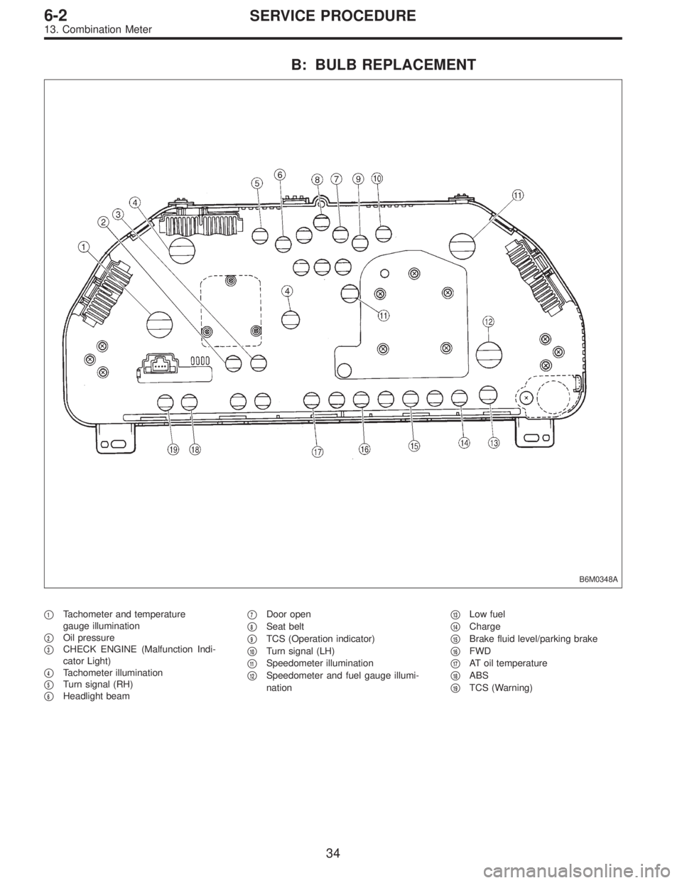
B: BULB REPLACEMENT
B6M0348A
�1Tachometer and temperature
gauge illumination
�
2Oil pressure
�
3CHECK ENGINE (Malfunction Indi-
cator Light)
�
4Tachometer illumination
�
5Turn signal (RH)
�
6Headlight beam�
7Door open
�
8Seat belt
�
9TCS (Operation indicator)
�
10Turn signal (LH)
�
11Speedometer illumination
�
12Speedometer and fuel gauge illumi-
nation�
13Low fuel
�
14Charge
�
15Brake fluid level/parking brake
�
16FWD
�
17AT oil temperature
�
18ABS
�
19TCS (Warning)
34
6-2SERVICE PROCEDURE
13. Combination Meter
Page 1829 of 2890
 Turn ignition switch to ON (engine OFF) and Subaru
select monitor switch to ON.
7) Start the engine.
NOTE:
�Ensure the selector lever is placed in the“P”position
before starting. (AT ve")
OBD0060
6) Turn ignition switch to ON (engine OFF) and Subaru
select monitor switch to ON.
7) Start the engine.
NOTE:
�Ensure the selector lever is placed in the“P”position
before starting. (AT vehicles)
�Depress clutch pedal when starting the engine. (MT
vehicles)
8) Using the selector lever or shift lever, turn the“P”posi-
tion switch and the“N”position switch to ON.
9) Depress the brake pedal to turn the brake switch ON.
(AT vehicles)
10) Keep engine speed in the 2,500—3,000 rpm range
for 40 seconds.
NOTE:
On models without tachometer, use the Subaru select
monitor or tachometer (Secondary pickup type).
11) Place the selector lever or shift lever in the“D”posi-
tion (AT vehicles) or“1st”gear (MT vehicles) and drive the
vehicle at 5 to 10 km/h (3 to 6 MPH).
NOTE:
�On AWD vehicles, release the parking brake.
�The speed difference between front and rear wheels
may light either the ABS or the ABS/TCS warning light, but
this indicates no malfunctions. When engine control diag-
nosis is finished, perform the ABS or the ABS/TCS memory
clearance procedure of self-diagnosis system.
4-4b [T6D2] or [T9K0], 4-4c [T6D2] or [T9J0].>
OBD0005B
3. OBD-II GENERAL SCAN TOOL
After performing diagnostics and clearing the memory,
check for any remaining unresolved trouble data:
1) Connect test mode connector at the lower side of the
instrument panel (on the driver’s side), to the side of the
center console box.
OBD0006C
2) Open the cover and connect the OBD-II general scan
tool to its data link connector in the lower portion of the
instrument panel (on the driver’s side), to the lower cover.
CAUTION:
Do not connect the scan tools except for Subaru select
monitor and OBD-II general scan tool.
61
2-7ON-BOARD DIAGNOSTICS II SYSTEM
3. Diagnosis System
Page 1830 of 2890
 Start the engine.
NOTE:
�Ensure the selector lever is placed in the“P”position
before starting. (AT vehicles)
�Depress clutch pedal when starting the engine. (MT
vehicles)
4) Using the selector")
3) Start the engine.
NOTE:
�Ensure the selector lever is placed in the“P”position
before starting. (AT vehicles)
�Depress clutch pedal when starting the engine. (MT
vehicles)
4) Using the selector lever or shift lever, turn the“P”posi-
tion switch and the“N”position switch to ON.
5) Depress the brake pedal to turn the brake switch ON.
(AT vehicles)
6) Keep engine speed in the 2,500—3,000 rpm range for
40 seconds.
NOTE:
On models without tachometer, use the Subaru select
monitor or tachometer (Secondary pickup type).
7) Place the selector lever or shift lever in the“D”position
(AT vehicles) or“1st”gear (MT vehicles) and drive the
vehicle at 5 to 10 km/h (3 to 6 MPH).
NOTE:
�On AWD vehicles, release the parking brake.
�The speed difference between front and rear wheels
may light either the ABS or the ABS/TCS warning light, but
this indicates no malfunctions. When engine control diag-
nosis is finished, perform the ABS or the ABS/TCS memory
clearance procedure of self-diagnosis system.
4-4b [T6D2] or [T9K0], 4-4c [T6D2] or [T9J0].>
8) Using the OBD-II general scan tool, check for diagnos-
tic trouble code(s) and record the result(s).
NOTE:
�For detailed operation procedures, refer to the OBD-II
General Scan Tool Instruction Manual.
�For details concerning diagnostic trouble codes, refer to
the DIAGNOSTIC TROUBLE CODE (DTC) LIST, 2-7
[T10A0].
H2M1149
4. READ DIAGNOSTIC TROUBLE CODE (DTC)
SHOWN ON DISPLAY. (MODE FB0
MODE>)
Using Subaru select monitor, check for diagnostic trouble
code(s) and record the result(s).
1) Select engine mode using function key.
Press the function key [0].
62
2-7ON-BOARD DIAGNOSTICS II SYSTEM
3. Diagnosis System
Page 1846 of 2890
 Other warning lights or indicators turn on.�Ye s /�No
��
1Low fuel warning light
��
2Charge indicator light
��
3AT diagnosti")
Check the following items about the vehicle’s state when
MIL turns on.
a) Other warning lights or indicators turn on.�Ye s /�No
��
1Low fuel warning light
��
2Charge indicator light
��
3AT diagnostics indicator light
��
4ABS warning light
��
5TCS warning light
��
6Engine oil pressure warning light
b) Fuel level
�Lack of gasoline:�Ye s /�No
�Indicator position of fuel gauge:
c) Intentional connecting or disconnecting of harness connectors or spark plug cords:�Ye s /�No
�What:
d) Intentional connecting or disconnecting of hoses:�Ye s /�No
�What:
e) Installing of parts other than genuine parts�Ye s /�No
�What:
�Where:
f) Occurrence of noise�Ye s /�No
�From where:
�What kind:
g) Occurrence of smell�Ye s /�No
�From where:
�What kind:
h) Intrusion of water into engine compartment or passenger compartment�Ye s /�No
i) Troubles occurred
��
1Engine does not start.
��
2Engine stalls during idling.
��
3Engine stalls while driving.
��
4Engine speed decreases.
��
5Engine speed does not decrease.
��
6Rough idling
��
7Poor acceleration
��
8Back fire
��
9After fire
��
10No shift
��
11Excessive shift shock
NOTE: Use copies of this page for interviewing customers.
78
2-7ON-BOARD DIAGNOSTICS II SYSTEM
6. Basic Diagnostics Procedure
Page 2142 of 2890
 Check that selector lever does not move from“N”to“R”
without pushing the bu")
G3M0717
3. OPERATION OF SHIFT SELECTOR LEVER
WARNING:
Stop the engine while checking operation of selector
lever.
1) Check that selector lever does not move from“N”to“R”
without pushing the button.
2) Check that selector lever does not move from“R”to“P”
without pushing the button.
3) Check that selector lever does not move from“P”to“R”
without pushing the button.
4) Check that selector lever does not move from“3”to“2”
without pushing the button.
3. Electrical Components Location
1. SENSOR AND CONTROL MODULE
B3M0178B
�1Throttle position sensor
�
2Dropping resistor
�
3Vehicle speed sensor 2
�
4Inhibitor switch
�
5ECM
�
6Vehicle speed sensor 1 (AWD)
�
7Vehicle speed sensor 1 (FWD)
�
8TCM�
9Data link connector (for Subaru select monitor only)
�
10Data link connector (for Subaru select monitor and OBD-II
general scan tool)
�
11Diagnosis connector
�
12Diagnosis terminal
�
13AT OIL TEMP indicator light
(AT diagnostic indicator light)
3
3-2AUTOMATIC TRANSMISSION AND DIFFERENTIAL
2. Pre-inspection - 3. Electrical Components Location
Page 2143 of 2890
 Check that selector lever does not move from“N”to“R”
without pushing the bu")
G3M0717
3. OPERATION OF SHIFT SELECTOR LEVER
WARNING:
Stop the engine while checking operation of selector
lever.
1) Check that selector lever does not move from“N”to“R”
without pushing the button.
2) Check that selector lever does not move from“R”to“P”
without pushing the button.
3) Check that selector lever does not move from“P”to“R”
without pushing the button.
4) Check that selector lever does not move from“3”to“2”
without pushing the button.
3. Electrical Components Location
1. SENSOR AND CONTROL MODULE
B3M0178B
�1Throttle position sensor
�
2Dropping resistor
�
3Vehicle speed sensor 2
�
4Inhibitor switch
�
5ECM
�
6Vehicle speed sensor 1 (AWD)
�
7Vehicle speed sensor 1 (FWD)
�
8TCM�
9Data link connector (for Subaru select monitor only)
�
10Data link connector (for Subaru select monitor and OBD-II
general scan tool)
�
11Diagnosis connector
�
12Diagnosis terminal
�
13AT OIL TEMP indicator light
(AT diagnostic indicator light)
3
3-2AUTOMATIC TRANSMISSION AND DIFFERENTIAL
2. Pre-inspection - 3. Electrical Components Location
![SUBARU LEGACY 1996 Service Repair Manual 6. Turn Signal and Hazard Warning
Light
A: REMOVAL AND INSTALLATION
1. FRONT TURN SIGNAL LIGHT
Refer to 6-2 [W4B2] as for removal and installation of front
turn signal light.
NOTE:
The front turn sign](/manual-img/17/57433/w960_57433-1673.png "SUBARU LEGACY 1996 Service Repair Manual 6. Turn Signal and Hazard Warning
Light
A: REMOVAL AND INSTALLATION
1. FRONT TURN SIGNAL LIGHT
Refer to 6-2 [W4B2] as for removal and installation of front
turn signal light.
NOTE:
The front turn sign")
![SUBARU LEGACY 1996 Service Repair Manual B: DISASSEMBLY AND ASSEMBLY
1. COMBINATION SWITCH
Refer to 6-2 [W4C1] as for disassembly and assembly of
combination switch.
C: INSPECTION
1. COMBINATION SWITCH (ON-CAR)
1) Remove instrument panel low](/manual-img/17/57433/w960_57433-1674.png "SUBARU LEGACY 1996 Service Repair Manual B: DISASSEMBLY AND ASSEMBLY
1. COMBINATION SWITCH
Refer to 6-2 [W4C1] as for disassembly and assembly of
combination switch.
C: INSPECTION
1. COMBINATION SWITCH (ON-CAR)
1) Remove instrument panel low")