Page 2161 of 2890
 Connect connectors to TCM and transmission.
2) Lift-up the vehicle or set the vehicle on free roller.
CAUTION:
On AWD models, raise all wheels off")
OBD0607A
4. CHECK OUTPUT SIGNAL EMITTED FROM TCM.
1) Connect connectors to TCM and transmission.
2) Lift-up the vehicle or set the vehicle on free roller.
CAUTION:
On AWD models, raise all wheels off floor.
3) Start and warm-up the engine and transmission.
4) Push the TCS OFF switch to ON. (With TCS models)
5) Move selector lever to“D”and slowly increase vehicle
speed to 75 km/h (47 MPH).
6) Measure voltage between TCM connector terminals.
Connector & terminal / Specified voltage:
(B55) No. 5—No. 10 / 8.5 V, or more (when
wheels are locked-up.)
OBD0607A
7) Return the engine to idling speed and move selector
lever to“N”.
8) Measure voltage between TCM connector terminals.
Connector & terminal / Specified voltage:
(B55) No. 5—No. 10 / 0.5 V, or less
NOTE:
The speed difference between front and rear wheels may
light either the ABS or the ABS/TCS warning light, but this
indicates no malfunctions. When AT control diagnosis is
finished, perform the ABS or the ABS/TCS memory clear-
ance procedure of self-diagnosis system.
OBD0145A
�Using Subaru select monitor:
(1) Connect connectors to TCM and transmission.
(2) Lift-up the vehicle or set the vehicle on free roller.
CAUTION:
On AWD models, raise all wheels off floor.
(3) Turn ignition switch to OFF.
(4) Connect the Subaru select monitor to data link con-
nector.
(5) Turn ignition switch to ON and Subaru select moni-
tor switch to ON.
21
3-2AUTOMATIC TRANSMISSION AND DIFFERENTIAL
7. Diagnostic Chart with Trouble Code
Page 2162 of 2890
OBD0417
(6) Start and warm-up the engine and transmission.
(7) Push the TCS OFF switch to ON. (With TCS mod-
els)
(8) Designate mode using function key.
Function mode: F12
(9) Move selector lever to“D”and slowly increase
vehicle speed to 75 km/h (47 MPH).
(10) Read data on Subaru select monitor.
SPECIFIED DATA:
�95% (Wheel locked-up)
�5% (Released)
NOTE:
The speed difference between front and rear wheels may
light either the ABS or the ABS/TCS warning light, but this
indicates no malfunctions. When AT control diagnosis is
finished, perform the ABS or the ABS/TCS memory clear-
ance procedure of self-diagnosis system.
22
3-2AUTOMATIC TRANSMISSION AND DIFFERENTIAL
7. Diagnostic Chart with Trouble Code
Page 2164 of 2890
 Measure resistance of harness connector between
TCM and body to make sure that circuit does not short.
Connector & terminal / Specified resistance:
(B55) No. 15—Body/1MΩ, or more
(B55)")
OBD0455A
4) Measure resistance of harness connector between
TCM and body to make sure that circuit does not short.
Connector & terminal / Specified resistance:
(B55) No. 15—Body/1MΩ, or more
(B55) No. 10—Body/1MΩ, or more
G3M0109
2. CHECK SHIFT SOLENOID 3’s GROUND LINE.
Measure resistance between transmission connector
receptacle and transmission case.
Connector & terminal / Specified resistance:
(T4) No. 4—Transmission / 1Ω, or less
G3M0117
3. CHECK SHIFT SOLENOID 3.
Measure resistance between transmission connector
receptacle’s terminals.
Connector & terminal / Specified resistance:
(T4) No. 1—No.4/20—32Ω
B3M0381A
4. CHECK OUTPUT SIGNAL EMITTED FROM TCM.
1) Connect connectors to TCM and transmission.
2) Lift-up or raise the vehicle and support with safety
stands.
CAUTION:
On AWD models, raise all wheels off ground.
3) Start and warm-up the engine and transmission.
4) Idle the engine.
5) Move selector lever to“D”.
6) Measure voltage between TCM connector terminals.
Connector & terminal / Specified voltage:
(B55) No. 15—No. 10 / 9 V, or more
NOTE:
The speed difference between front and rear wheels may
light either the ABS or the ABS/TCS warning light, but this
indicates no malfunctions. When AT control diagnosis is
finished, perform the ABS or the ABS/TCS memory clear-
ance procedure of self-diagnosis system.
24
3-2AUTOMATIC TRANSMISSION AND DIFFERENTIAL
7. Diagnostic Chart with Trouble Code
Page 2166 of 2890
 Measure resistance of harness connector between
TCM and body to make sure that circuit does not short.
Connector & terminal / Specified resistance:
(B55) No. 13—Body/1MΩ, or more
(B55)")
OBD0447A
4) Measure resistance of harness connector between
TCM and body to make sure that circuit does not short.
Connector & terminal / Specified resistance:
(B55) No. 13—Body/1MΩ, or more
(B55) No. 10—Body/1MΩ, or more
G3M0109
2. CHECK SHIFT SOLENOID 2’s GROUND LINE.
Measure resistance between transmission connector
receptacle and transmission case.
Connector & terminal / Specified resistance:
(T4) No. 4—Transmission / 1Ω, or less
G3M0120
3. CHECK SHIFT SOLENOID 2.
Measure resistance between transmission connector
receptacle’s terminals.
Connector & terminal / Specified resistance:
(T4) No. 2—No.4/20—32Ω
OBD0445A
4. CHECK OUTPUT SIGNAL EMITTED FROM TCM.
1) Connect connectors to TCM and transmission.
2) Lift-up or raise the vehicle and support with safety
stands.
CAUTION:
On AWD models, raise all wheels off ground.
3) Start and warm-up the engine and transmission.
4) Idle the engine.
5) Move selector lever to“D”.
6) Measure voltage between TCM connector terminals.
Connector & terminal / Specified voltage:
(B55) No. 13—No. 10 / 9 V, or more
NOTE:
The speed difference between front and rear wheels may
light either the ABS or the ABS/TCS warning light, but this
indicates no malfunctions. When AT control diagnosis is
finished, perform the ABS or the ABS/TCS memory clear-
ance procedure of self-diagnosis system.
26
3-2AUTOMATIC TRANSMISSION AND DIFFERENTIAL
7. Diagnostic Chart with Trouble Code
Page 2168 of 2890
 Measure resistance of harness connector between
TCM and body to make sure that circuit does not short.
Connector & terminal / Specified resistance:
(B55) No. 14—Body/1MΩ, or more
(B55)")
OBD0439A
4) Measure resistance of harness connector between
TCM and body to make sure that circuit does not short.
Connector & terminal / Specified resistance:
(B55) No. 14—Body/1MΩ, or more
(B55) No. 10—Body/1MΩ, or more
G3M0109
2. CHECK SHIFT SOLENOID 1’s GROUND LINE.
Measure resistance between transmission connector
receptacle and transmission case.
Connector & terminal / Specified resistance:
(T4) No. 4—Transmission / 1Ω, or less
G3M0123
3. CHECK SHIFT SOLENOID 1.
Measure resistance between transmission connector
receptacle’s terminals.
Connector & terminal / Specified resistance:
(T4) No. 3—No.4/20—32Ω
OBD0437A
4. CHECK OUTPUT SIGNAL EMITTED FROM TCM.
1) Connect connectors to TCM and transmission.
2) Lift-up or raise the vehicle and support with safety
stands.
CAUTION:
On AWD models, raise all wheels off ground.
3) Start and warm-up the engine and transmission.
4) Idle the engine.
5) Move selector lever to“D”.
6) Measure voltage between TCM connector terminals.
Connector & terminal / Specified voltage:
(B55) No. 14—No. 10 / 9 V, or more
NOTE:
The speed difference between front and rear wheels may
light either the ABS or the ABS/TCS warning light, but this
indicates no malfunctions. When AT control diagnosis is
finished, perform the ABS or the ABS/TCS memory clear-
ance procedure of self-diagnosis system.
28
3-2AUTOMATIC TRANSMISSION AND DIFFERENTIAL
7. Diagnostic Chart with Trouble Code
Page 2185 of 2890
 Connect connectors to TCM and transmission.
2) Lift-up or raise the vehicle and place safety stands.
CAUTION:
On AWD models, raise all wheels off floor.
3) P")
OBD0396A
3. CHECK INPUT SIGNAL FOR TCM.
1) Connect connectors to TCM and transmission.
2) Lift-up or raise the vehicle and place safety stands.
CAUTION:
On AWD models, raise all wheels off floor.
3) Push the TCS OFF switch to ON. (With TCS models)
4) Start the engine and set vehicle in 20 km/h (12 MPH)
condition.
5) Measure voltage between TCM connector terminals.
Connector & terminal / Specified voltage:
(B54) No. 12—No. 7 / AC 1 V, or more
NOTE:
The speed difference between front and rear wheels may
light either the ABS or the ABS/TCS warning light, but this
indicates no malfunctions. When AT control diagnosis is
finished, perform the ABS or the ABS/TCS memory clear-
ance procedure of self-diagnosis system.
OBD0145A
B3M0413
OBD0399
�Using Subaru select monitor:
(1) Connect connectors to TCM and transmission.
(2) Turn ignition switch to OFF.
(3) Connect the Subaru select monitor to data link con-
nector.
(4) Lift-up or raise the vehicle and place safety stands.
CAUTION:
On AWD models, raise all wheels off floor.
(5) Turn ignition switch to ON and Subaru select moni-
tor switch to ON.
(6) Push the TCS OFF switch to ON. (With TCS mod-
els)
(7) Start the engine and operate at constant speed.
(8) Read data on Subaru select monitor.
(9) Designate mode using function key.
Function mode: F02 or F03
SPECIFIED DATA:
F02: Compare speedometer with monitor indica-
tions.
F03: Compare speedometer with monitor indica-
tions.
�F02: Vehicle speed is indicated in“m/h”.
�F03: Vehicle speed is indicated in“km/h”.
NOTE:
The speed difference between front and rear wheels may
light either the ABS or the ABS/TCS warning light, but this
indicates no malfunctions. When AT control diagnosis is
finished, perform the ABS or the ABS/TCS memory clear-
ance procedure of self-diagnosis system.
45
3-2AUTOMATIC TRANSMISSION AND DIFFERENTIAL
7. Diagnostic Chart with Trouble Code
Page 2186 of 2890
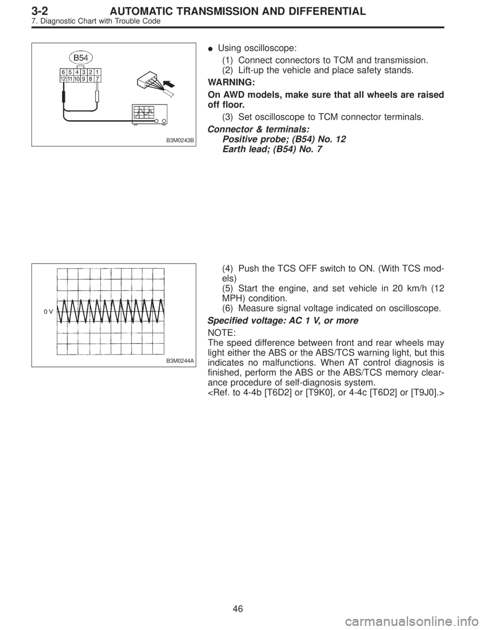
B3M0243B
�Using oscilloscope:
(1) Connect connectors to TCM and transmission.
(2) Lift-up the vehicle and place safety stands.
WARNING:
On AWD models, make sure that all wheels are raised
off floor.
(3) Set oscilloscope to TCM connector terminals.
Connector & terminals:
Positive probe; (B54) No. 12
Earth lead; (B54) No. 7
B3M0244A
(4) Push the TCS OFF switch to ON. (With TCS mod-
els)
(5) Start the engine, and set vehicle in 20 km/h (12
MPH) condition.
(6) Measure signal voltage indicated on oscilloscope.
Specified voltage: AC 1 V, or more
NOTE:
The speed difference between front and rear wheels may
light either the ABS or the ABS/TCS warning light, but this
indicates no malfunctions. When AT control diagnosis is
finished, perform the ABS or the ABS/TCS memory clear-
ance procedure of self-diagnosis system.
46
3-2AUTOMATIC TRANSMISSION AND DIFFERENTIAL
7. Diagnostic Chart with Trouble Code
Page 2189 of 2890
 Install combination meter.
2) Connect connector to TCM.
3) Lift-up the vehicle and place safety stand.
CAUTION:
On AWD models, raise all wheels off floor.
4")
B3M0289
3. CHECK VEHICLE SPEED SENSOR 2.
1) Install combination meter.
2) Connect connector to TCM.
3) Lift-up the vehicle and place safety stand.
CAUTION:
On AWD models, raise all wheels off floor.
4) Disconnect connector from vehicle speed sensor 2.
5) Measure resistance between terminals of vehicle speed
sensor 2.
Terminals / Specified resistance:
(B17) No. 1—No. 2 / 350—450Ω
No. 1—Body/1MΩ, or more
No. 2—Body/1MΩ, or more
B3M0256
6) Push the TCS OFF switch to ON. (With TCS models)
7) Start the engine and set vehicle in 20 km/h (12 MPH)
condition.
8) Measure output signal of vehicle speed sensor 2.
WARNING:
Be careful not to be caught up by the running wheels.
9) Using a voltage meter; measure voltage between termi-
nals of vehicle speed sensor 2.
Terminals / Specified voltage:
(B17) No. 1—No. 2 / AC 2 V, or more
NOTE:
The speed difference between front and rear wheels may
light either the ABS or the ABS/TCS warning light, but this
indicates no malfunctions. When AT control diagnosis is
finished, perform the ABS or the ABS/TCS memory clear-
ance procedure of self-diagnosis system.
49
3-2AUTOMATIC TRANSMISSION AND DIFFERENTIAL
7. Diagnostic Chart with Trouble Code
 Start and warm-up the engine and transmission.
(7) Push the TCS OFF switch to ON. (With TCS mod-
els)
(8) Designate mode using function key.
Function mode: F12
(9) Move selector lever to�")