Page 2222 of 2890
Trouble codeDiagnostic items
Detection timingIndicator
light ON
Parts concerned
At initial checking
Under no control
Under ABS control
Under TCS control
In diagnostic mode
ABS warning light
TCS warning light
TCS OFF indicator light
43 Abnormal EGI communication line
���—�—AET communication line (ABS/TCS C/M)
���—�—
�—�—
����—�—AEB communication line (ABS/TCS C/M)
����—�—
��—�—
����—�—AEC communication line (ABS/TCS C/M)
����—�—
���—�—
—Abnormal EGI communication line
���——�EAM communication line (ABS/TCS C/M)
51 Abnormal valve relay
���—Valve relay (ABS/TCS C/M)
Abnormal valve relay
���� ��—Valve relay (ABS/TCS C/M)
���� ��—
52 Abnormal motor system
��� ��—Motor (ABS/TCS C/M)
Abnormal motor system
�� ��—Motor (ABS/TCS C/M)
Abnormal motor system
���—
11
4-4bBRAKES
5. Control Module I/O Signal
Page 2223 of 2890

Trouble codeDiagnostic items
Detection timingIndicator
light ON
Parts concerned
At initial checking
Under no control
Under ABS control
Under TCS control
In diagnostic mode
ABS warning light
TCS warning light
TCS OFF indicator light
54 Abnormal pedal stroke sensor and stop light switch
��� ��—Pedal stroke sensor (ABS/TCS C/M)
Abnormal pedal stroke sensor and stop light switch
���—Pedal stroke sensor (ABS/TCS C/M)
Abnormal pedal stroke sensor and stop light switch
���—Stop light switch, pedal stroke sensor (ABS/TCS C/M)
Abnormal pedal stroke sensor and stop light switch
���—Pump, pedal stroke sensor (ABS/TCS C/M)
Abnormal stroke sensor and stop light switch
���—�—Stop light switch circuit (ABS/TCS C/M)
57 Abnormal fluid level sensor
���—Fluid level sensor circuit
—Abnormal fluid level sensor
���� ��—Fluid level sensor circuit, reservoir
58 Abnormal pressure switch
����—�—Pressure switch (ABS/TCS C/M)
���—�—Pressure switch, stop light switch (ABS/TCS C/M)
���—�—Pressure switch (ABS/TCS C/M)
12
4-4bBRAKES
5. Control Module I/O Signal
Page 2224 of 2890
6. Diagnostics Chart for On-board
Diagnosis System
A: BASIC DIAGNOSTICS PROCEDURE
TROUBLE OCCURS.
Ask the customer when and how the
trouble occurred using interview
check list.
PRE-INSPECTION
INSPECTION MODE
CALLING UP A TROUBLE CODE.
�No trouble code is readable.
�
Inspection using Diagnostic Chart for
Warning Light Failure.
Record all trouble codes.
Trouble codes
are issued.
�Only the start code is issued.
Inspection using General Diagnostics
Chart
Perform diagnostics in accordance with trouble code.
Trouble code
designated.
�
Repair.�
Clear memory.
INSPECTION MODE
CALLING UP A TROUBLE CODE.
Only the start code is issued.
CONFIRMATION TEST
END
NOTE:
�To check harness for broken wires or short circuits,
shake it while holding it or the connector.
�When TCS warning light illuminates, read and record
trouble code indicated by TCS warning light.
�
�
�
�
�
�
�
�
�
�
�
�
13
4-4bBRAKES
6. Diagnostics Chart for On-board Diagnosis System
Page 2225 of 2890

B: CHECK LIST FOR INTERVIEW
Check the following items about the vehicle’s state.
1. THE STATE OF THE WARNING LIGHTS
a. ABS warning light
�
1Is always on.�2Sometimes comes on.�3Comes on only once.�4Does not come on.
When/how long does it come on?
Ignition key
position�
1Lock�2Acc�3On (before starting engine)�4Start�5On after starting (Engine: run)
�6On after starting (Engine: stop)
Timing�
1Immediately after ignition is on.�2Immediately after ignition starts.
�3When advancing (Speedmiles/h,miles/h)�4While traveling at a constant speed (Speedmiles/h)
�5When decelerating (Speedmiles/h,miles/h)
�6When turning (To right, to left, steering angledeg., steering timesec)
�7When other electrical parts move (Part name:, Operating condition)
�8When moving other electrical parts (Part name:, Operating condition)
b. TCS warning light
�
1Is always on.�2Sometimes comes on.�3Comes on only once.�4Does not come on.
When does it come on?
Ignition key
position�
1Lock�2Acc�3On (before starting engine)�4Start�5On after starting (Engine: run)
�6On after starting (Engine: stop)
Timing�
1Immediately after ignition is on.�2Immediately after ignition starts.
�3When advancing (Speedmiles/h,miles/h)�4While traveling at a constant speed (Speedmiles/h)
�5When decelerating (Speedmiles/h,miles/h)
�6When turning (To right, to left, steering angledeg., steering timesec)
�7When other electrical parts move (Part name:, Operating condition)
�8When moving other electrical parts (Part name:, Operating condition)
c. TCS OFF indicator light
�
1Is always on.�2Sometimes comes on.�3Comes on only once.�4Does not come on.
When/how long does it come on?
Ignition key
position�
1Lock�2Acc�3On (before starting engine)�4Start�5On after starting (Engine: run)
�6On after starting (Engine: stop)
Timing�
1Immediately after ignition is on.�2Immediately after ignition starts.
�3When advancing (Speedmiles/h,miles/h)�4While traveling at a constant speed (Speedmiles/h)
�5When decelerating (Speedmiles/h,miles/h)
�6When turning (To right, to left, steering angledeg., steering timesec)
�7When other electrical parts move (Part name:, Operating condition)
�8When moving other electrical parts (Part name:, Operating condition)
d. TCS operation indicator light
�
1Is always on.�2Sometimes comes on.�3Comes on only once.�4Does not come on.
When does it come on?
Ignition key
position�
1Lock�2Acc�3On (before starting engine)�4Start�5On after starting (Engine: run)
�6On after starting (Engine: stop)
Timing�
1Immediately after ignition is on.�2Immediately after ignition starts.
�3When advancing (Speedmiles/h,miles/h)�4While traveling at a constant speed (Speedmiles/h)
�5When decelerating (Speedmiles/h,miles/h)
�6When turning (To right, to left, steering angledeg., steering timesec)
�7When other electrical parts move (Part name:, Operating condition)
�8When moving other electrical parts (Part name:, Operating condition)
14
4-4bBRAKES
6. Diagnostics Chart for On-board Diagnosis System
Page 2227 of 2890

C: INSPECTION MODE
The on-board diagnosis system is designed to detect prob-
lems while the vehicle is being driven. If a problem is found,
the ABS and TCS warning light will illuminate to inform the
driver of the occurrence of a problem. When the warning
light is on, the ABS/TCS system will be inactive and the
normal braking function will work. It is possible for the most
recent trouble code and history of problem to be stored in
memory until cleared.
B4M0082C
D: TROUBLE CODES
When on-board diagnosis of the ABS/TCS control module
detects a problem, the information will be stored in the EEP
ROM as a trouble code. (Stored codes will stay in memory
until they are cleared.)
1. CALLING UP A TROUBLE CODE
1) Take out diagnosis connector from side of driver’s seat
heater unit.
2) Turn ignition switch OFF.
3) Connect diagnosis connector terminal No. 4 to diagno-
sis terminal.
4) Turn ignition switch ON.
5) TCS warning light is set in the diagnostic mode and
blinks to identify trouble code.
6) After the start code (11) is shown, the trouble codes will
be shown in order of the last information first.
NOTE:
When there are no trouble codes in memory, only the start
code (11) is shown.
B4M0383A
16
4-4bBRAKES
6. Diagnostics Chart for On-board Diagnosis System
Page 2229 of 2890
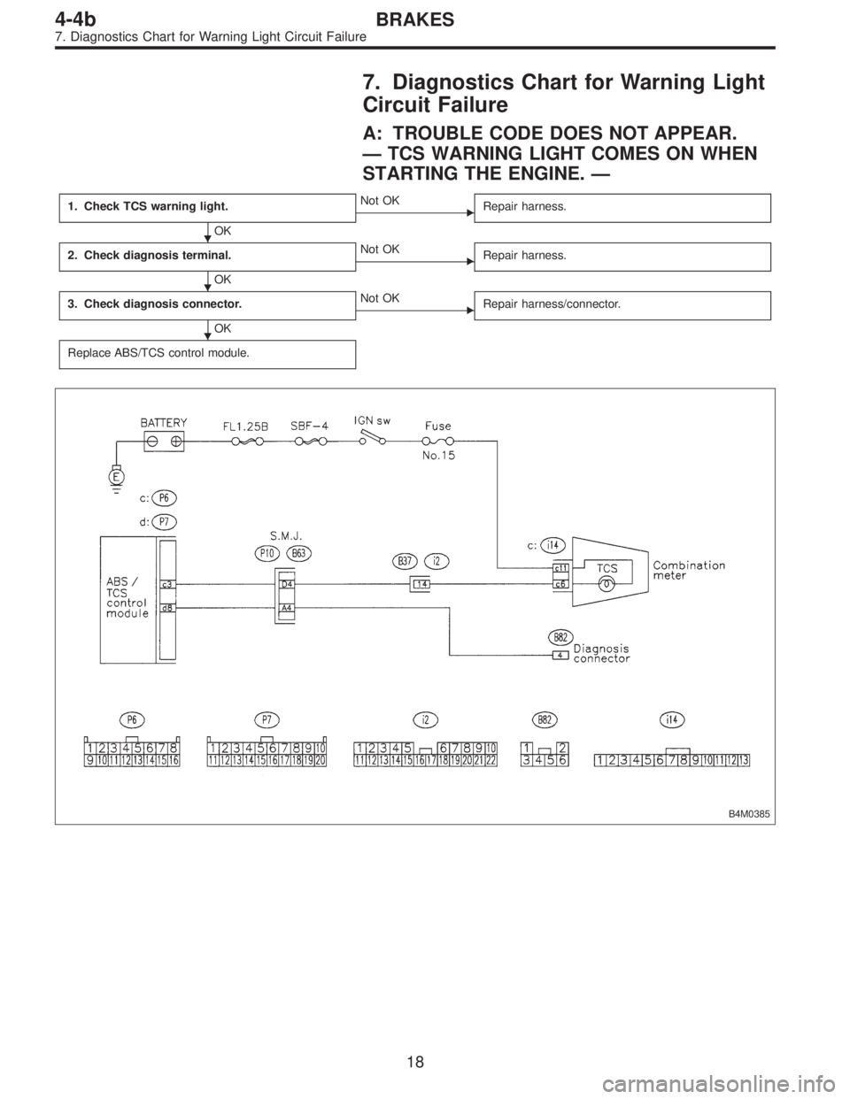
7. Diagnostics Chart for Warning Light
Circuit Failure
A: TROUBLE CODE DOES NOT APPEAR.
—TCS WARNING LIGHT COMES ON WHEN
STARTING THE ENGINE.—
1. Check TCS warning light.
OK
�Not OK
Repair harness.
2. Check diagnosis terminal.
OK
�Not OK
Repair harness.
3. Check diagnosis connector.
OK
�Not OK
Repair harness/connector.
Replace ABS/TCS control module.
B4M0385
�
�
�
18
4-4bBRAKES
7. Diagnostics Chart for Warning Light Circuit Failure
Page 2230 of 2890
B4M0715A
1. CHECK TCS WARNING LIGHT.
1) Turn ignition switch OFF.
2) Disconnect all connectors from ABS/TCS control mod-
ule.
3) Turn ignition switch ON.
4) Measure voltage between ABS/TCS control module
connector and body.
Connector & terminal / Specified voltage:
(P6) No. 3 — body / 10 — 14 V
B4M0387A
2. CHECK DIAGNOSIS TERMINAL.
1) Turn ignition switch OFF.
2) Measure resistance between diagnosis terminal and
body.
Connector/Specified resistance:
B81 — body / 0Ω
B4M0388A
3. CHECK DIAGNOSIS CONNECTOR.
1) Turn ignition switch OFF.
2) Disconnect all connectors from ABS/TCS control mod-
ule.
3) Measure resistance between diagnosis connector and
body.
Connector & terminal / Specified resistance:
(B82) No. 4 — body / 0Ω
19
4-4bBRAKES
7. Diagnostics Chart for Warning Light Circuit Failure
Page 2231 of 2890
B: ABS AND TCS WARNING LIGHT DO NOT
GO OFF.
—TCS OFF AND TCS OPERATING
INDICATOR LIGHTS COME ON AND GO OFF
PROPERLY WHEN STARTING THE ENGINE,
WHILE ABS WARNING AND TCS WARNING
LIGHTS KEEP ON.—
1. Check brake fluid level.
OK
�Not OK
Add to brake fluid.
2. Check brake fluid level sensor.
OK
�Not OK
Replace master cylinder.
3. Check harness connector between ABS/TCS
control module and alternator.
OK
�Not OK
Replace harness connector.
Replace ABS/TCS control module.
B4M0389
�
�
�
20
4-4bBRAKES
7. Diagnostics Chart for Warning Light Circuit Failure

![SUBARU LEGACY 1996 Service Repair Manual 6. Diagnostics Chart for On-board
Diagnosis System
A: BASIC DIAGNOSTICS PROCEDURE
TROUBLE OCCURS.
Ask the customer when and how the
trouble occurred using interview
check list. <Ref. to 4-4b [T6B0].>](/manual-img/17/57433/w960_57433-2223.png "SUBARU LEGACY 1996 Service Repair Manual 6. Diagnostics Chart for On-board
Diagnosis System
A: BASIC DIAGNOSTICS PROCEDURE
TROUBLE OCCURS.
Ask the customer when and how the
trouble occurred using interview
check list. <Ref. to 4-4b [T6B0].>")
 Turn ignition switch OFF.
2) Disconnect all connectors from ABS/TCS control mod-
ule.
3) Turn ignition switch ON.
4) Measure voltage between ABS/TCS control mod")
