Page 1989 of 2890
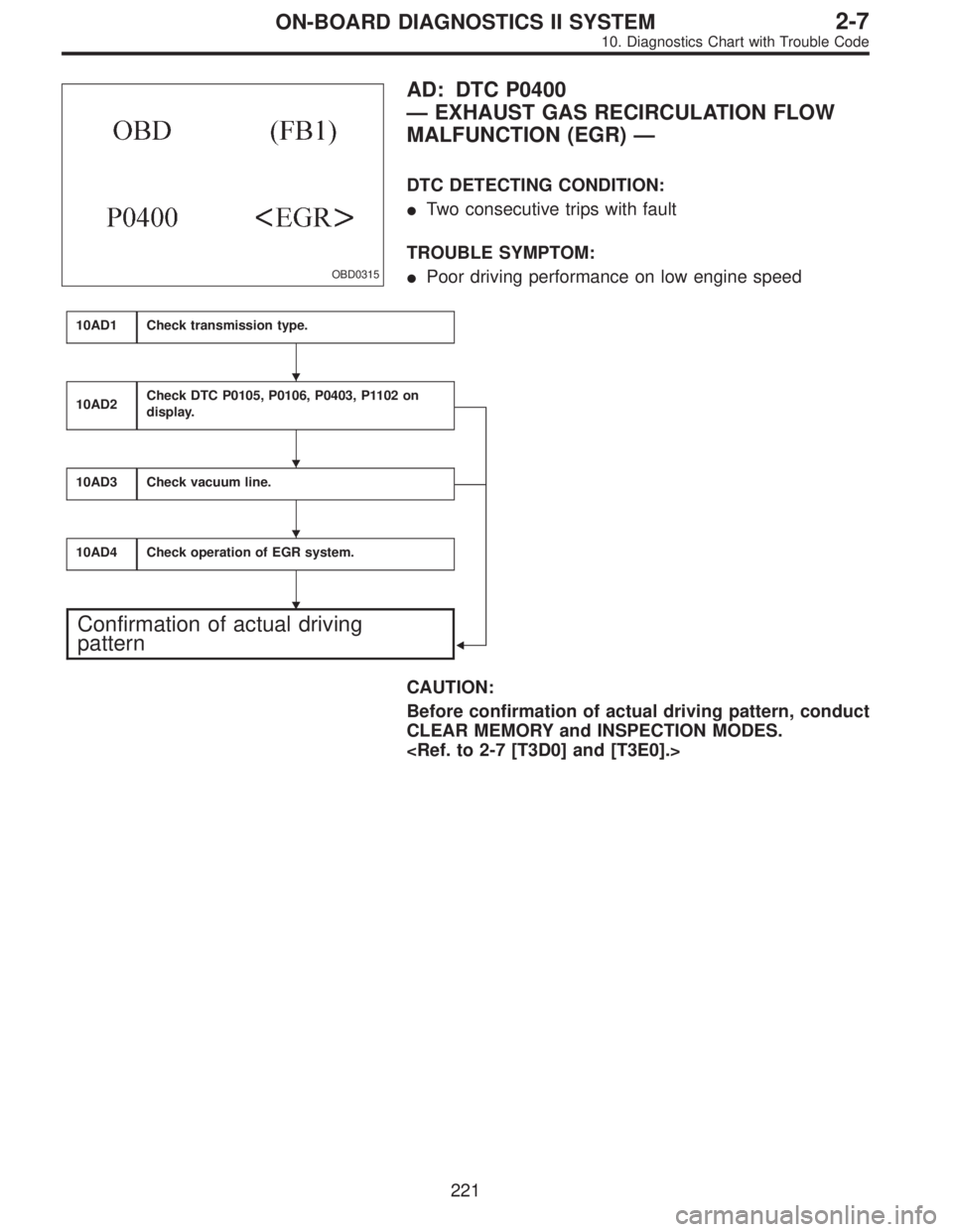
OBD0315
AD: DTC P0400
—EXHAUST GAS RECIRCULATION FLOW
MALFUNCTION (EGR)—
DTC DETECTING CONDITION:
�Two consecutive trips with fault
TROUBLE SYMPTOM:
�Poor driving performance on low engine speed
10AD1Check transmission type.
10AD2Check DTC P0105, P0106, P0403, P1102 on
display.
�
10AD3Check vacuum line.
10AD4Check operation of EGR system.
Confirmation of actual driving
pattern
CAUTION:
Before confirmation of actual driving pattern, conduct
CLEAR MEMORY and INSPECTION MODES.
�
�
�
�
221
2-7ON-BOARD DIAGNOSTICS II SYSTEM
10. Diagnostics Chart with Trouble Code
Page 1993 of 2890
 Start the engine.
: Does EGR valve operate at a throttle valve
opening of 5 to 10 degrees with visually
check?
: Possibly EGR valve malfunction may be due to
freezing or clogging by foreign matter.")
7) Start the engine.
: Does EGR valve operate at a throttle valve
opening of 5 to 10 degrees with visually
check?
: Possibly EGR valve malfunction may be due to
freezing or clogging by foreign matter. At this point
in time do not replace EGR valve, since it is not
faulty. And after the checking, go to
CONFIR-
MATION OF ACTUAL DRIVING PAT-
TERN.
NOTE:
If malfunction is detected again in the confirmation of actual
driving pattern, EGR valve is faulty. Go to next
.
: Go to next.
: Is there clogging in the gas outlets of intake
manifold or cylinder head, checking by
breathing into the outlets?
: Repair or replace intake manifold or cylinder
head. And go to
CONFIRMATION OF
ACTUAL DRIVING PATTERN.
: Clean EGR valve. And go toCONFIRMATION
OF ACTUAL DRIVING PATTERN.
CAUTION:
Do not use solvent when cleaning EGR valve
assembly, as it can damage diaphragm.
NOTE:
�Remove and blow away the exhaust deposits. Make
sure the valve operates smoothly and the valve seat area
is completely cleaned.
�Replace EGR valve as required.
225
2-7ON-BOARD DIAGNOSTICS II SYSTEM
10. Diagnostics Chart with Trouble Code
Page 1995 of 2890
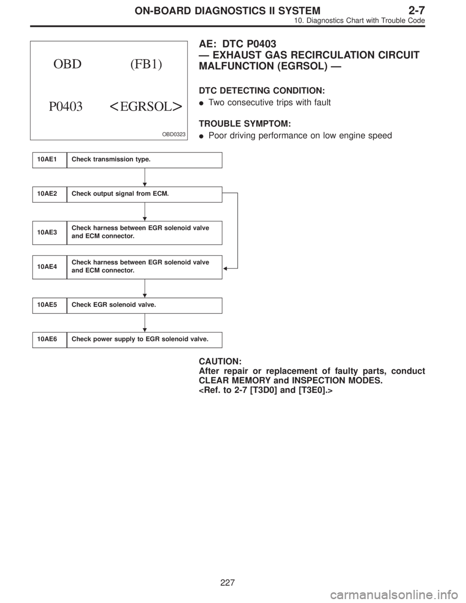
OBD0323
AE: DTC P0403
—EXHAUST GAS RECIRCULATION CIRCUIT
MALFUNCTION (EGRSOL)—
DTC DETECTING CONDITION:
�Two consecutive trips with fault
TROUBLE SYMPTOM:
�Poor driving performance on low engine speed
10AE1Check transmission type.
10AE2Check output signal from ECM.
�
10AE3Check harness between EGR solenoid valve
and ECM connector.
10AE4Check harness between EGR solenoid valve
and ECM connector.
10AE5Check EGR solenoid valve.
10AE6Check power supply to EGR solenoid valve.
CAUTION:
After repair or replacement of faulty parts, conduct
CLEAR MEMORY and INSPECTION MODES.
�
�
�
�
227
2-7ON-BOARD DIAGNOSTICS II SYSTEM
10. Diagnostics Chart with Trouble Code
Page 1999 of 2890
 Turn ignition switch to OFF.
6) Measure resistance between EGR solenoid valve ter-
minals.
: Terminals
No. 1—No. 2:
Is the resistance less than 1Ω?
: Replace EGR solenoid valve and ECM.")
OBD0327
5) Turn ignition switch to OFF.
6) Measure resistance between EGR solenoid valve ter-
minals.
: Terminals
No. 1—No. 2:
Is the resistance less than 1Ω?
: Replace EGR solenoid valve and ECM.
: Go to next.
: Is there poor contact in ECM connector?
: Repair poor contact in ECM connector.
: Replace ECM.
OBD0678A
10AE4CHECK HARNESS BETWEEN EGR
SOLENOID VALVE AND ECM CONNEC-
TOR.
1) Turn ignition switch to OFF.
2) Disconnect connectors from EGR solenoid valve and
ECM.
3) Measure resistance of harness between EGR solenoid
valve connector and engine ground.
: Connector & terminal
(E18) No. 2—Engine ground:
Is the resistance less than 10Ω?
: Repair short circuit in harness between ECM and
EGR solenoid valve connector.
: Go to next step 4).
B2M0567A
4) Measure resistance of harness between ECM and EGR
solenoid valve connector.
: Connector & terminal
(B84) No. 71—(E18) No. 2:
Is the resistance less than 1Ω?
: Go to step10AE5.
: Repair open circuit in harness between ECM and
EGR solenoid valve connector.
231
2-7ON-BOARD DIAGNOSTICS II SYSTEM
10. Diagnostics Chart with Trouble Code
Page 2000 of 2890
OBD0327
10AE5
CHECK EGR SOLENOID VALVE.
Measure resistance between EGR solenoid valve termi-
nals.
: Terminals
No. 1—No. 2:
Is the resistance between 10 and 100Ω?
: Go to step10AE6.
: Replace EGR solenoid valve.
OBD0328A
10AE6CHECK POWER SUPPLY TO EGR SOLE-
NOID VALVE.
1) Turn ignition switch to ON.
2) Measure voltage between EGR solenoid valve and
engine ground.
: Connector & terminal
(E18) No. 1 (+)—Engine ground (�):
Is the voltage more than 10 V?
: Go to next.
: Repair open circuit in harness between main relay
and EGR solenoid valve connector.
: Is there poor contact in EGR solenoid valve
connector?
: Repair poor contact in EGR solenoid valve con-
nector.
: Contact with SOA service.
NOTE:
Inspection by DTM is required, because probable cause is
deterioration of multiple parts.
232
2-7ON-BOARD DIAGNOSTICS II SYSTEM
10. Diagnostics Chart with Trouble Code
Page 2001 of 2890
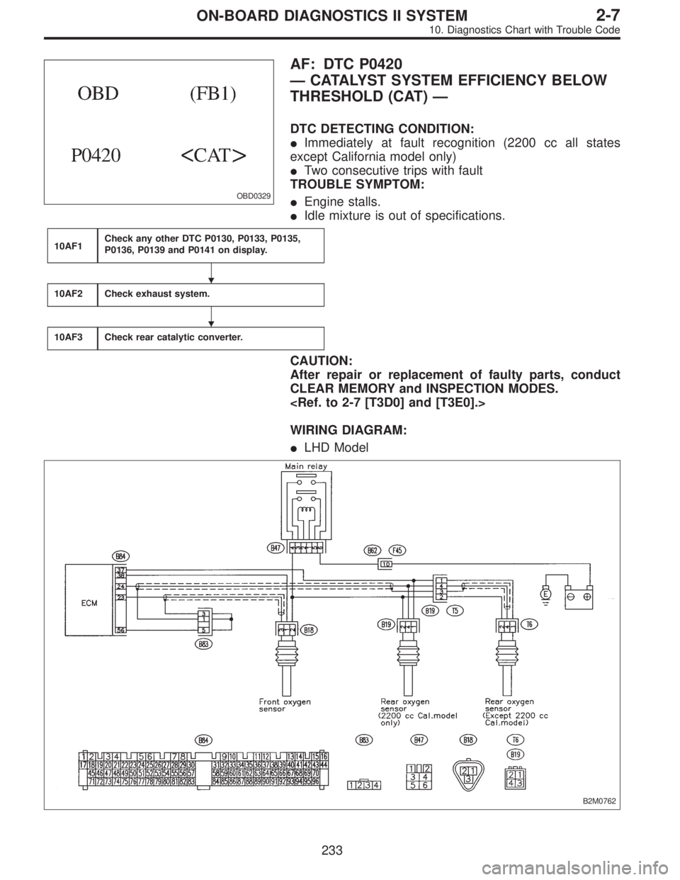
OBD0329
AF: DTC P0420
—CATALYST SYSTEM EFFICIENCY BELOW
THRESHOLD (CAT)—
DTC DETECTING CONDITION:
�Immediately at fault recognition (2200 cc all states
except California model only)
�Two consecutive trips with fault
TROUBLE SYMPTOM:
�Engine stalls.
�Idle mixture is out of specifications.
10AF1Check any other DTC P0130, P0133, P0135,
P0136, P0139 and P0141 on display.
10AF2Check exhaust system.
10AF3Check rear catalytic converter.
CAUTION:
After repair or replacement of faulty parts, conduct
CLEAR MEMORY and INSPECTION MODES.
WIRING DIAGRAM:
�LHD Model
B2M0762
�
�
233
2-7ON-BOARD DIAGNOSTICS II SYSTEM
10. Diagnostics Chart with Trouble Code
Page 2015 of 2890
 Turn ignition switch to OFF.
2) Disconnect connectors from purge control solenoid
valve and ECM.
3) Measure resis")
OBD0680A
10AI3CHECK HARNESS BETWEEN PURGE
CONTROL SOLENOID VALVE AND ECM
CONNECTOR.
1) Turn ignition switch to OFF.
2) Disconnect connectors from purge control solenoid
valve and ECM.
3) Measure resistance of harness between purge control
solenoid valve connector and engine ground.
: Connector & terminal
(E4) No. 2—Engine ground:
Is the resistance less than 10Ω?
: Repair short circuit in harness between ECM and
purge control solenoid valve connector.
: Go to next step 4).
B2M0571A
4) Measure resistance of harness between ECM and
purge control solenoid valve of harness connector.
: Connector & terminal
(B84) No. 72—(E4) No. 2:
Is the resistance less than 1Ω?
: Go to step10AI4.
: Repair open circuit in harness between ECM and
purge control solenoid valve connector.
OBD0338
10AI4CHECK PURGE CONTROL SOLENOID
VA LV E .
1) Remove purge control solenoid valve.
2) Measure resistance between purge control solenoid
valve terminals.
: Terminals
No. 1—No. 2:
Is the resistance between 10 and 100Ω?
: Go to step10AI5.
: Replace purge control solenoid valve.
247
2-7ON-BOARD DIAGNOSTICS II SYSTEM
10. Diagnostics Chart with Trouble Code
Page 2016 of 2890
OBD0339A
10AI5CHECK POWER SUPPLY TO PURGE
CONTROL SOLENOID VALVE.
1) Turn ignition switch to ON.
2) Measure voltage between purge control solenoid valve
and engine ground.
: Connector & terminal
(E4) No. 1 (+)—Engine ground (�):
Is the voltage more than 10 V?
: Go to next.
: Repair open circuit in harness between main relay
and purge control solenoid valve connector.
: Is there poor contact in purge control sole-
noid valve connector?
: Repair poor contact in purge control solenoid
valve connector.
: Contact with SOA service.
NOTE:
Inspection by DTM is required, because probable cause is
deterioration of multiple parts.
248
2-7ON-BOARD DIAGNOSTICS II SYSTEM
10. Diagnostics Chart with Trouble Code

 Turn ignition switch to ON.
2) Measure voltage between purge control solenoid valve
and engine ground.
: Connector & terminal
(E4)")