Page 1930 of 2890
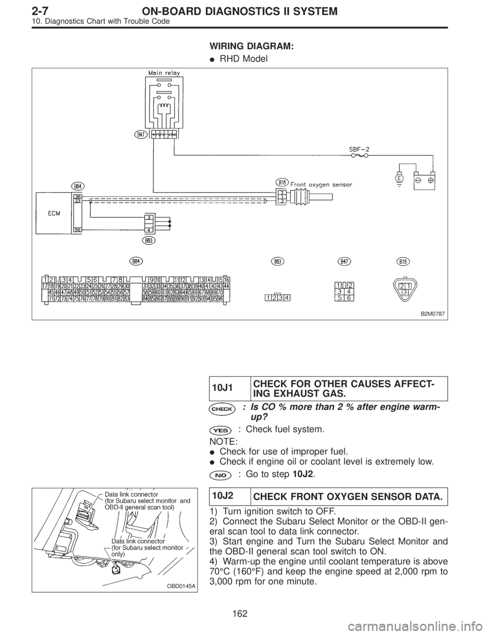
WIRING DIAGRAM:
�RHD Model
B2M0787
10J1CHECK FOR OTHER CAUSES AFFECT-
ING EXHAUST GAS.
: Is CO % more than 2 % after engine warm-
up?
: Check fuel system.
NOTE:
�Check for use of improper fuel.
�Check if engine oil or coolant level is extremely low.
: Go to step10J2.
OBD0145A
10J2
CHECK FRONT OXYGEN SENSOR DATA.
1) Turn ignition switch to OFF.
2) Connect the Subaru Select Monitor or the OBD-II gen-
eral scan tool to data link connector.
3) Start engine and Turn the Subaru Select Monitor and
the OBD-II general scan tool switch to ON.
4) Warm-up the engine until coolant temperature is above
70°C (160°F) and keep the engine speed at 2,000 rpm to
3,000 rpm for one minute.
162
2-7ON-BOARD DIAGNOSTICS II SYSTEM
10. Diagnostics Chart with Trouble Code
Page 1931 of 2890
 Read data on Subaru Select Monitor or the OBD-II gen-
eral scan tool.
�Subaru Select Monitor
Designate mode using function key.
Function mode: F12
�F12: Front oxygen sensor max. and min. ou")
B2M0487
5) Read data on Subaru Select Monitor or the OBD-II gen-
eral scan tool.
�Subaru Select Monitor
Designate mode using function key.
Function mode: F12
�F12: Front oxygen sensor max. and min. output signals
are indicated at the same time.
: Is the difference of voltage less than 0.1 V
between the value of max. output and min.
output with function mode F12?
: Go to step10J3.
: Replace front oxygen sensor.
�OBD-II general scan tool
For detailed operation procedures, refer to the OBD-II Gen-
eral Scan Tool Instruction Manual.
B2M0545A
10J3CHECK HARNESS BETWEEN FRONT
OXYGEN SENSOR AND ECM CONNEC-
TOR.
1) Turn ignition switch to OFF.
2) Disconnect connector from front oxygen sensor.
3) Turn ignition switch to ON.
4) Measure voltage between front oxygen sensor harness
connector and engine ground.
: Connector & terminal
(B18) No. 3 (+)—Engine ground (�):
Is the voltage more than 0.2 V?
: Go to next.
: Repair harness and connector.
NOTE:
In this case, repair the following:
�Open circuit in harness between ECM and front oxygen
sensor connector
�Poor contact in the ECM connector
: Is there poor contact in front oxygen sensor
connector?
: Repair poor contact in front oxygen sensor con-
nector.
: Replace front oxygen sensor.
163
2-7ON-BOARD DIAGNOSTICS II SYSTEM
10. Diagnostics Chart with Trouble Code
Page 1937 of 2890
10L1
CHECK DTC P0141 ON DISPLAY.
: Does the Subaru select monitor or OBD-II
general scan tool indicate DTC P0135 and
P0141 at the same time?
: Go to next step 1).
: Go to step10L2.
B2M0547A
1) Turn ignition switch to OFF.
2) Disconnect connector from ECM.
3) Measure resistance of harness between ECM connec-
tor and chassis ground.
: Connector & terminal
(B84) No. 42—Chassis ground:
Is the resistance less than 5Ω?
: Repair poor contact in ECM connector.
: Repair harness and connector.
NOTE:
In this case, repair the following:
�Open circuit in harness between ECM and coupling con-
nector (B22)
�Open circuit in harness between coupling connector
(B22) and engine grounding terminal
�Poor contact in front oxygen sensor connector
�Poor contact in coupling connector (B22)
169
2-7ON-BOARD DIAGNOSTICS II SYSTEM
10. Diagnostics Chart with Trouble Code
Page 1938 of 2890
 Turn ignition switch to OFF.
2) Connect Subaru Select Monitor or the OBD-II general
scan tool to data link")
OBD0145A
10L2CONNECT SUBARU SELECT MONITOR
OR THE OBD-II GENERAL SCAN TOOL,
AND READ DATA.
1) Turn ignition switch to OFF.
2) Connect Subaru Select Monitor or the OBD-II general
scan tool to data link connector.
3) Turn ignition switch to ON and Subaru Select Monitor or
OBD-II general scan tool switch to ON.
4) Start engine.
B2M0497
5) Read data on Subaru Select Monitor or OBD-II general
scan tool.
�Subaru Select Monitor
Designate mode using function key.
Function mode: F32
�F32: Front oxygen sensor heater current is indicated.
: Is the value more than 0.2 A in function
mode F32?
: Repair connector.
NOTE:
In this case, repair the following:
�Poor contact in front oxygen sensor connector
�Poor contact in ECM connector
: Go to step10L3.
�OBD-II scan tool
For detailed operation procedures, refer to the OBD-II Gen-
eral Scan Tool Instruction Manual.
B2M0548A
10L3CHECK OUTPUT SIGNAL FROM ECM.
(USING VOLTAGE METER.)
1) Start and idle the engine.
2) Measure voltage between ECM connector and chassis
ground.
: Connector & terminal
(B84) No. 38 (+)—Chassis ground (�):
Is the voltage less than 1.0 V?
: Go to step10L4.
: Go to next.
: Does the voltage change less than 1.0 V by
shaking harness and connector of ECM
while monitoring the value with voltage
meter?
: Repair poor contact in ECM connector.
: Go to next step 3).
170
2-7ON-BOARD DIAGNOSTICS II SYSTEM
10. Diagnostics Chart with Trouble Code
Page 1939 of 2890
 Disconnect connector from front oxygen sensor.
4) Measure voltage between ECM connector and chassis
ground.
: Connector & terminal
(B84) No. 38 (+)—Chassis ground (�):
Is the voltage les")
B2M0548A
3) Disconnect connector from front oxygen sensor.
4) Measure voltage between ECM connector and chassis
ground.
: Connector & terminal
(B84) No. 38 (+)—Chassis ground (�):
Is the voltage less than 1.0 V?
: Replace ECM.
: Repair short circuit in harness between ECM and
front oxygen sensor connector. After repair short
circuit of harness, replace ECM.
B2M0549A
10L4CHECK POWER SUPPLY TO FRONT
OXYGEN SENSOR.
1) Turn ignition switch to OFF.
2) Disconnect connector from front oxygen sensor.
3) Turn ignition switch to ON.
4) Measure voltage between front oxygen sensor connec-
tor and engine ground.
: Connector & terminal
(B18) No. 2 (+)—Engine ground (�):
Is the voltage more than 10 V?
: Go to step10L5.
: Repair power supply line.
NOTE:
In this case, repair the following:
�Open circuit in harness between main relay and front
oxygen sensor connector
�Poor contact in front oxygen sensor connector
�Poor contact in main relay connector
B2M0768
10L5
CHECK FRONT OXYGEN SENSOR.
1) Turn ignition switch to OFF.
2) Measure resistance between front oxygen sensor con-
nector terminals.
: Terminals
No. 1—No. 2:
Is the resistance less than 30Ω?
: Repair harness and connector.
NOTE:
In this case, repair the following:
�Open circuit in harness between front oxygen sensor
and ECM connector
�Poor contact in front oxygen sensor connector
�Poor contact in ECM connector
: Replace front oxygen sensor.
171
2-7ON-BOARD DIAGNOSTICS II SYSTEM
10. Diagnostics Chart with Trouble Code
Page 1943 of 2890

10M1
CHECK DTC P0130 ON DISPLAY.
: Does the Subaru select monitor or OBD-II
general scan tool indicate DTC P0130?
: Go to step10M2.
: Go to step10M3.
10M2
CHECK FAILURE CAUSE OF P0130.
Perform the step 1 of DTC P0130.
: Is the failure cause of P0130 in the fuel sys-
tem?
: Check fuel system.
NOTE:
In this case, it is not necessary to inspect DTC P0136.
: Go to step10M3.
OBD0145A
10M3
CHECK REAR OXYGEN SENSOR DATA.
1) Turn ignition switch to OFF.
2) Connect Subaru Select Monitor or OBD-II general scan
tool to data link connector.
3) Start the engine, and turn Subaru Select Monitor or
OBD-II general scan tool switch to ON.
4) Warm-up the engine until engine coolant temperature is
above 70°C (160°F), and keep the engine speed at 2,000
rpm to 3,000 rpm for two minutes.
B2M0488
5) Read data on Subaru Select Monitor or OBD-II general
scan tool.
�Subaru Select Monitor
Designate mode using function key.
Function mode: F13
�F13: Rear oxygen sensor output signal is indicated.
: Does the value fluctuate in function mode
F13?
: Go to step10M5.
: Go to next.
175
2-7ON-BOARD DIAGNOSTICS II SYSTEM
10. Diagnostics Chart with Trouble Code
Page 1944 of 2890

B2M0488
: Is the value fixed between 0.2 and 0.4 V in
function mode F13?
: Go to step10M4.
: Replace rear oxygen sensor.
�OBD-II general scan tool
For detailed operation procedures, refer to the OBD-II Gen-
eral Scan Tool Instruction Manual.
OBD0707C
10M4CHECK HARNESS BETWEEN REAR
OXYGEN SENSOR AND ECM CONNEC-
TOR.
1) Turn ignition switch to OFF.
2) Disconnect connector from rear oxygen sensor.
3) Turn ignition switch to ON.
4) Measure voltage between rear oxygen sensor harness
connector and engine ground or chassis ground.
: Connector & terminal
�2200 cc California model
(B19) No. 4 (+)—Engine ground (�):
�Except 2200 cc California model
(T6) No. 4 (+)—Chassis ground (�):
Is the voltage more than 0.2 V?
: Replace rear oxygen sensor.
: Repair harness and connector.
NOTE:
In this case, repair the following:
�Open circuit in harness between rear oxygen sensor and
ECM connector
�Poor contact in rear oxygen sensor connector
�Poor contact in ECM connector
�Poor contact in rear oxygen sensor connecting harness
connector (Except 2200 cc California model)
10M5
CHECK EXHAUST SYSTEM.
: Is there a fault in exhaust system?
NOTE:
Check the following items.
�Loose installation of portions
�Damage (crack, hole etc.) of parts
�Looseness and ill fitting of parts between front oxygen
sensor and rear oxygen sensor
: Repair or replace faulty parts.
: Replace rear oxygen sensor.
176
2-7ON-BOARD DIAGNOSTICS II SYSTEM
10. Diagnostics Chart with Trouble Code
Page 1951 of 2890
B2M0554A
10O3CHECK OUTPUT SIGNAL FROM ECM.
(USING VOLTAGE METER.)
1) Start and idle the engine.
2) Measure voltage between ECM connector and chassis
ground.
: Connector & terminal
(B84) No. 37 (+)—Chassis ground (�):
Is the voltage less than 1.0 V?
: Go to step10O4.
: Go to next.
: Does the voltage change less than 1.0 V by
shaking harness and connector of ECM
while monitoring the value with voltage
meter?
: Repair poor contact in ECM connector.
: Go to next step 3).
B2M0554A
3) Disconnect connector from rear oxygen sensor.
4) Measure voltage between ECM connector and chassis
ground.
: Connector & terminal
(B84) No. 37 (+)—Chassis ground (�):
Is the voltage less than 1.0 V?
: Replace ECM.
: Repair short circuit in harness between ECM and
rear oxygen sensor connector. After repair short
circuit in harness, replace ECM.
183
2-7ON-BOARD DIAGNOSTICS II SYSTEM
10. Diagnostics Chart with Trouble Code
.
: Go to step10L2.
B2M0547A
1) Turn ig")

1) Start and idle the engine.
2) Measure voltage between ECM connector and chassis
ground.
: Connector & terminal
(B84) No. 37 (+)—C")