Page 1886 of 2890

Throttle position sensor
Crankshaft position sensor & Camshaft po")
9. General Diagnostics Table
1. FOR ENGINE
12345678910111213
Problem parts
Mass air flow sensor
Engine coolant temperature sensor (*1)
Throttle position sensor
Crankshaft position sensor & Camshaft position sensor (*2)
Idle air control solenoid valve
Knock sensor
Purge control solenoid valve
EGR valve
Fuel injection parts (*3)
Ignition parts (*4)
Fuel pump and relay
A/C switch and A/C cut relay
Engine torque control signal circuitSymptom
1 Engine stalls during idling.�� � � ���
2 Rough idling�� � � � �
3 Engine does not return to idle.���
4 Poor acceleration�� � � ���
5Engine stalls or engine sags or hesi-
tates at acceleration.�� � � ��� �
6 Surge�� � �� �
7 Spark knock����
8 After burning in exhaust system�� � �
*1: The mark,�, indicates the symptom occurring only in cold temperatures.
*2: For items with the mark,�, ensure the secure installation of crankshaft position sensor and camshaft position sensor. Replacement is
not necessary.
*3: Check fuel injector, fuel pressure regulator and fuel filter.
*4: Check ignitor, ignition coil and spark plug.
NOTE:
Malfunction of parts other than the above is also possible. Refer to 1. Engine Trouble in General [K100] in Repair Section 2-3 or 2-3b of
the Service Manual.
11 8
2-7ON-BOARD DIAGNOSTICS II SYSTEM
9. General Diagnostics Table
Page 1892 of 2890
Item Page
P0500 VSP Vehicle speed sensor malfunction 266
P0505 ISC Idle control system malfunction 269
P0506 ISC
—L Idle control system RPM lower than expe")
DTC
No.Abbreviation
(Subaru select monitor)Item Page
P0500 VSP Vehicle speed sensor malfunction 266
P0505 ISC Idle control system malfunction 269
P0506 ISC
—L Idle control system RPM lower than expected 276
P0507 ISC
—H Idle control system RPM higher than expected 277
P0600—Serial communication link malfunction 278
P0601 RAM Internal control module memory check sum error 281
P0703 ATBRK Brake switch input malfunction 283
P0705 ATRNG Transmission range sensor circuit malfunction 286
P0710 ATF Transmission fluid temperature sensor circuit malfunction 293
P0720 ATVSP Output speed sensor (vehicle speed sensor 1) circuit malfunction 294
P0725 ATNE Engine speed input circuit malfunction 295
P0731 ATGR1 Gear 1 incorrect ratio
296 P0732 ATGR2 Gear 2 incorrect ratio
P0733 ATGR3 Gear 3 incorrect ratio
P0734 ATGR4 Gear 4 incorrect ratio
P0740 ATLU
—F Torque converter clutch system malfunction 300
P0743 ATLU Torque converter clutch system electrical 304
P0748 ATPL Pressure control solenoid electrical 305
P0753 ATSFT1 Shift solenoid A electrical 306
P0758 ATSFT2 Shift solenoid B electrical 307
P0760 ATOVR
—F Shift solenoid C malfunction 308
P0763 ATOVR Shift solenoid C electrical 312
P1100 ST
—SW Starter switch circuit malfunction 313
P1101 N/P
—SW Neutral position switch circuit malfunction [MT vehicles] 315
P1101 N/P
—SW Neutral position switch circuit malfunction [AT vehicles] 318
P1102 BR Pressure sources switching solenoid valve circuit malfunction 322
P1103 TRQ Engine torque control signal circuit malfunction 328
P1400 PCVSOL Fuel tank pressure control solenoid valve circuit malfunction 331
P1401 PCV
—F Fuel tank pressure control system function problem 337
P1402 FLVL Fuel level sensor circuit malfunction 339
P1500 FAN
—1 Radiator fan relay 1 circuit malfunction 351
P1502 FAN
—F Radiator fan function problem 358
P1700 ATTH Throttle position sensor circuit malfunction for automatic transmission 361
P1701 ATCRS Cruise control set signal circuit malfunction for automatic transmission 362
P1702 ATDIAG Automatic transmission diagnosis input signal circuit malfunction 365
P0461*1 EXERR22 Fuel level sensor circuit range/performance problem 368
*1: Only OBD-II general scan tool displays DTC.
124
2-7ON-BOARD DIAGNOSTICS II SYSTEM
10. Diagnostics Chart with Trouble Code
Page 1893 of 2890
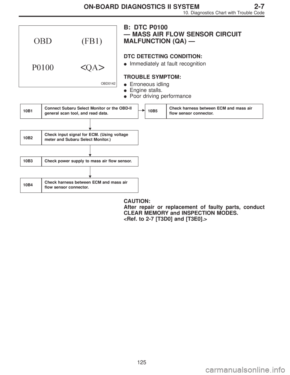
OBD0142
B: DTC P0100
—MASS AIR FLOW SENSOR CIRCUIT
MALFUNCTION (QA)—
DTC DETECTING CONDITION:
�Immediately at fault recognition
TROUBLE SYMPTOM:
�Erroneous idling
�Engine stalls.
�Poor driving performance
10B1Connect Subaru Select Monitor or the OBD-II
general scan tool, and read data.�10B5Check harness between ECM and mass air
flow sensor connector.
10B2Check input signal for ECM. (Using voltage
meter and Subaru Select Monitor.)
10B3Check power supply to mass air flow sensor.
10B4Check harness between ECM and mass air
flow sensor connector.
CAUTION:
After repair or replacement of faulty parts, conduct
CLEAR MEMORY and INSPECTION MODES.
�
�
�
125
2-7ON-BOARD DIAGNOSTICS II SYSTEM
10. Diagnostics Chart with Trouble Code
Page 1897 of 2890

Measure voltage between ECM connector and chassis
ground while engine is idling.
: Connector & terminal
(B84)")
B2M0532A
10B2CHECK INPUT SIGNAL FOR ECM.
(USING VOLTAGE METER AND SUBARU
SELECT MONITOR.)
Measure voltage between ECM connector and chassis
ground while engine is idling.
: Connector & terminal
(B84) No. 5 (+)—Chassis ground (�):
Is the voltage less than 0.3 V?
: Go to step10B3.
: Go to next.
B2M0481
: Does the voltage change more than 0.3 V by
shaking harness and connector of ECM
while monitoring the value with Subaru
select monitor?
: Repair poor contact in ECM connector.
: Replace ECM.
B2M0645A
10B3CHECK POWER SUPPLY TO MASS AIR
FLOW SENSOR.
1) Turn ignition switch to OFF.
2) Disconnect connector from mass air flow sensor.
3) Turn ignition switch to ON.
4) Measure voltage between mass air flow sensor connec-
tor and engine ground.
: Connector & terminal
(B3) No. 1 (+)—Engine ground (�):
Is the voltage more than 10 V?
: Go to step10B4.
: Repair open circuit in harness between main relay
and mass air flow sensor connector.
129
2-7ON-BOARD DIAGNOSTICS II SYSTEM
10. Diagnostics Chart with Trouble Code
Page 1900 of 2890
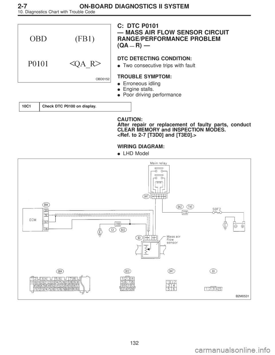
OBD0152
C: DTC P0101
—MASS AIR FLOW SENSOR CIRCUIT
RANGE/PERFORMANCE PROBLEM
(QA
—R)—
DTC DETECTING CONDITION:
�Two consecutive trips with fault
TROUBLE SYMPTOM:
�Erroneous idling
�Engine stalls.
�Poor driving performance
10C1Check DTC P0100 on display.
CAUTION:
After repair or replacement of faulty parts, conduct
CLEAR MEMORY and INSPECTION MODES.
WIRING DIAGRAM:
�LHD Model
B2M0531
132
2-7ON-BOARD DIAGNOSTICS II SYSTEM
10. Diagnostics Chart with Trouble Code
Page 1907 of 2890
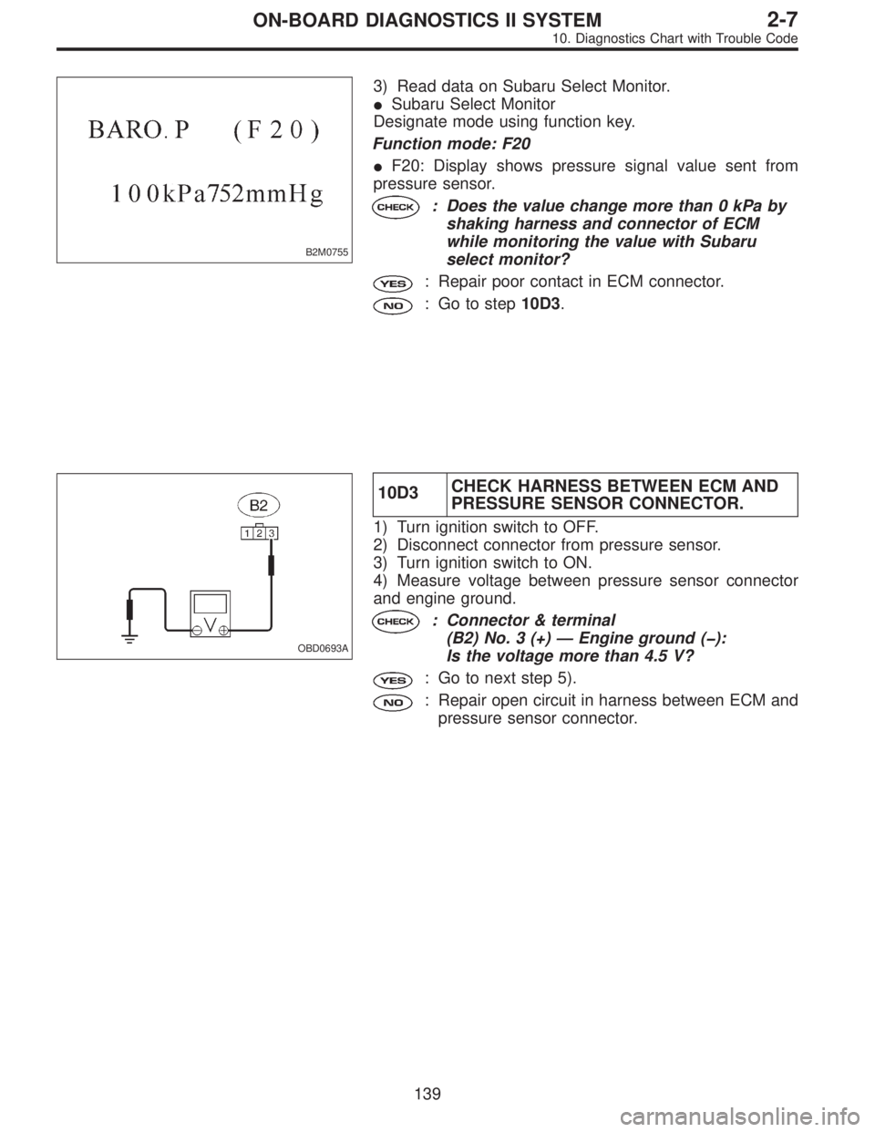
B2M0755
3) Read data on Subaru Select Monitor.
�Subaru Select Monitor
Designate mode using function key.
Function mode: F20
�F20: Display shows pressure signal value sent from
pressure sensor.
: Does the value change more than 0 kPa by
shaking harness and connector of ECM
while monitoring the value with Subaru
select monitor?
: Repair poor contact in ECM connector.
: Go to step10D3.
OBD0693A
10D3CHECK HARNESS BETWEEN ECM AND
PRESSURE SENSOR CONNECTOR.
1) Turn ignition switch to OFF.
2) Disconnect connector from pressure sensor.
3) Turn ignition switch to ON.
4) Measure voltage between pressure sensor connector
and engine ground.
: Connector & terminal
(B2) No. 3 (+)—Engine ground (�):
Is the voltage more than 4.5 V?
: Go to next step 5).
: Repair open circuit in harness between ECM and
pressure sensor connector.
139
2-7ON-BOARD DIAGNOSTICS II SYSTEM
10. Diagnostics Chart with Trouble Code
Page 1913 of 2890
 Turn ignition switch to OFF.
2) Connect Subaru Select Monitor or the OBD-II general
scan tool to data link connector.
3) Turn ignition switch ON and Subaru Sel")
OBD0145A
10E2
CHECK DATA FOR CONTROL.
1) Turn ignition switch to OFF.
2) Connect Subaru Select Monitor or the OBD-II general
scan tool to data link connector.
3) Turn ignition switch ON and Subaru Select Monitor or
the OBD-II general scan tool switch ON.
4) Start engine.
B2M0756
5) Read data on Subaru Select Monitor or the OBD-II gen-
eral scan tool.
�Subaru Select Monitor
Designate mode using function key.
Function mode: F21 and F20
�F21: Display shows pressure signal value sent from the
pressure sensor.
�F20: Display shows pressure signal value sent from the
pressure sensor.
: Is the value more than 85 kPa in function
mode F21?
: Go to step10E3.
: Go to next.
B2M0755
: Is the value less than 32 kPa in function
mode F20?
: Go to step10E4.
: Go to next.
B2M0755
: Is the value more than 133 kPa in function
mode F20?
: Replace pressure sensor.
: Repair poor contact in pressure sensor connector,
pressure sources switching solenoid valve
connector, and ECM connector.
�OBD-II general scan tool
For detailed operation procedures, refer to the OBD-II Gen-
eral Scan Tool Instruction Manual.
145
2-7ON-BOARD DIAGNOSTICS II SYSTEM
10. Diagnostics Chart with Trouble Code
Page 1915 of 2890
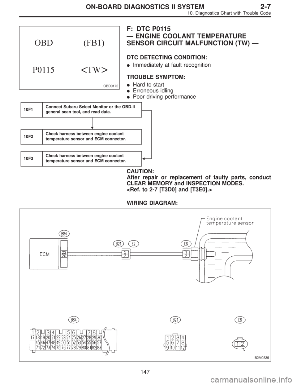
OBD0172
F: DTC P0115
—ENGINE COOLANT TEMPERATURE
SENSOR CIRCUIT MALFUNCTION (TW)—
DTC DETECTING CONDITION:
�Immediately at fault recognition
TROUBLE SYMPTOM:
�Hard to start
�Erroneous idling
�Poor driving performance
10F1Connect Subaru Select Monitor or the OBD-II
general scan tool, and read data.
�
10F2Check harness between engine coolant
temperature sensor and ECM connector.
10F3Check harness between engine coolant
temperature sensor and ECM connector.
CAUTION:
After repair or replacement of faulty parts, conduct
CLEAR MEMORY and INSPECTION MODES.
WIRING DIAGRAM:
B2M0539
�
147
2-7ON-BOARD DIAGNOSTICS II SYSTEM
10. Diagnostics Chart with Trouble Code