Page 1975 of 2890

: Has the vehicle been run empty of fuel?
: Finish diagnostics operation, if the engine has no
abnormality.
: Go to next.
: Was the cause of misfire diagnosed when
the engine is running?
NOTE:
Ex. Remove spark plug cord, etc.
: Finish diagnostics operation, if the engine has no
abnormality.
: Repair connector.
NOTE:
In this case, repair the following:
�Poor contact in ignitor connector
�Poor contact in ignition coil connector
�Poor contact in fuel injector connector on faulty cylinders
�Poor contact in ECM connector
�Poor contact in coupling connector (B22)
10Z3
CHECK AIR INTAKE SYSTEM.
: Is there a fault in air intake system?
NOTE:
Check the following items:
�Are there air leaks or air suction caused by loose or dis-
located nuts and bolts?
�Are there cracks or any disconnection of hoses?
: Repair air intake system.
: Go to step10Z4.
OBD0145A
10Z4
CHECK MISFIRE SYMPTOM.
1) Turn ignition switch to OFF.
2) Connect the Subaru Select Monitor or the OBD-II gen-
eral scan tool to data link connector.
3) Turn ignition switch to ON, and turn Subaru Select
Monitor or OBD-II general scan tool switch to ON.
207
2-7ON-BOARD DIAGNOSTICS II SYSTEM
10. Diagnostics Chart with Trouble Code
Page 1977 of 2890
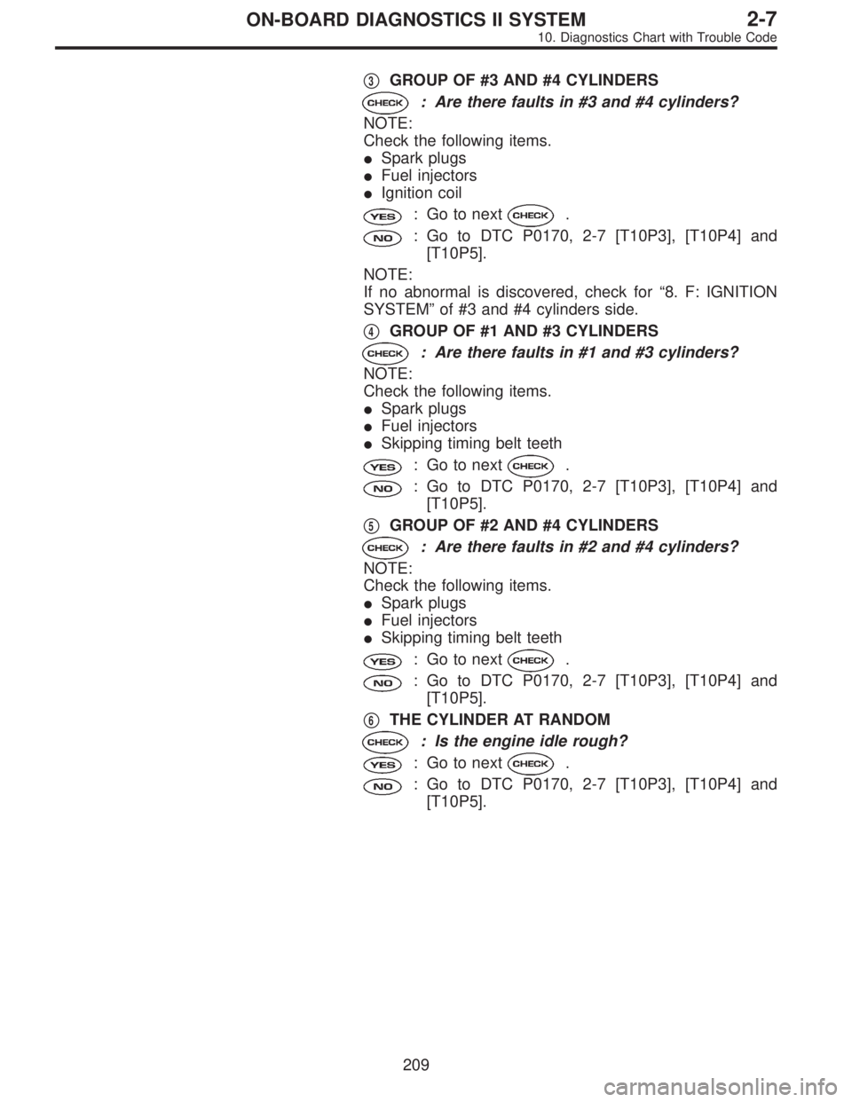
�3GROUP OF #3 AND #4 CYLINDERS
: Are there faults in #3 and #4 cylinders?
NOTE:
Check the following items.
�Spark plugs
�Fuel injectors
�Ignition coil
: Go to next.
: Go to DTC P0170, 2-7 [T10P3], [T10P4] and
[T10P5].
NOTE:
If no abnormal is discovered, check for“8. F: IGNITION
SYSTEM”of #3 and #4 cylinders side.
�
4GROUP OF #1 AND #3 CYLINDERS
: Are there faults in #1 and #3 cylinders?
NOTE:
Check the following items.
�Spark plugs
�Fuel injectors
�Skipping timing belt teeth
: Go to next.
: Go to DTC P0170, 2-7 [T10P3], [T10P4] and
[T10P5].
�
5GROUP OF #2 AND #4 CYLINDERS
: Are there faults in #2 and #4 cylinders?
NOTE:
Check the following items.
�Spark plugs
�Fuel injectors
�Skipping timing belt teeth
: Go to next.
: Go to DTC P0170, 2-7 [T10P3], [T10P4] and
[T10P5].
�
6THE CYLINDER AT RANDOM
: Is the engine idle rough?
: Go to next.
: Go to DTC P0170, 2-7 [T10P3], [T10P4] and
[T10P5].
209
2-7ON-BOARD DIAGNOSTICS II SYSTEM
10. Diagnostics Chart with Trouble Code
Page 1981 of 2890
 Turn ignition switch to OFF.
2) Disconnect connector from ECM.
3) Measure resistance between ECM harness connector
and chassis gr")
B2M0560A
10AA1CHECK HARNESS BETWEEN KNOCK
SENSOR AND ECM CONNECTOR.
1) Turn ignition switch to OFF.
2) Disconnect connector from ECM.
3) Measure resistance between ECM harness connector
and chassis ground.
: Connector & terminal
(B84) No. 3—Chassis ground:
Is the resistance more than 700 kΩ?
: Go to step10AA2.
: Go to next.
B2M0560A
: Connector & terminal
(B84) No. 3—Chassis ground:
Is the resistance less than 400 kΩ?
: Go to step10AA3.
: Go to step10AA4.
B2M0244A
10AA2
CHECK KNOCK SENSOR.
1) Disconnect connector from knock sensor.
2) Measure resistance between knock sensor connector
terminal and engine ground.
: Terminal
No. 1—Engine ground:
Is the resistance more than 700 kΩ?
: Go to next.
: Repair harness and connector.
NOTE:
In this case, repair the following:
�Open circuit in harness between knock sensor and ECM
connector
�Poor contact in knock sensor connector
�Poor contact in coupling connector (B21)
: Is the knock sensor installation bolt tight-
ened securely?
: Replace knock sensor.
: Tighten knock sensor installation bolt securely.
213
2-7ON-BOARD DIAGNOSTICS II SYSTEM
10. Diagnostics Chart with Trouble Code
Page 1982 of 2890
 Disconnect connector from knock sensor.
2) Measure resistance between knock sensor connector
terminal and engine ground.
: Terminal
No. 1—Engine ground:
Is the")
B2M0244A
10AA3
CHECK KNOCK SENSOR.
1) Disconnect connector from knock sensor.
2) Measure resistance between knock sensor connector
terminal and engine ground.
: Terminal
No. 1—Engine ground:
Is the resistance less than 400 kΩ?
: Replace knock sensor.
: Repair short circuit in harness between knock
sensor connector and ECM connector.
NOTE:
The harness between both connectors is shielded. Repair
short circuit of harness together with shield.
B2M0561A
10AA4
CHECK INPUT SIGNAL FOR ECM.
1) Connect connectors to ECM and knock sensor.
2) Turn ignition switch to ON.
3) Measure voltage between ECM and chassis ground.
: Connector & terminal
(B84) No. 3 (+)—Chassis ground (�):
Is the voltage more than 2 V?
: Even if MIL lights up, the circuit has returned to a
normal condition at this time. (However, the pos-
sibility of poor contact still remains.)
NOTE:
In this case, repair the following:
�Poor contact in knock sensor connector
�Poor contact in ECM connector
�Poor contact in coupling connector (B21)
: Repair poor contact in ECM connector.
214
2-7ON-BOARD DIAGNOSTICS II SYSTEM
10. Diagnostics Chart with Trouble Code
Page 1983 of 2890
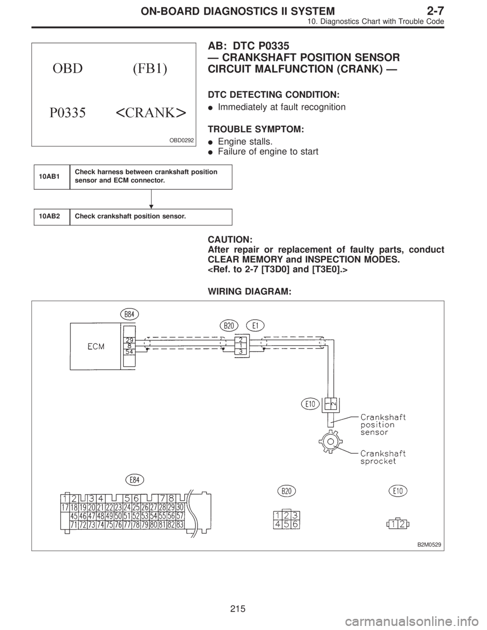
OBD0292
AB: DTC P0335
—CRANKSHAFT POSITION SENSOR
CIRCUIT MALFUNCTION (CRANK)—
DTC DETECTING CONDITION:
�Immediately at fault recognition
TROUBLE SYMPTOM:
�Engine stalls.
�Failure of engine to start
10AB1Check harness between crankshaft position
sensor and ECM connector.
10AB2Check crankshaft position sensor.
CAUTION:
After repair or replacement of faulty parts, conduct
CLEAR MEMORY and INSPECTION MODES.
WIRING DIAGRAM:
B2M0529
�
215
2-7ON-BOARD DIAGNOSTICS II SYSTEM
10. Diagnostics Chart with Trouble Code
Page 1984 of 2890
 Turn ignition switch to OFF.
2) Disconnect connector from crankshaft position sensor.
3) Measure resistance of ha")
OBD0718A
10AB1CHECK HARNESS BETWEEN CRANK-
SHAFT POSITION SENSOR AND ECM
CONNECTOR.
1) Turn ignition switch to OFF.
2) Disconnect connector from crankshaft position sensor.
3) Measure resistance of harness between crankshaft
position sensor connector and engine ground.
: Connector & terminal
(E10) No. 1—Engine ground:
Is the resistance more than 100 kΩ?
: Repair harness and connector.
NOTE:
In this case, repair the following:
�Open circuit in harness between crankshaft position
sensor and ECM connector
�Poor contact in ECM connector
�Poor contact in coupling connector (B20)
: Go to next.
OBD0718A
: Connector & terminal
(E10) No. 1—Engine ground:
Is the resistance less than 10Ω?
: Repair short circuit in harness between crankshaft
position sensor and ECM connector.
NOTE:
The harness between both connectors are shielded.
Repair short circuit in harness together with shield.
: Go to next.
OBD0719A
: Connector & terminal
(E10) No. 2—Engine ground:
Is the resistance less than 5Ω?
: Go to step10AB2.
: Repair harness and connector.
NOTE:
In this case, repair the following:
�Open circuit in harness between crankshaft position
sensor and ECM connector
�Poor contact in ECM connector
�Poor contact in coupling connector (B20)
216
2-7ON-BOARD DIAGNOSTICS II SYSTEM
10. Diagnostics Chart with Trouble Code
Page 1986 of 2890
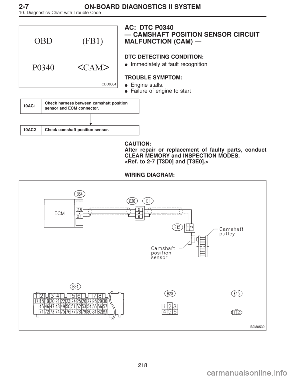
OBD0304
AC: DTC P0340
—CAMSHAFT POSITION SENSOR CIRCUIT
MALFUNCTION (CAM)—
DTC DETECTING CONDITION:
�Immediately at fault recognition
TROUBLE SYMPTOM:
�Engine stalls.
�Failure of engine to start
10AC1Check harness between camshaft position
sensor and ECM connector.
10AC2Check camshaft position sensor.
CAUTION:
After repair or replacement of faulty parts, conduct
CLEAR MEMORY and INSPECTION MODES.
WIRING DIAGRAM:
B2M0530
�
218
2-7ON-BOARD DIAGNOSTICS II SYSTEM
10. Diagnostics Chart with Trouble Code
Page 1987 of 2890
 Turn ignition switch to OFF.
2) Disconnect connector from camshaft position sensor.
3) Measure resistance of harnes")
OBD0720A
10AC1CHECK HARNESS BETWEEN CAM-
SHAFT POSITION SENSOR AND ECM
CONNECTOR.
1) Turn ignition switch to OFF.
2) Disconnect connector from camshaft position sensor.
3) Measure resistance of harness between camshaft posi-
tion sensor connector and engine ground.
: Connector & terminal
(E15) No. 1—Engine ground:
Is the resistance more than 100 kΩ?
: Repair harness and connector.
NOTE:
In this case, repair the following:
�Open circuit in harness between camshaft position sen-
sor and ECM connector
�Poor contact in ECM connector
�Poor contact in coupling connector (B20)
: Go to next.
OBD0720A
: Connector & terminal
(E15) No. 1—Engine ground:
Is the resistance less than 10Ω?
: Repair short circuit in harness between camshaft
position sensor connector and ECM connector.
NOTE:
The harness between both connectors are shielded.
Repair short circuit in harness together with shield.
: Go to next.
OBD0721A
: Connector & terminal
(E15) No. 2—Engine ground:
Is the resistance less than 5Ω?
: Go to step10AC2.
: Repair harness and connector.
NOTE:
In this case, repair the following:
�Open circuit in harness between camshaft position sen-
sor and ECM connector
�Poor contact in ECM connector
�Poor contact in coupling connector (B20)
219
2-7ON-BOARD DIAGNOSTICS II SYSTEM
10. Diagnostics Chart with Trouble Code