Page 1855 of 2890
B2M0515A
7D1CHECK HARNESS BETWEEN ECM CON-
NECTOR AND ENGINE GROUNDING
TERMINAL.
1) Turn ignition switch to OFF.
2) Disconnect connector from ECM.
3) Measure resistance of harness between ECM connec-
tor and chassis ground.
: Connector & terminal
(B84) No.84—Chassis ground:
Is resistance less than 5Ω?
: Repair short circuit in harness between ECM and
test mode connector.
: Replace ECM.
87
2-7ON-BOARD DIAGNOSTICS II SYSTEM
7. Diagnostics for CHECK ENGINE Malfunction Indicator Lamp (MIL)
Page 1857 of 2890
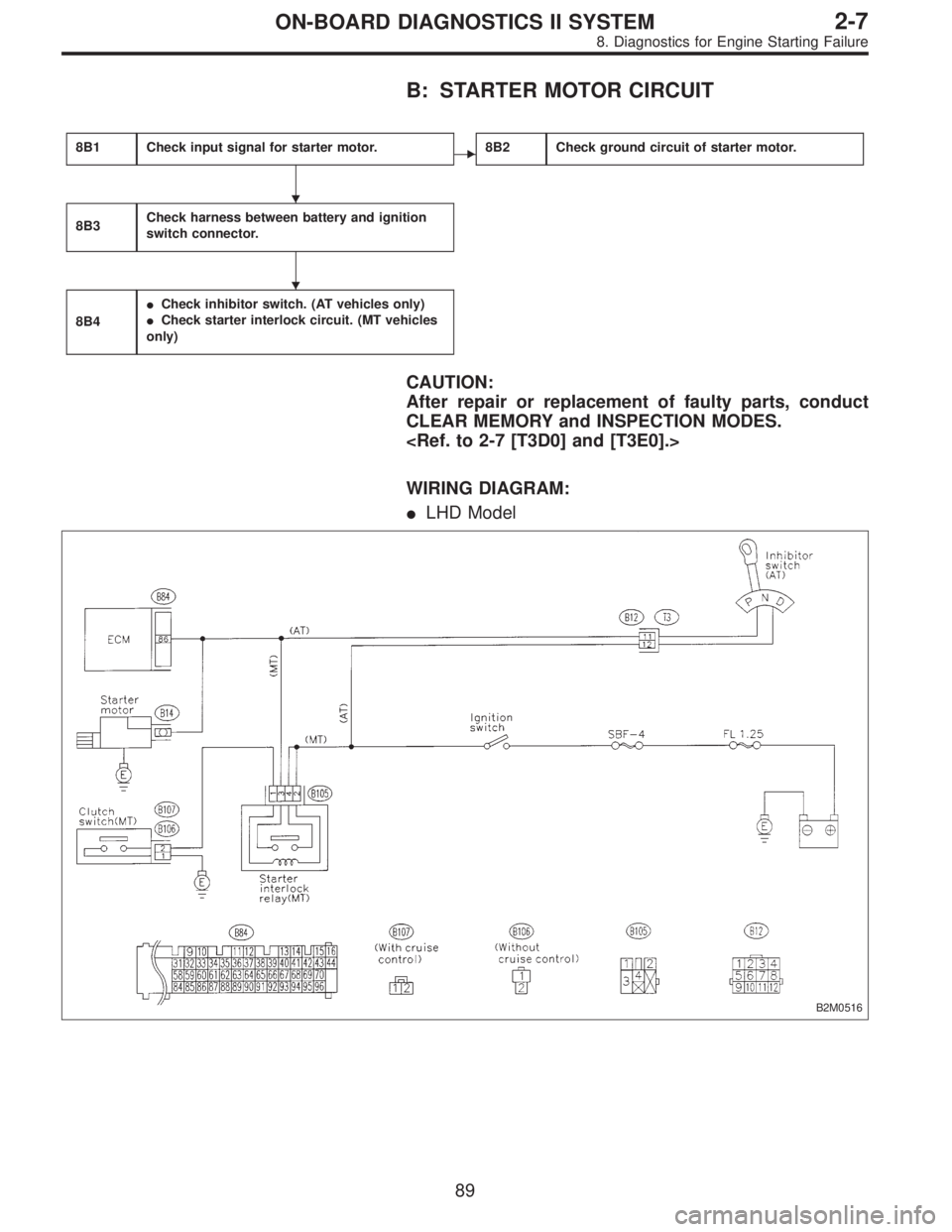
B: STARTER MOTOR CIRCUIT
8B1Check input signal for starter motor.�8B2Check ground circuit of starter motor.
8B3Check harness between battery and ignition
switch connector.
8B4
�Check inhibitor switch. (AT vehicles only)
�Check starter interlock circuit. (MT vehicles
only)
CAUTION:
After repair or replacement of faulty parts, conduct
CLEAR MEMORY and INSPECTION MODES.
WIRING DIAGRAM:
�LHD Model
B2M0516
�
�
89
2-7ON-BOARD DIAGNOSTICS II SYSTEM
8. Diagnostics for Engine Starting Failure
Page 1859 of 2890
 Turn ignition switch to OFF.
2) Disconnect connector from starter motor.
3) Turn ignition switch to ST.
OBD0100A
4) Measure power supply voltage bet")
OBD0724
8B1CHECK INPUT SIGNAL FOR STARTER
MOTOR.
1) Turn ignition switch to OFF.
2) Disconnect connector from starter motor.
3) Turn ignition switch to ST.
OBD0100A
4) Measure power supply voltage between starter motor
connector terminal and engine ground.
: Connector & terminal
(B14) No. 1 (+)—Engine ground (�):
Is the voltage more than 10 V?
NOTE:
�On AT vehicles, place the selector lever in the“P”or“N”
position.
�On MT vehicles, depress the clutch pedal.
: Go to step8B2.
: Go to step8B3.
OBD0725
8B2CHECK GROUND CIRCUIT OF STARTER
MOTOR.
1) Turn ignition switch to OFF.
2) Disconnect terminal from starter motor.
3) Measure resistance of ground cable between ground
cable terminal and engine ground.
: Is resistance less than 5Ω?
: Check starter motor.
: Repair open circuit of ground cable.
8B3CHECK HARNESS BETWEEN BATTERY
AND IGNITION SWITCH CONNECTOR.
1) Turn ignition switch to OFF.
2) Remove SBF No. 4 from main fuse box.
3) Measure resistance of fuse.
: Is resistance less than 1Ω?
: Replace SBF No. 4.
: Go to next step 4).
91
2-7ON-BOARD DIAGNOSTICS II SYSTEM
8. Diagnostics for Engine Starting Failure
Page 1860 of 2890
 Install SBF No. 4 to main fuse box.
5) Turn ignition switch to ON.
OBD0103A
6) Measure power supply voltage between ignition switch
connector and chassis ground.
: Connector & terminal
(B72) No. 1")
4) Install SBF No. 4 to main fuse box.
5) Turn ignition switch to ON.
OBD0103A
6) Measure power supply voltage between ignition switch
connector and chassis ground.
: Connector & terminal
(B72) No. 1 (+)—Chassis ground (�):
Is the voltage more than 10 V?
: Go to step8B4.
: Repair harness between ignition switch and SBF
No. 4 connector.
OBD0726A
8B4�CHECK INHIBITOR SWITCH. (AT
VEHICLES ONLY)
1) Turn ignition switch to OFF.
2) Disconnect connector from transmission.
3) Measure resistance between transmission harness
connector receptacle’s terminals.
: Connector & terminal
(T3) No. 11—No. 12:
Is the resistance less than 10Ω?
: Repair harness between starter motor and ignition
switch connector.
: Repair or replace inhibitor switch.
B2M0517A
8B4�CHECK STARTER INTERLOCK CIR-
CUIT. (MT VEHICLES ONLY)
1) Turn ignition switch to“ST”.
2) Measure voltage between clutch switch connector and
chassis ground.
92
2-7ON-BOARD DIAGNOSTICS II SYSTEM
8. Diagnostics for Engine Starting Failure
Page 1862 of 2890
C: CONTROL MODULE POWER SUPPLY AND
GROUND LINE
8C1Check main relay.
8C2Check power supply circuit of ECM.
8C3Check ground circuit of ECM.
CAUTION:
After repair or replacement of faulty parts, conduct
CLEAR MEMORY and INSPECTION MODES.
WIRING DIAGRAM:
�LHD Model
B2M0519
�
�
94
2-7ON-BOARD DIAGNOSTICS II SYSTEM
8. Diagnostics for Engine Starting Failure
Page 1864 of 2890
 Turn the ignition switch to OFF.
2) Remove main relay.
3) Connect battery to main relay terminals No. 1 and No.
2.
4) Measure resistance between main relay terminals.")
G2M0444
8C1
CHECK MAIN RELAY.
1) Turn the ignition switch to OFF.
2) Remove main relay.
3) Connect battery to main relay terminals No. 1 and No.
2.
4) Measure resistance between main relay terminals.
: Terminals
No. 3—No. 5:
Is the resistance less than 10Ω?
: Go to next.
: Replace main relay.
: Terminals
No. 4—No. 6:
Is the resistance less than 10Ω?
: Go to step8C2.
: Replace main relay.
B2M0520A
8C2CHECK POWER SUPPLY CIRCUIT OF
ECM.
1) Install main relay.
2) Disconnect connectors from ECM.
3) Turn ignition switch to ON.
4) Measure power supply voltage between ECM connec-
tor terminals.
: Connector & terminal
(B84) No. 1 (+)—No. 19 (�):
Is the voltage more than 10 V?
: Go to next.
: Repair harness of power supply circuit.
: Connector & terminal
(B84) No. 2 (+)—No. 19 (�):
Is the voltage more than 10 V?
: Go to next.
: Repair harness of power supply circuit.
: Connector & terminal
(B84) No. 39 (+)—No. 19 (�):
Is the voltage more than 10 V?
: Go to step8C3.
: Repair harness of power supply circuit.
96
2-7ON-BOARD DIAGNOSTICS II SYSTEM
8. Diagnostics for Engine Starting Failure
Page 1865 of 2890
 Turn ignition switch to OFF.
2) Measure resistance of harness connector between
ECM and chassis ground.
: Connector & terminal
(B84) No. 17—Chassis groun")
B2M0521A
8C3
CHECK GROUND CIRCUIT OF ECM.
1) Turn ignition switch to OFF.
2) Measure resistance of harness connector between
ECM and chassis ground.
: Connector & terminal
(B84) No. 17—Chassis ground:
Is the resistance less than 5Ω?
: Go to next.
: Repair harness between ECM connector and
engine grounding terminal.
: Connector & terminal
(B84) No. 18—Chassis ground:
Is the resistance less than 5Ω?
: Go to next.
: Repair harness between ECM connector and
engine grounding terminal.
: Connector & terminal
(B84) No. 19—Chassis ground:
Is the resistance less than 5Ω?
: Go to next.
: Repair harness between ECM connector and
engine grounding terminal.
: Connector & terminal
(B84) No. 20—Chassis ground:
Is the resistance less than 5Ω?
: Go to next.
: Repair harness between ECM connector and
engine grounding terminal.
: Connector & terminal
(B84) No. 42—Chassis ground:
Is the resistance less than 5Ω?
: Go to next.
: Repair harness between ECM connector and
engine grounding terminal.
: Connector & terminal
(B84) No. 46—Chassis ground:
Is the resistance less than 5Ω?
: Go to next.
: Repair harness between ECM connector and
engine grounding terminal.
: Connector & terminal
(B84) No. 69—Chassis ground:
Is the resistance less than 5Ω?
: Go to next.
: Repair harness between ECM connector and
engine grounding terminal.
97
2-7ON-BOARD DIAGNOSTICS II SYSTEM
8. Diagnostics for Engine Starting Failure
Page 1866 of 2890
: Connector & terminal
(B84) No. 94—Chassis ground:
Is the resistance less than 5Ω?
: Go to next.
: Repair harness between ECM connector and
engine grounding terminal.
: Connector & terminal
(B84) No. 95—Chassis ground:
Is the resistance less than 5Ω?
: Check ignition control system.
[T8D0].>
: Repair harness between ECM connector and
engine grounding terminal.
98
2-7ON-BOARD DIAGNOSTICS II SYSTEM
8. Diagnostics for Engine Starting Failure
 Turn ignition switch to OFF.
2) Disconnect connector from ECM.
3) Measure resistance of harness between ECM connec-")

 No. 94—Chassis ground:
Is the resistance less than 5Ω?
: Go to next.
: Repair harness between ECM connector and
engine grounding terminal.
: Connector & terminal
(B84)")