Page 1827 of 2890

�Since the rear wheels will also rotate, do not place
anything near them. Also, make sure that nobody goes
in front of the vehicle.
OBD0073A
�FWD MODELS
WARNING:
�Before raising the vehicle, ensure parking brakes
are applied.
�Do not use a pantograph jack in place of a safety
stand.
�If only the front wheels are raised or placed on a free
roller, apply parking brakes and lock the rear wheels.
�Secure a rope or wire to the front and rear towing or
tie-down hooks to prevent the lateral runout of front
wheels.
�Do not abruptly depress/release clutch pedal or
accelerator pedal during works even when engine is
operating at low speeds since this may cause vehicle
to jump off free rollers.
�In order to prevent the vehicle from slipping due to
vibration, do not place any wooden blocks or similar
items between the safety stands and the vehicle.
�Since the rear wheels will also rotate, do not place
anything near them. Also, make sure that nobody goes
in front of the vehicle.
OBD0057A
2. SUBARU SELECT MONITOR
After performing diagnostics and clearing the memory,
check for any remaining unresolved trouble data.
1) Prepare Subaru select monitor and cartridge.
ST1 498307500 SELECT MONITOR KIT
ST2 498345700 CARTRIDGE
G3M0151
2) Turn ignition switch and Subaru select monitor switch to
OFF.
59
2-7ON-BOARD DIAGNOSTICS II SYSTEM
3. Diagnosis System
Page 1829 of 2890
 Turn ignition switch to ON (engine OFF) and Subaru
select monitor switch to ON.
7) Start the engine.
NOTE:
�Ensure the selector lever is placed in the“P”position
before starting. (AT ve")
OBD0060
6) Turn ignition switch to ON (engine OFF) and Subaru
select monitor switch to ON.
7) Start the engine.
NOTE:
�Ensure the selector lever is placed in the“P”position
before starting. (AT vehicles)
�Depress clutch pedal when starting the engine. (MT
vehicles)
8) Using the selector lever or shift lever, turn the“P”posi-
tion switch and the“N”position switch to ON.
9) Depress the brake pedal to turn the brake switch ON.
(AT vehicles)
10) Keep engine speed in the 2,500—3,000 rpm range
for 40 seconds.
NOTE:
On models without tachometer, use the Subaru select
monitor or tachometer (Secondary pickup type).
11) Place the selector lever or shift lever in the“D”posi-
tion (AT vehicles) or“1st”gear (MT vehicles) and drive the
vehicle at 5 to 10 km/h (3 to 6 MPH).
NOTE:
�On AWD vehicles, release the parking brake.
�The speed difference between front and rear wheels
may light either the ABS or the ABS/TCS warning light, but
this indicates no malfunctions. When engine control diag-
nosis is finished, perform the ABS or the ABS/TCS memory
clearance procedure of self-diagnosis system.
4-4b [T6D2] or [T9K0], 4-4c [T6D2] or [T9J0].>
OBD0005B
3. OBD-II GENERAL SCAN TOOL
After performing diagnostics and clearing the memory,
check for any remaining unresolved trouble data:
1) Connect test mode connector at the lower side of the
instrument panel (on the driver’s side), to the side of the
center console box.
OBD0006C
2) Open the cover and connect the OBD-II general scan
tool to its data link connector in the lower portion of the
instrument panel (on the driver’s side), to the lower cover.
CAUTION:
Do not connect the scan tools except for Subaru select
monitor and OBD-II general scan tool.
61
2-7ON-BOARD DIAGNOSTICS II SYSTEM
3. Diagnosis System
Page 1830 of 2890
 Start the engine.
NOTE:
�Ensure the selector lever is placed in the“P”position
before starting. (AT vehicles)
�Depress clutch pedal when starting the engine. (MT
vehicles)
4) Using the selector")
3) Start the engine.
NOTE:
�Ensure the selector lever is placed in the“P”position
before starting. (AT vehicles)
�Depress clutch pedal when starting the engine. (MT
vehicles)
4) Using the selector lever or shift lever, turn the“P”posi-
tion switch and the“N”position switch to ON.
5) Depress the brake pedal to turn the brake switch ON.
(AT vehicles)
6) Keep engine speed in the 2,500—3,000 rpm range for
40 seconds.
NOTE:
On models without tachometer, use the Subaru select
monitor or tachometer (Secondary pickup type).
7) Place the selector lever or shift lever in the“D”position
(AT vehicles) or“1st”gear (MT vehicles) and drive the
vehicle at 5 to 10 km/h (3 to 6 MPH).
NOTE:
�On AWD vehicles, release the parking brake.
�The speed difference between front and rear wheels
may light either the ABS or the ABS/TCS warning light, but
this indicates no malfunctions. When engine control diag-
nosis is finished, perform the ABS or the ABS/TCS memory
clearance procedure of self-diagnosis system.
4-4b [T6D2] or [T9K0], 4-4c [T6D2] or [T9J0].>
8) Using the OBD-II general scan tool, check for diagnos-
tic trouble code(s) and record the result(s).
NOTE:
�For detailed operation procedures, refer to the OBD-II
General Scan Tool Instruction Manual.
�For details concerning diagnostic trouble codes, refer to
the DIAGNOSTIC TROUBLE CODE (DTC) LIST, 2-7
[T10A0].
H2M1149
4. READ DIAGNOSTIC TROUBLE CODE (DTC)
SHOWN ON DISPLAY. (MODE FB0
MODE>)
Using Subaru select monitor, check for diagnostic trouble
code(s) and record the result(s).
1) Select engine mode using function key.
Press the function key [0].
62
2-7ON-BOARD DIAGNOSTICS II SYSTEM
3. Diagnosis System
Page 1837 of 2890
C: PRE-INSPECTION
Before performing diagnostics, check the following items
which might affect engine problems:
1. POWER SUPPLY
1) Measure battery voltage and specific gravity of electro-
lyte.
Standard voltage: 12 V
Specific gravity: Above 1.260
2) Check the condition of the main and other fuses, and
harnesses and connectors. Also check for proper ground-
ing.
B2M0648A
2. ENGINE GROUNDING
Make sure the engine grounding terminal is properly con-
nected to the engine.
69
2-7ON-BOARD DIAGNOSTICS II SYSTEM
4. Cautions
Page 1841 of 2890
 I/O
SIGNAL
OBD0093A
Check with ignition switch ON.
ContentConnector
No.Terminal
No.Measuring conditions Voltage (V)
Back-up power supply B56 14 Ignition switch OFF")
3. TRANSMISSION CONTROL MODULE (TCM) I/O
SIGNAL
OBD0093A
Check with ignition switch ON.
ContentConnector
No.Terminal
No.Measuring conditions Voltage (V)
Back-up power supply B56 14 Ignition switch OFF 10—16
Ignition power supplyB54 6
Ignition switch ON (with engine OFF) 10—16
B55 1
Inhibitor switch“P”range switch B56 9Selector lever in“P”range Less than 1
Selector lever in any other than“P”
rangeMore than 8
“N”range switch B56 8Selector lever in“N”range Less than 1
Selector lever in any other than“N”
rangeMore than 8
“R”range switch B56 10Selector lever in“R”range Less than 1
Selector lever in any other than“R”
rangeMore than 6
“D”range switch B54 1Selector lever in“D”range Less than 1
Selector lever in any other than“D”
rangeMore than 6
“3”range switch B54 2Selector lever in“3”range Less than 1
Selector lever in any other than“3”
rangeMore than 6
“2”range switch B54 3Selector lever in“2”range Less than 1
Selector lever in any other than“2”
rangeMore than 6
“1”range switch B54 4Selector lever in“1”range Less than 1
Selector lever in any other than“1”
rangeMore than 6
Brake switch B56 7Brake pedal depressed More than 10.5
Brake pedal released Less than 1
ABS signal B56 5ABS switch ON Less than 1
ABS switch OFF More than 6.5
AT diagnostics signal B55 12Ignition switch ON (with engine OFF) Less than 1
Ignition switch ON (with engine ON) More than 10
Diagnosis switch B56 6Diagnosis connector connected. Less than 1
Diagnosis connector disconnected. More than 6
73
2-7ON-BOARD DIAGNOSTICS II SYSTEM
5. Specified Data
Page 1843 of 2890
![SUBARU LEGACY 1996 Service Repair Manual 6. Basic Diagnostics Procedure
Trouble occurs.
Ask the customer when and how the
trouble occurred using interview
check list. <Ref. to 2-7 [T602].>
Start the engine.
Ye s�NoInspection using“8. Diagn](/manual-img/17/57433/w960_57433-1842.png "SUBARU LEGACY 1996 Service Repair Manual 6. Basic Diagnostics Procedure
Trouble occurs.
Ask the customer when and how the
trouble occurred using interview
check list. <Ref. to 2-7 [T602].>
Start the engine.
Ye s�NoInspection using“8. Diagn")
6. Basic Diagnostics Procedure
Trouble occurs.
Ask the customer when and how the
trouble occurred using interview
check list.
Start the engine.
Ye s�NoInspection using“8. Diagnostics for
Engine Start Failure 2-7 [T800]”.
Malfunction indicator lamp (MIL) illu-
minates.
Ye s�NoInspection using“9. General Diag-
nostics Table 2-7 [T900]”.
Inspection using Subaru select moni-
tor or OBD-II general scan tool.
(Subaru select monitor: MODE FB1)
Trouble code
�No trouble code designated.Repair.
See NOTE: *1
designated.
Inspection using“10. Diagnostics
Chart with Trouble Code 2-7
[T1000]”.
See NOTE: *2.
�Trouble code
designated.
�
Repair.
Inspection mode
Inspection using Subaru select moni-
tor or OBD-II general scan tool.
(Subaru select monitor: MODE FB0)
No trouble code
�Clear memory mode.�
designated.
END
NOTE:
*1: If trouble code is not shown on display although the
MIL illuminates, perform diagnostics of the MIL (CHECK
ENGINE LIGHT) circuit or combination meter.
Diagnostics for CHECK ENGINE Malfunction Indicator
Lamp (MIL) 2-7 [T700].”>
*2: Carry out the basic check, only when trouble code
about automatic transmission is shown on display.
2-7 [T601].>
�
�
�
�
�
�
75
2-7ON-BOARD DIAGNOSTICS II SYSTEM
6. Basic Diagnostics Procedure
Page 1845 of 2890
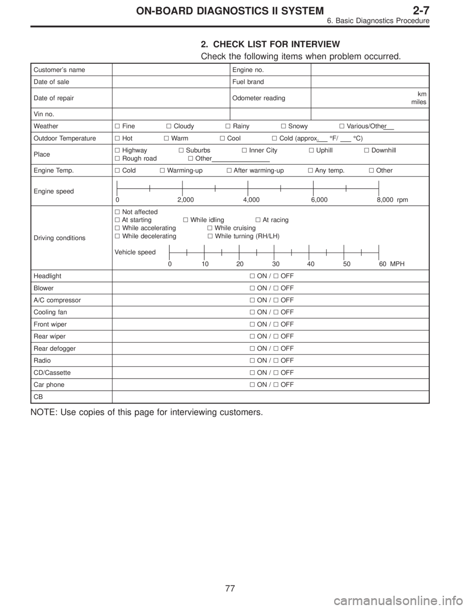
2. CHECK LIST FOR INTERVIEW
Check the following items when problem occurred.
Customer’s name Engine no.
Date of sale Fuel brand
Date of repair Odometer readingkm
miles
Vin no.
Weather�Fine�Cloudy�Rainy�Snowy�Various/Other
Outdoor Temperature�Hot�Warm�Cool�Cold (approx.°F/°C)
Place�Highway�Suburbs�Inner City�Uphill�Downhill
�Rough road�Other
Engine Temp.�Cold�Warming-up�After warming-up�Any temp.�Other
Engine speed
0 2,000 4,000 6,000 8,000 rpm
Driving conditions�Not affected
�At starting�While idling�At racing
�While accelerating�While cruising
�While decelerating�While turning (RH/LH)
Vehicle speed
0 102030405060MPH
Headlight�ON /�OFF
Blower�ON /�OFF
A/C compressor�ON /�OFF
Cooling fan�ON /�OFF
Front wiper�ON /�OFF
Rear wiper�ON /�OFF
Rear defogger�ON /�OFF
Radio�ON /�OFF
CD/Cassette�ON /�OFF
Car phone�ON /�OFF
CB
NOTE: Use copies of this page for interviewing customers.
77
2-7ON-BOARD DIAGNOSTICS II SYSTEM
6. Basic Diagnostics Procedure
Page 1846 of 2890
 Other warning lights or indicators turn on.�Ye s /�No
��
1Low fuel warning light
��
2Charge indicator light
��
3AT diagnosti")
Check the following items about the vehicle’s state when
MIL turns on.
a) Other warning lights or indicators turn on.�Ye s /�No
��
1Low fuel warning light
��
2Charge indicator light
��
3AT diagnostics indicator light
��
4ABS warning light
��
5TCS warning light
��
6Engine oil pressure warning light
b) Fuel level
�Lack of gasoline:�Ye s /�No
�Indicator position of fuel gauge:
c) Intentional connecting or disconnecting of harness connectors or spark plug cords:�Ye s /�No
�What:
d) Intentional connecting or disconnecting of hoses:�Ye s /�No
�What:
e) Installing of parts other than genuine parts�Ye s /�No
�What:
�Where:
f) Occurrence of noise�Ye s /�No
�From where:
�What kind:
g) Occurrence of smell�Ye s /�No
�From where:
�What kind:
h) Intrusion of water into engine compartment or passenger compartment�Ye s /�No
i) Troubles occurred
��
1Engine does not start.
��
2Engine stalls during idling.
��
3Engine stalls while driving.
��
4Engine speed decreases.
��
5Engine speed does not decrease.
��
6Rough idling
��
7Poor acceleration
��
8Back fire
��
9After fire
��
10No shift
��
11Excessive shift shock
NOTE: Use copies of this page for interviewing customers.
78
2-7ON-BOARD DIAGNOSTICS II SYSTEM
6. Basic Diagnostics Procedure
 Measure battery voltage and specific gravity of electro-
lyte.
Standar")