Page 2110 of 2890
 Measure resistance of harness between combination
meter connector and chassis ground.
: Connector & terminal
(i12) No. 1—Chassis ground:
Is resistance less than 5Ω?
: Repair or replace")
B2M0934A
4) Measure resistance of harness between combination
meter connector and chassis ground.
: Connector & terminal
(i12) No. 1—Chassis ground:
Is resistance less than 5Ω?
: Repair or replace combination meter.
: Repair harness and connector.
NOTE:
In this case, repair the following:
�Open circuit in harness between combination meter con-
nector and grounding terminal
�Poor contact in combination meter connector
�Poor contact in grounding terminal
H2M1414B
10BP3CHECK INPUT SIGNAL FOR ECM.
(USING VOLTAGE METER AND SUBARU
SELECT MONITOR.)
1) Turn ignition switch to ON. (Engine OFF)
2) Measure voltage between ECM connector and chassis
ground.
: Connector & terminal
(B84) No. 27 (+)—Chassis ground (�):
Is the voltage more than 4.75 V?
: Go to step10BP4.
: Go to next step 3).
H2M1414B
3) Measure voltage between ECM connector and chassis
ground.
: Connector & terminal
(B84) No. 27 (+)—Chassis ground (�):
Is the voltage less than 0.12 V?
: Go to step10BP9(LHD) or10BP10(RHD).
: Go to next.
342
2-7ON-BOARD DIAGNOSTICS II SYSTEM
10. Diagnostics Chart with Trouble Code
Page 2126 of 2890
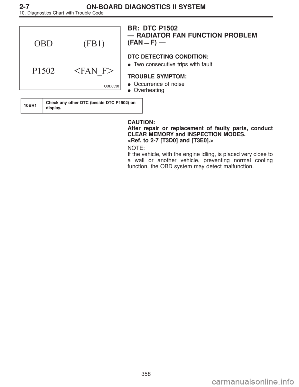
OBD0538
BR: DTC P1502
—RADIATOR FAN FUNCTION PROBLEM
(FAN
—F)—
DTC DETECTING CONDITION:
�Two consecutive trips with fault
TROUBLE SYMPTOM:
�Occurrence of noise
�Overheating
10BR1Check any other DTC (beside DTC P1502) on
display.
CAUTION:
After repair or replacement of faulty parts, conduct
CLEAR MEMORY and INSPECTION MODES.
NOTE:
If the vehicle, with the engine idling, is placed very close to
a wall or another vehicle, preventing normal cooling
function, the OBD system may detect malfunction.
358
2-7ON-BOARD DIAGNOSTICS II SYSTEM
10. Diagnostics Chart with Trouble Code
Page 2128 of 2890
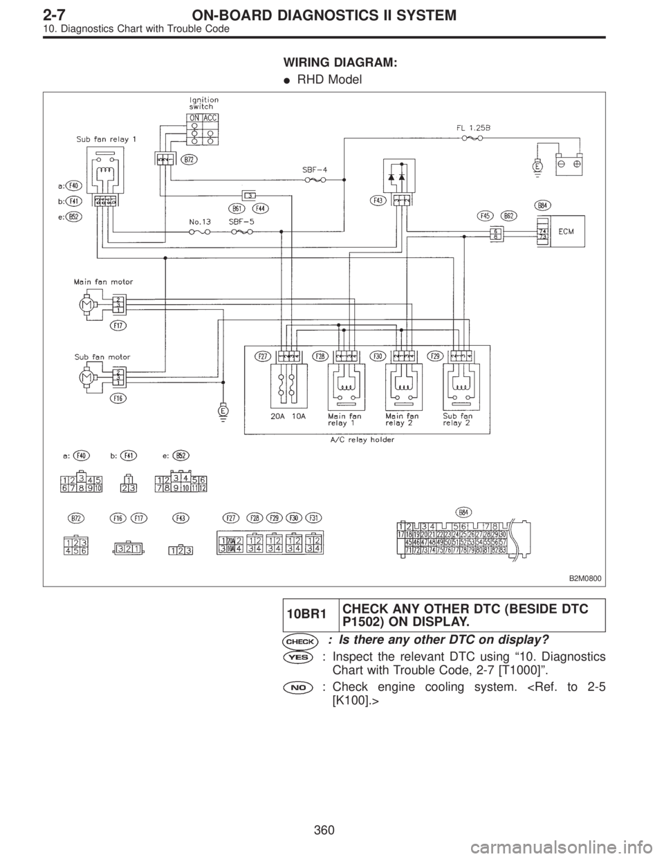
WIRING DIAGRAM:
�RHD Model
B2M0800
10BR1CHECK ANY OTHER DTC (BESIDE DTC
P1502) ON DISPLAY.
: Is there any other DTC on display?
: Inspect the relevant DTC using“10. Diagnostics
Chart with Trouble Code, 2-7 [T1000]”.
: Check engine cooling system.
[K100].>
360
2-7ON-BOARD DIAGNOSTICS II SYSTEM
10. Diagnostics Chart with Trouble Code
Page 2129 of 2890
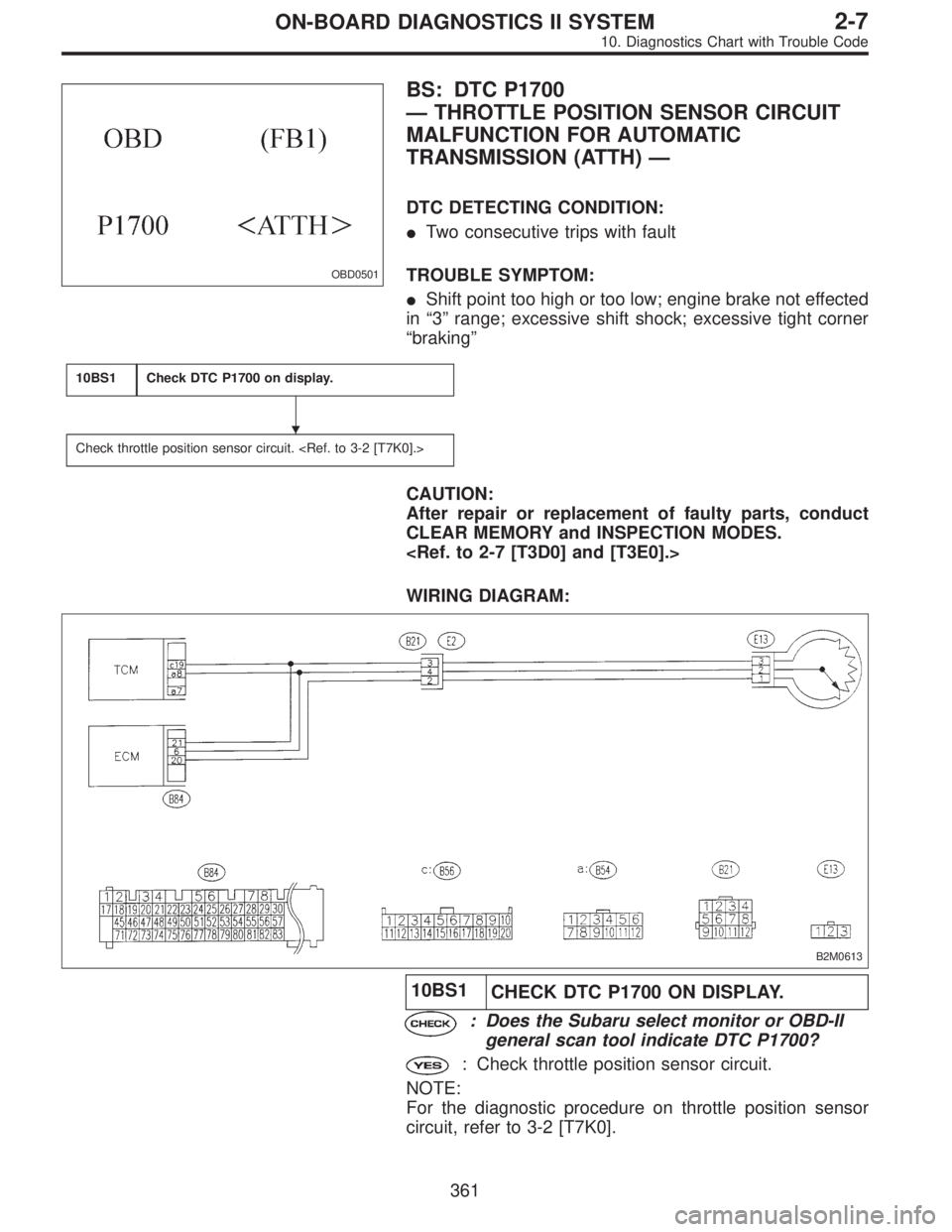
OBD0501
BS: DTC P1700
—THROTTLE POSITION SENSOR CIRCUIT
MALFUNCTION FOR AUTOMATIC
TRANSMISSION (ATTH)—
DTC DETECTING CONDITION:
�Two consecutive trips with fault
TROUBLE SYMPTOM:
�Shift point too high or too low; engine brake not effected
in“3”range; excessive shift shock; excessive tight corner
“braking”
10BS1Check DTC P1700 on display.
Check throttle position sensor circuit.
CAUTION:
After repair or replacement of faulty parts, conduct
CLEAR MEMORY and INSPECTION MODES.
WIRING DIAGRAM:
B2M0613
10BS1
CHECK DTC P1700 ON DISPLAY.
: Does the Subaru select monitor or OBD-II
general scan tool indicate DTC P1700?
: Check throttle position sensor circuit.
NOTE:
For the diagnostic procedure on throttle position sensor
circuit, refer to 3-2 [T7K0].
�
361
2-7ON-BOARD DIAGNOSTICS II SYSTEM
10. Diagnostics Chart with Trouble Code
Page 2132 of 2890
OBD0513A
10BT2
CHECK INPUT SIGNAL FOR TCM.
1) Connect connector to TCM and CCM.
2) Lift-up the vehicle or set the vehicle on free rollers.
CAUTION:
On AWD models, raise all wheels off ground.
3) Start the engine.
4) Cruise control main switch to ON.
5) TCS OFF switch to ON. (with TCS models only)
6) Move selector lever to“D”and slowly increase vehicle
speed to 50 km/h (31 MPH).
7) Cruise control set switch to ON.
8) Measure voltage between TCM and chassis ground.
: Connector & terminal
(B56) No. 3 (+)—Chassis ground (�):
Is the voltage less than 1 V?
: Go to next.
: Check cruise control set circuit.
[T7A0].>
: Is there poor contact in TCM connector?
: Repair poor contact in TCM connector.
: Replace TCM.
364
2-7ON-BOARD DIAGNOSTICS II SYSTEM
10. Diagnostics Chart with Trouble Code
Page 2138 of 2890
BW:—AT/MT IDENTIFICATION CIRCUIT
MALFUNCTION [MT VEHICLES]—
10BW1Check harness between ECM connector and
engine grounding terminal.
CAUTION:
After repair or replacement of faulty parts, conduct
CLEAR MEMORY and INSPECTION MODES.
WIRING DIAGRAM:
B2M0617
370
2-7ON-BOARD DIAGNOSTICS II SYSTEM
10. Diagnostics Chart with Trouble Code
Page 2139 of 2890
B2M0618A
10BW1CHECK HARNESS BETWEEN ECM CON-
NECTOR AND ENGINE GROUNDING
TERMINAL.
1) Turn ignition switch to ON.
2) Measure voltage between ECM and chassis ground.
: Connector & terminal
(B84) No. 81 (+)—Chassis ground (�):
Is the voltage more than 2 V?
: Repair harness and connector.
NOTE:
In this case, repair the following:
�Open circuit in harness between ECM connector and
engine grounding terminal
�Poor contact in engine grounding terminal
�Poor contact in coupling connector (B22)
: Go to next.
: Is there poor contact in ECM connector?
: Repair poor contact in ECM connector.
: Contact with SOA service.
NOTE:
Inspection by DTM is required, because probable cause is
deterioration of multiple parts.
371
2-7ON-BOARD DIAGNOSTICS II SYSTEM
10. Diagnostics Chart with Trouble Code
Page 2142 of 2890
 Check that selector lever does not move from“N”to“R”
without pushing the bu")
G3M0717
3. OPERATION OF SHIFT SELECTOR LEVER
WARNING:
Stop the engine while checking operation of selector
lever.
1) Check that selector lever does not move from“N”to“R”
without pushing the button.
2) Check that selector lever does not move from“R”to“P”
without pushing the button.
3) Check that selector lever does not move from“P”to“R”
without pushing the button.
4) Check that selector lever does not move from“3”to“2”
without pushing the button.
3. Electrical Components Location
1. SENSOR AND CONTROL MODULE
B3M0178B
�1Throttle position sensor
�
2Dropping resistor
�
3Vehicle speed sensor 2
�
4Inhibitor switch
�
5ECM
�
6Vehicle speed sensor 1 (AWD)
�
7Vehicle speed sensor 1 (FWD)
�
8TCM�
9Data link connector (for Subaru select monitor only)
�
10Data link connector (for Subaru select monitor and OBD-II
general scan tool)
�
11Diagnosis connector
�
12Diagnosis terminal
�
13AT OIL TEMP indicator light
(AT diagnostic indicator light)
3
3-2AUTOMATIC TRANSMISSION AND DIFFERENTIAL
2. Pre-inspection - 3. Electrical Components Location
 Connect connector to TCM and CCM.
2) Lift-up the vehicle or set the vehicle on free rollers.
CAUTION:
On AWD models, raise all wheels off ground.
3) Start")
![SUBARU LEGACY 1996 Service Repair Manual BW:—AT/MT IDENTIFICATION CIRCUIT
MALFUNCTION [MT VEHICLES]—
10BW1Check harness between ECM connector and
engine grounding terminal.
CAUTION:
After repair or replacement of faulty parts, conduct
CL](/manual-img/17/57433/w960_57433-2137.png "SUBARU LEGACY 1996 Service Repair Manual BW:—AT/MT IDENTIFICATION CIRCUIT
MALFUNCTION [MT VEHICLES]—
10BW1Check harness between ECM connector and
engine grounding terminal.
CAUTION:
After repair or replacement of faulty parts, conduct
CL")
 Turn ignition switch to ON.
2) Measure voltage between ECM and chassis ground.
: Connector & terminal
(B84) No. 81")