Page 2143 of 2890
G3M0717
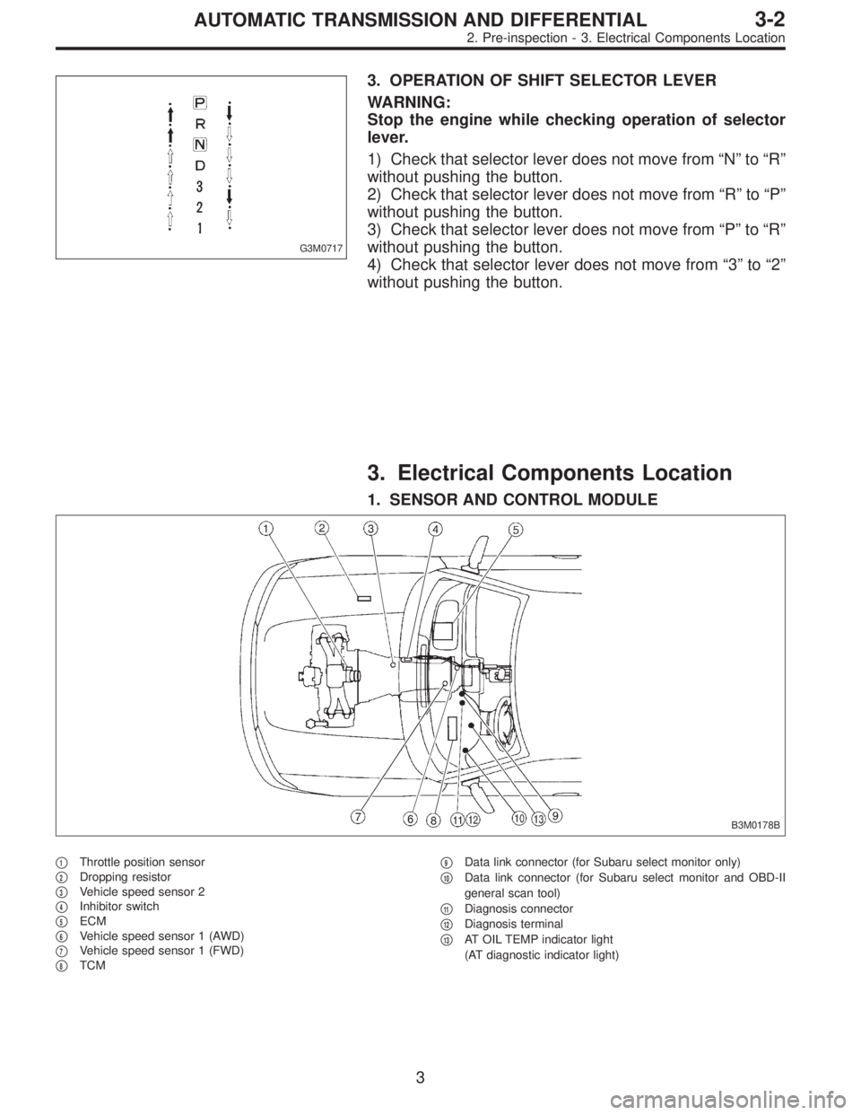
3. OPERATION OF SHIFT SELECTOR LEVER
WARNING:
Stop the engine while checking operation of selector
lever.
1) Check that selector lever does not move from“N”to“R”
without pushing the button.
2) Check that selector lever does not move from“R”to“P”
without pushing the button.
3) Check that selector lever does not move from“P”to“R”
without pushing the button.
4) Check that selector lever does not move from“3”to“2”
without pushing the button.
3. Electrical Components Location
1. SENSOR AND CONTROL MODULE
B3M0178B
�1Throttle position sensor
�
2Dropping resistor
�
3Vehicle speed sensor 2
�
4Inhibitor switch
�
5ECM
�
6Vehicle speed sensor 1 (AWD)
�
7Vehicle speed sensor 1 (FWD)
�
8TCM�
9Data link connector (for Subaru select monitor only)
�
10Data link connector (for Subaru select monitor and OBD-II
general scan tool)
�
11Diagnosis connector
�
12Diagnosis terminal
�
13AT OIL TEMP indicator light
(AT diagnostic indicator light)
3
3-2AUTOMATIC TRANSMISSION AND DIFFERENTIAL
2. Pre-inspection - 3. Electrical Components Location
Page 2148 of 2890
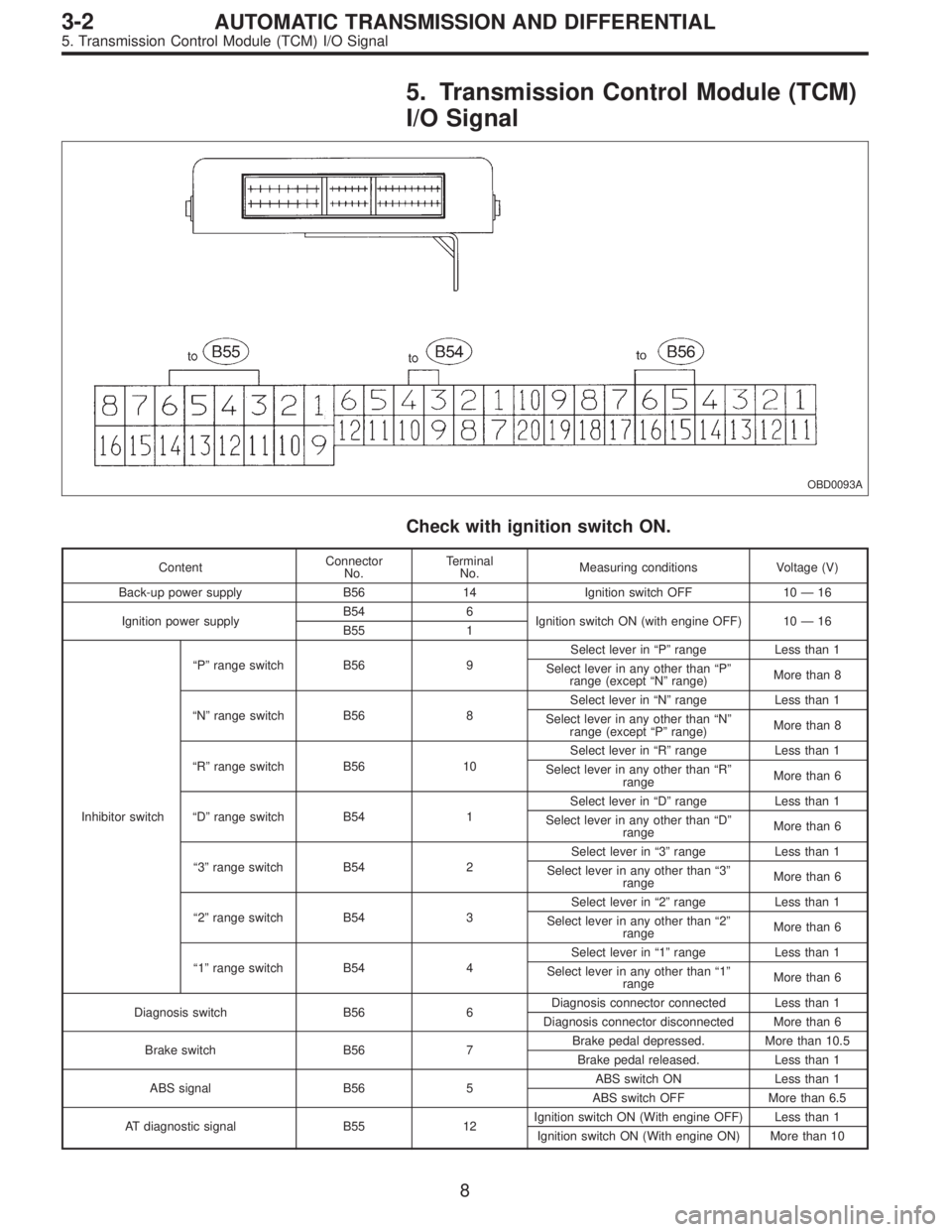
5. Transmission Control Module (TCM)
I/O Signal
OBD0093A
Check with ignition switch ON.
ContentConnector
No.Terminal
No.Measuring conditions Voltage (V)
Back-up power supply B56 14 Ignition switch OFF 10—16
Ignition power supplyB54 6
Ignition switch ON (with engine OFF) 10—16
B55 1
Inhibitor switch“P”range switch B56 9Select lever in“P”range Less than 1
Select lever in any other than“P”
range (except“N”range)More than 8
“N”range switch B56 8Select lever in“N”range Less than 1
Select lever in any other than“N”
range (except“P”range)More than 8
“R”range switch B56 10Select lever in“R”range Less than 1
Select lever in any other than“R”
rangeMore than 6
“D”range switch B54 1Select lever in“D”range Less than 1
Select lever in any other than“D”
rangeMore than 6
“3”range switch B54 2Select lever in“3”range Less than 1
Select lever in any other than“3”
rangeMore than 6
“2”range switch B54 3Select lever in“2”range Less than 1
Select lever in any other than“2”
rangeMore than 6
“1”range switch B54 4Select lever in“1”range Less than 1
Select lever in any other than“1”
rangeMore than 6
Diagnosis switch B56 6Diagnosis connector connected Less than 1
Diagnosis connector disconnected More than 6
Brake switch B56 7Brake pedal depressed. More than 10.5
Brake pedal released. Less than 1
ABS signal B56 5ABS switch ON Less than 1
ABS switch OFF More than 6.5
AT diagnostic signal B55 12Ignition switch ON (With engine OFF) Less than 1
Ignition switch ON (With engine ON) More than 10
8
3-2AUTOMATIC TRANSMISSION AND DIFFERENTIAL
5. Transmission Control Module (TCM) I/O Signal
Page 2151 of 2890
B: ABNORMAL DISPLAY ON AT OIL TEMP
INDICATOR
When any on-board diagnostic item is malfunctioning, the
display on the AT OIL TEMP indicator blinks immediately
after the engine starts.
The malfunctioning part or unit can be determined by a
trouble code during on-board diagnostic operation. Prob-
lems which occurred previously can also be identified
through the memory function.
If the AT OIL TEMP indicator does not show a problem
(although a problem is occurring), the problem can be
determined by checking the performance characteristics of
each sensor using the select monitor.
Indicator signal is as shown in the figure.
WARNING:
Warning can be noticed only when the engine is ini-
tially started.
B3M0410A
11
3-2AUTOMATIC TRANSMISSION AND DIFFERENTIAL
6. Diagnostic Chart for On-board Diagnostic System
Page 2157 of 2890
OBD0432
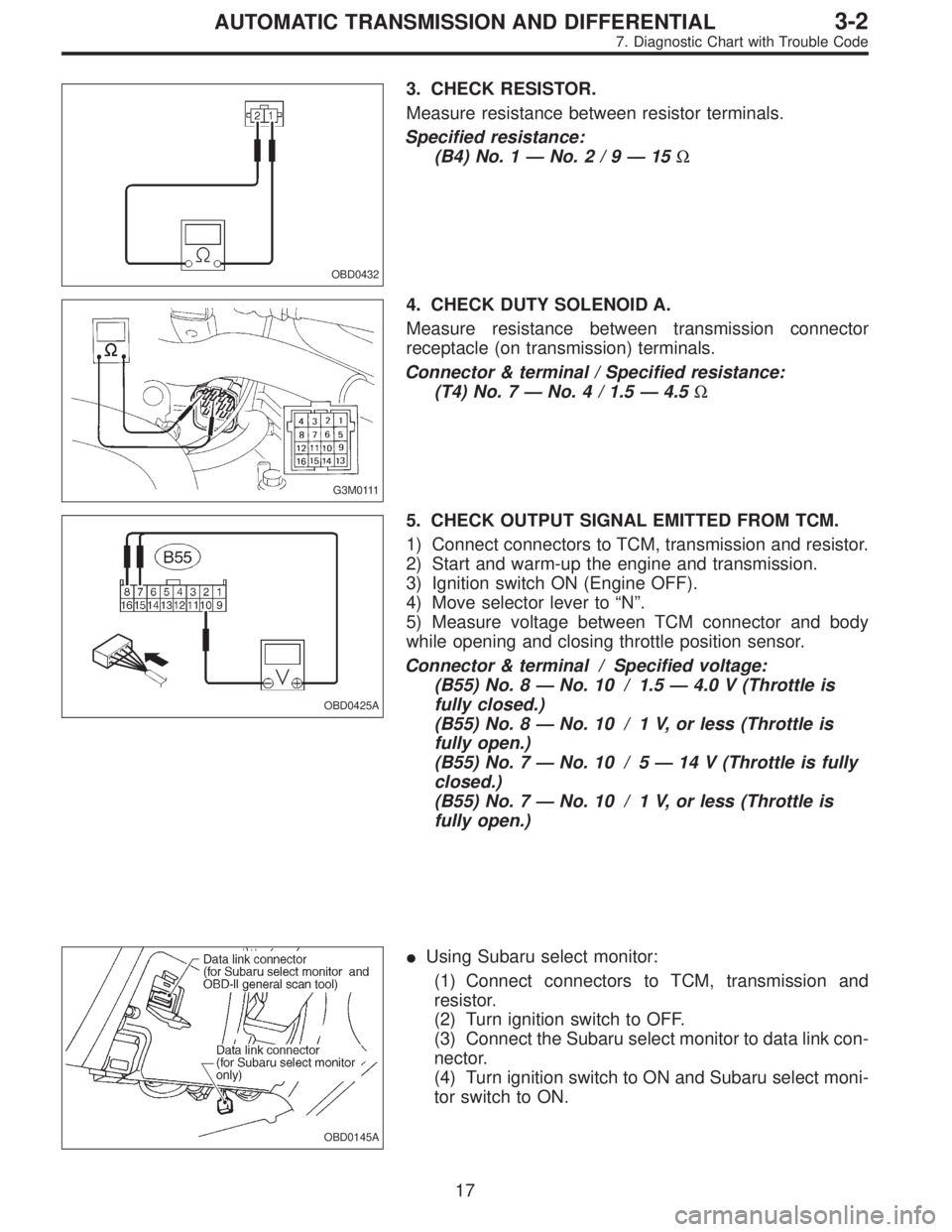
3. CHECK RESISTOR.
Measure resistance between resistor terminals.
Specified resistance:
(B4) No. 1—No.2/9—15Ω
G3M0111
4. CHECK DUTY SOLENOID A.
Measure resistance between transmission connector
receptacle (on transmission) terminals.
Connector & terminal / Specified resistance:
(T4) No. 7—No. 4 / 1.5—4.5Ω
OBD0425A
5. CHECK OUTPUT SIGNAL EMITTED FROM TCM.
1) Connect connectors to TCM, transmission and resistor.
2) Start and warm-up the engine and transmission.
3) Ignition switch ON (Engine OFF).
4) Move selector lever to“N”.
5) Measure voltage between TCM connector and body
while opening and closing throttle position sensor.
Connector & terminal / Specified voltage:
(B55) No. 8—No. 10 / 1.5—4.0 V (Throttle is
fully closed.)
(B55) No. 8—No. 10 / 1 V, or less (Throttle is
fully open.)
(B55) No. 7—No. 10 / 5—14 V (Throttle is fully
closed.)
(B55) No. 7—No. 10 / 1 V, or less (Throttle is
fully open.)
OBD0145A
�Using Subaru select monitor:
(1) Connect connectors to TCM, transmission and
resistor.
(2) Turn ignition switch to OFF.
(3) Connect the Subaru select monitor to data link con-
nector.
(4) Turn ignition switch to ON and Subaru select moni-
tor switch to ON.
17
3-2AUTOMATIC TRANSMISSION AND DIFFERENTIAL
7. Diagnostic Chart with Trouble Code
Page 2159 of 2890
B: TROUBLE CODE 12
—DUTY SOLENOID B—
DIAGNOSIS:
Output signal circuit of duty solenoid B is open or shorted.
TROUBLE SYMPTOM:
No“locking-up”(after engine warm-up)
1. Check harness and connectors between TCM
and duty solenoid B.
OK
�Not OK
Repair or replace harness connectors.
2. Check duty solenoid B’s ground line.
OK
�Not OK
Repair ground line.
3. Check duty solenoid B.
OK
�Not OK
Replace duty solenoid B.
4. Check output signal emitted from TCM.
OK
�Not OK
�Repair TCM connector terminal poor contact.
�Replace TCM.
�Repair TCM connector terminal poor contact.
OBD0413
�
�
�
�
19
3-2AUTOMATIC TRANSMISSION AND DIFFERENTIAL
7. Diagnostic Chart with Trouble Code
Page 2161 of 2890
OBD0607A
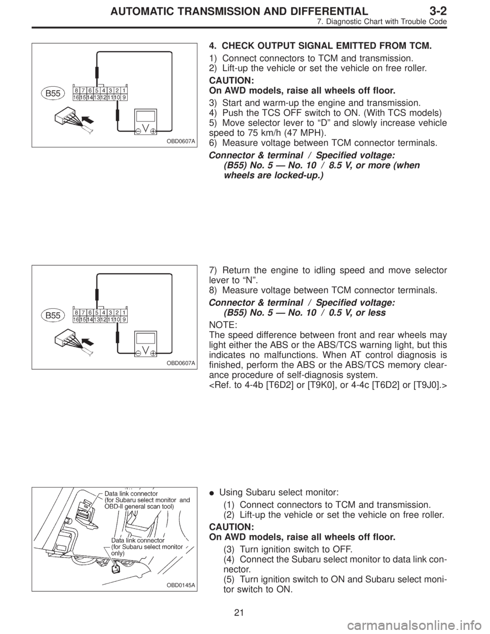
4. CHECK OUTPUT SIGNAL EMITTED FROM TCM.
1) Connect connectors to TCM and transmission.
2) Lift-up the vehicle or set the vehicle on free roller.
CAUTION:
On AWD models, raise all wheels off floor.
3) Start and warm-up the engine and transmission.
4) Push the TCS OFF switch to ON. (With TCS models)
5) Move selector lever to“D”and slowly increase vehicle
speed to 75 km/h (47 MPH).
6) Measure voltage between TCM connector terminals.
Connector & terminal / Specified voltage:
(B55) No. 5—No. 10 / 8.5 V, or more (when
wheels are locked-up.)
OBD0607A
7) Return the engine to idling speed and move selector
lever to“N”.
8) Measure voltage between TCM connector terminals.
Connector & terminal / Specified voltage:
(B55) No. 5—No. 10 / 0.5 V, or less
NOTE:
The speed difference between front and rear wheels may
light either the ABS or the ABS/TCS warning light, but this
indicates no malfunctions. When AT control diagnosis is
finished, perform the ABS or the ABS/TCS memory clear-
ance procedure of self-diagnosis system.
OBD0145A
�Using Subaru select monitor:
(1) Connect connectors to TCM and transmission.
(2) Lift-up the vehicle or set the vehicle on free roller.
CAUTION:
On AWD models, raise all wheels off floor.
(3) Turn ignition switch to OFF.
(4) Connect the Subaru select monitor to data link con-
nector.
(5) Turn ignition switch to ON and Subaru select moni-
tor switch to ON.
21
3-2AUTOMATIC TRANSMISSION AND DIFFERENTIAL
7. Diagnostic Chart with Trouble Code
Page 2163 of 2890
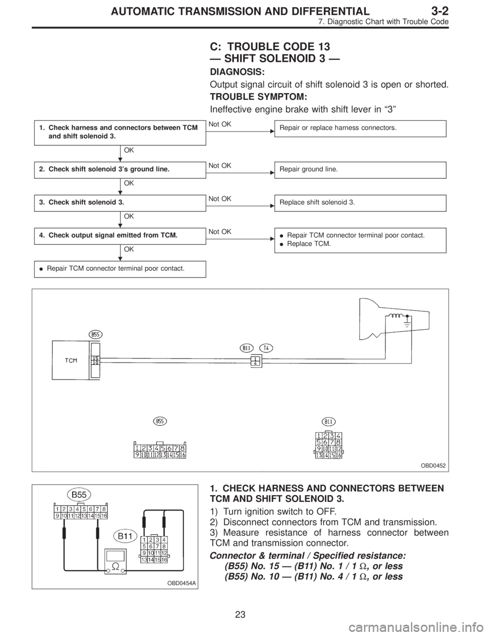
C: TROUBLE CODE 13
—SHIFT SOLENOID 3—
DIAGNOSIS:
Output signal circuit of shift solenoid 3 is open or shorted.
TROUBLE SYMPTOM:
Ineffective engine brake with shift lever in“3”
1. Check harness and connectors between TCM
and shift solenoid 3.
OK
�Not OK
Repair or replace harness connectors.
2. Check shift solenoid 3’s ground line.
OK
�Not OK
Repair ground line.
3. Check shift solenoid 3.
OK
�Not OK
Replace shift solenoid 3.
4. Check output signal emitted from TCM.
OK
�Not OK
�Repair TCM connector terminal poor contact.
�Replace TCM.
�Repair TCM connector terminal poor contact.
OBD0452
OBD0454A
1. CHECK HARNESS AND CONNECTORS BETWEEN
TCM AND SHIFT SOLENOID 3.
1) Turn ignition switch to OFF.
2) Disconnect connectors from TCM and transmission.
3) Measure resistance of harness connector between
TCM and transmission connector.
Connector & terminal / Specified resistance:
(B55) No. 15—(B11)No.1/1Ω, or less
(B55) No. 10—(B11)No.4/1Ω, or less
�
�
�
�
23
3-2AUTOMATIC TRANSMISSION AND DIFFERENTIAL
7. Diagnostic Chart with Trouble Code
Page 2164 of 2890
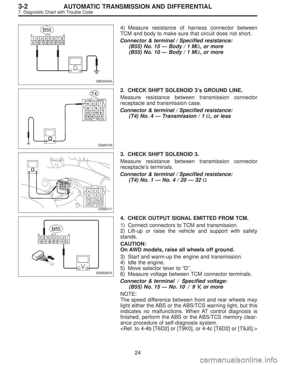
OBD0455A
4) Measure resistance of harness connector between
TCM and body to make sure that circuit does not short.
Connector & terminal / Specified resistance:
(B55) No. 15—Body/1MΩ, or more
(B55) No. 10—Body/1MΩ, or more
G3M0109
2. CHECK SHIFT SOLENOID 3’s GROUND LINE.
Measure resistance between transmission connector
receptacle and transmission case.
Connector & terminal / Specified resistance:
(T4) No. 4—Transmission / 1Ω, or less
G3M0117
3. CHECK SHIFT SOLENOID 3.
Measure resistance between transmission connector
receptacle’s terminals.
Connector & terminal / Specified resistance:
(T4) No. 1—No.4/20—32Ω
B3M0381A
4. CHECK OUTPUT SIGNAL EMITTED FROM TCM.
1) Connect connectors to TCM and transmission.
2) Lift-up or raise the vehicle and support with safety
stands.
CAUTION:
On AWD models, raise all wheels off ground.
3) Start and warm-up the engine and transmission.
4) Idle the engine.
5) Move selector lever to“D”.
6) Measure voltage between TCM connector terminals.
Connector & terminal / Specified voltage:
(B55) No. 15—No. 10 / 9 V, or more
NOTE:
The speed difference between front and rear wheels may
light either the ABS or the ABS/TCS warning light, but this
indicates no malfunctions. When AT control diagnosis is
finished, perform the ABS or the ABS/TCS memory clear-
ance procedure of self-diagnosis system.
24
3-2AUTOMATIC TRANSMISSION AND DIFFERENTIAL
7. Diagnostic Chart with Trouble Code