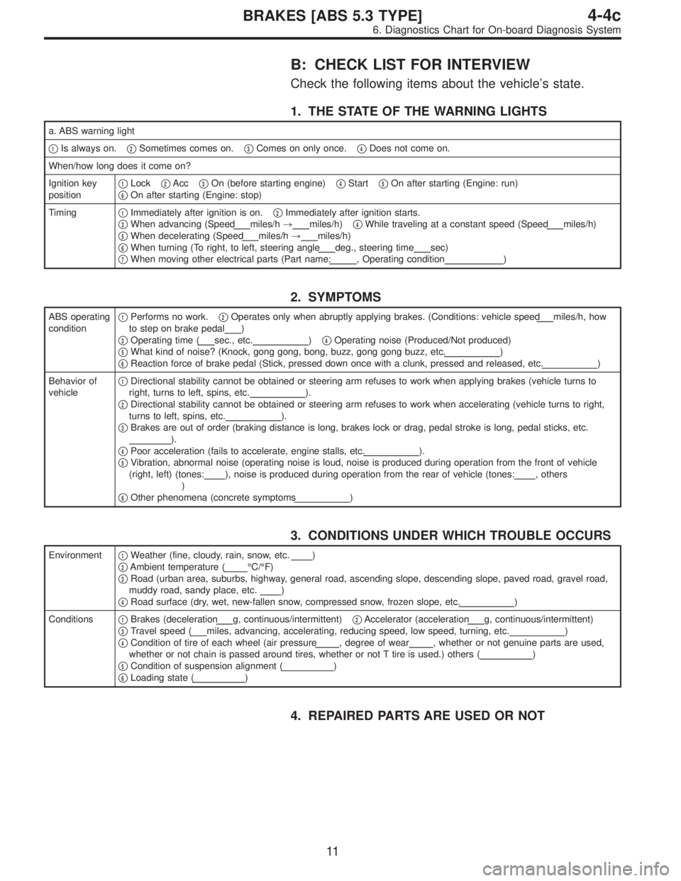
B: CHECK LIST FOR INTERVIEW
Check the following items about the vehicle’s state.
1. THE STATE OF THE WARNING LIGHTS
a. ABS warning light
�
1Is always on.�2Sometimes comes on.�3Comes on only once.�4Does not come on.
When/how long does it come on?
Ignition key
position�
1Lock�2Acc�3On (before starting engine)�4Start�5On after starting (Engine: run)
�
6On after starting (Engine: stop)
Timing�
1Immediately after ignition is on.�2Immediately after ignition starts.
�
3When advancing (Speedmiles/h,miles/h)�4While traveling at a constant speed (Speedmiles/h)
�
5When decelerating (Speedmiles/h,miles/h)
�
6When turning (To right, to left, steering angledeg., steering timesec)
�
7When moving other electrical parts (Part name:, Operating condition)
2. SYMPTOMS
ABS operating
condition�1Performs no work.�2Operates only when abruptly applying brakes. (Conditions: vehicle speedmiles/h, how
to step on brake pedal
)
�
3Operating time (sec., etc.)�4Operating noise (Produced/Not produced)
�
5What kind of noise? (Knock, gong gong, bong, buzz, gong gong buzz, etc.)
�
6Reaction force of brake pedal (Stick, pressed down once with a clunk, pressed and released, etc.)
Behavior of
vehicle�
1Directional stability cannot be obtained or steering arm refuses to work when applying brakes (vehicle turns to
right, turns to left, spins, etc.
).
�
2Directional stability cannot be obtained or steering arm refuses to work when accelerating (vehicle turns to right,
turns to left, spins, etc.
).
�
3Brakes are out of order (braking distance is long, brakes lock or drag, pedal stroke is long, pedal sticks, etc.
).
�
4Poor acceleration (fails to accelerate, engine stalls, etc.).
�
5Vibration, abnormal noise (operating noise is loud, noise is produced during operation from the front of vehicle
(right, left) (tones:
), noise is produced during operation from the rear of vehicle (tones:, others
)
�
6Other phenomena (concrete symptoms)
3. CONDITIONS UNDER WHICH TROUBLE OCCURS
Environment�1Weather (fine, cloudy, rain, snow, etc.)
�
2Ambient temperature (°C/°F)
�
3Road (urban area, suburbs, highway, general road, ascending slope, descending slope, paved road, gravel road,
muddy road, sandy place, etc.
)
�
4Road surface (dry, wet, new-fallen snow, compressed snow, frozen slope, etc.)
Conditions�
1Brakes (decelerationg, continuous/intermittent)�2Accelerator (accelerationg, continuous/intermittent)
�
3Travel speed (miles, advancing, accelerating, reducing speed, low speed, turning, etc.)
�
4Condition of tire of each wheel (air pressure, degree of wear, whether or not genuine parts are used,
whether or not chain is passed around tires, whether or not T tire is used.) others (
)
�
5Condition of suspension alignment ()
�
6Loading state ()
4. REPAIRED PARTS ARE USED OR NOT
11
4-4cBRAKES [ABS 5.3 TYPE]
6. Diagnostics Chart for On-board Diagnosis System