Page 1194 of 2890
Check tie-rod ends, tie-rods and ball
joints of suspension for unsteady
revolution or rattling.
GOOD
�NOT GOOD
Inspect, replace if necessary.
Measure rotating and sliding resistance
of gearbox.
Result: Rotating resistance is 11.18 N
(1.14 kg, 2.51 lb) or less around
center position and 15.79 N
(1.61 kg, 3.55 lb) or less in all
positions within 20% difference
between clockwise and
counterclockwise.
Sliding resistance is 304 N (31
kg, 68 lb) or less with 20%
difference between left and right
directions.�NOT GOOD
Readjust backlash, if ineffective replace
bad parts.
B4M0146
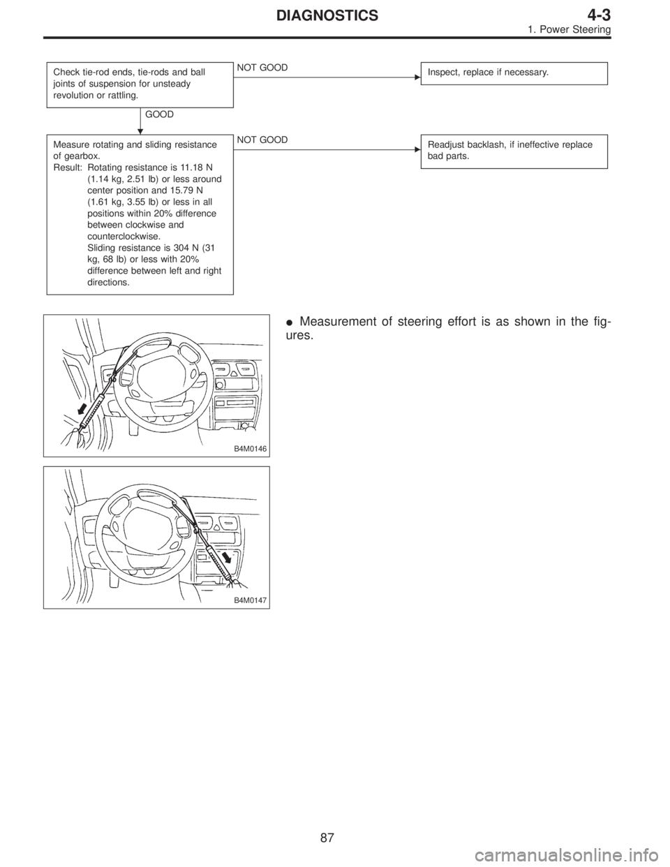
�Measurement of steering effort is as shown in the fig-
ures.
B4M0147
�
87
4-3DIAGNOSTICS
1. Power Steering
Page 1344 of 2890
B: REMOVAL
1. ACCELERATOR PEDAL (LHD MODEL)
1) Disconnect ground cable from battery.
2) Disconnect accelerator cable from throttle body.
CAUTION:
Be careful not to kink accelerator cable.
3) Remove instrument panel lower cover from instrument
panel, and connector.
G4M0322
4) Disconnect accelerator cable from accelerator pedal
lever.
G4M0335
5) Working inside engine compartment, remove casing
cap out of the toe board by turning it clockwise.
6) Pull out the cable from the toe board hole.
G4M0321
7) Remove accelerator pedal connecting bolt from accel-
erator pedal bracket.
8
4-5SERVICE PROCEDURE
1. Pedal
Page 1346 of 2890
4. ACCELERATOR AND BRAKE PEDAL (RHD
MODEL)
1) Disconnect negative cable from battery.
2) Disconnect accelerator cable from throttle body.
CAUTION:
Be careful not to kink accelerator cable.
3) Remove instrument panel lower cover from instrument
panel.
4) Remove clevis pin which secures brake pedal to brake
booster operating rod. Also disconnect electrical connec-
tors (for stop light switch, etc.).
G4M0322
5) Disconnect accelerator cable from accelerator pedal
lever.
B4M0156A
6) Remove the casing cap out of the toe board by turning
it clockwise.
7) Pull out the cable from the toe board hole.
10
4-5SERVICE PROCEDURE
1. Pedal
Page 1353 of 2890
 Disconnect accelerator cable from connector inside
engine compartment first.
G2M0280
2) Remove lock nut from accelerator cable bracket.
3) Separate accelerator cable�
1from bracket, then")
A: REMOVAL
1) Disconnect accelerator cable from connector inside
engine compartment first.
G2M0280
2) Remove lock nut from accelerator cable bracket.
3) Separate accelerator cable�
1from bracket, then unlock
inner cable.
4) Remove cable end from throttle cam using your finger-
tips.
CAUTION:
Be careful not to bend inner cable.
5) Disconnect cable end from accelerator cable bracket
inside driver compartment.
6) Remove clip inside engine compartment.
G4M0335
7) Working inside engine compartment, remove the casing
cap out of the toe board by turning it clockwise.
8) Pull out the cable from the toe board hole.
B: INSTALLATION
1) Installation is in the reverse order of removal proce-
dures.
CAUTION:
�Be careful not to kink accelerator cable.
�Make sure that holder and casing cap are securely
connected.
B4M0159A
�1Casing cap
�
2Accelerator cable
�
3Toe board
�
4Accelerator pedal bracket
�
5Holder
2) Adjustment after cable installation.
17
4-5SERVICE PROCEDURE
3. Accelerator Cable
Page 1373 of 2890
B4M0063
6. Mode Door Motor
A: REMOVAL
1) Remove instrument panel.
2) Remove mode door motor.
B4M0064A
B: INSPECTION
1) When approx. 12 V is applied to the mode door motor
terminals, mode door motor operates as follows:
LHD model
Terminal No.
Mode door motor
21
Polarity of power supply
terminalsMode door motor
operationDirection of linkage
rotation
� + VENT,DEF Clockwise
+� DEF,VENT Counterclockwise
RHD model
Terminal No.
Mode door motor
76
Polarity of power supply
terminalsMode door motor
operationDirection of linkage
rotation
� + VENT,DEF Clockwise
+� DEF,VENT Counterclockwise
2) Check mode door motor position switch.
When the mode door motor is moved to each mode posi-
tion by using the mode selector switch, check if continuity
exists between each terminal as follows:
LHD model
Mode selector switch
positionsTerminal No.
VENT 8 or 7
9 (GND) BI-LEV 6 or 7
HEAT 5or6
DEF/HEAT 4 or 5
DEF 3or4
18
4-6SERVICE PROCEDURE
6. Mode Door Motor
Page 1592 of 2890
H5M0664
6) Disconnect airbag connector on back of airbag module.
Remove airbag module, and place it
with pad side facing upward.
G5M0332
7) Using steering puller, remove steering wheel.
CAUTION:
Do not allow connector to interfere when removing
steering wheel.
B5M0106
8) Remove steering column covers.
9) Removing two retaining screws, remove combination
switch.
B: ADJUSTMENT
1. CENTERING ROLL CONNECTOR
Before installing steering wheel, make sure to center roll
connector built into combination switch.
1) Make sure that front wheels are positioned straight
ahead.
2) Install steering gearbox, steering shaft and combination
switch properly. Turn roll connector pin�
1clockwise until
it stops.
H5M0663A
3) Then, back off roll connector pin�1approximately 2.65
turns until“�”marks aligned.
19
5-5SERVICE PROCEDURE
7. Combination Switch
Page 1613 of 2890
H5M0664
6) Disconnect airbag connector on back of airbag module.
Remove airbag module, and place it
with pad side facing upward.
G5M0332
7) Using steering puller, remove steering wheel.
CAUTION:
Do not allow connector to interfere when removing
steering wheel.
B5M0106
8) Remove steering column covers.
9) Removing two retaining screws, remove combination
switch.
B: ADJUSTMENT
1. CENTERING ROLL CONNECTOR
Before installing steering wheel, make sure to center roll
connector built into combination switch.
1) Make sure that front wheels are positioned straight
ahead.
2) Install steering gearbox, steering shaft and combination
switch properly. Turn roll connector pin�
1clockwiseuntil
it stops.
H5M0663A
3) Then, back off roll connector pin�1approximately 2.65
turns until“�”marks aligned.
17
5-5bSERVICE PROCEDURE
6. Combination Switch
Page 1615 of 2890

1. Engine Electrical
A: SPECIFICATIONS
Item Designation
StarterType Reduction type
ModelMT
TN128000-8311AT
TN128000-8321
Manufacturer NIPPONDENSO TENNESSEE
Voltage and output 12 V — 1.0 kW 12 V — 1.4 kW
Direction of rotation Counterclockwise (when observed from pinion)
Number of pinion teeth 8 9
No-load
characteristicsVoltage 11 V
Current 90 A or less
Rotating
speed3,000 rpm or more 2,900 rpm or more
Load
characteristicsVoltage 8 V
Current 280 A or less 370 A or less
Torque 9.8 N⋅m (1.0 kg-m, 7.2 ft-lb) 13.7 N⋅m (1.4 kg-m, 10.1 ft-lb)
Rotating
speed900 rpm or more 880 rpm or more
Lock
characteristicsVoltage 5 V
Current 800 A or less 1,050 A or less
Torque 27.5 N⋅m (2.8 kg-m, 20.3 ft-lb) or more
GeneratorType Rotating-field three-phase type, Voltage regulator built-in type
Model LR185-701H
Manufacturer HITACHI AUTOMOTIVE PRODUCTS
Voltage and output 12 V — 85 A
Polarity on ground side Negative
Rotating direction Clockwise (when observed from pulley side)
Armature connection 3-phase Y-type
Output current1,500 rpm — 35 A or more
2,500 rpm — 62 A or more
5,000 rpm — 82 A or more
Regulated voltage 14.5
+0.3
�0.4V [20°C (68°F)]
Ignition
coilModel F-569-01R
Manufacturer Diamond
Primary coil resistance 0.69Ω±10%
Secondary coil resistance 21.0 kΩ±15%
Insulation resistance between
primary terminal and caseMore than 10 MΩ
Spark
plugType and manufacturerRC10YC4 .......... CHAMPION
Alternate
(BKR6E-11 .......... NGK
K20PR-U11 .......... NIPPONDENSO)
Thread size mm 14, P = 1.25
Spark gap mm (in) 1.0 — 1.1 (0.039 — 0.043)
2
6-1SPECIFICATIONS AND SERVICE DATA
1. Engine Electrical

1) Disconnect ground cable from battery.
2) Disconnect accelerator cable from throttle body.
CAUTION:
Be careful not to kink accelerator cable.
3) Remove in")

1) Disconnect negative cable from battery.
2) Disconnect accelerator cable from throttle body.
CAUTION:
Be careful not to kink accelerator cable.
3) Remove i")
![SUBARU LEGACY 1996 Service Repair Manual B4M0063
6. Mode Door Motor
A: REMOVAL
1) Remove instrument panel. <Ref. to 5-4 [W1A0].>
2) Remove mode door motor.
B4M0064A
B: INSPECTION
1) When approx. 12 V is applied to the mode door motor
termina](/manual-img/17/57433/w960_57433-1372.png "SUBARU LEGACY 1996 Service Repair Manual B4M0063
6. Mode Door Motor
A: REMOVAL
1) Remove instrument panel. <Ref. to 5-4 [W1A0].>
2) Remove mode door motor.
B4M0064A
B: INSPECTION
1) When approx. 12 V is applied to the mode door motor
termina")
![SUBARU LEGACY 1996 Service Repair Manual H5M0664
6) Disconnect airbag connector on back of airbag module.
<Ref. to 5-5 [M2-6].> Remove airbag module, and place it
with pad side facing upward. <Ref. to 5-5 [W300].>
G5M0332
7) Using steering p](/manual-img/17/57433/w960_57433-1591.png "SUBARU LEGACY 1996 Service Repair Manual H5M0664
6) Disconnect airbag connector on back of airbag module.
<Ref. to 5-5 [M2-6].> Remove airbag module, and place it
with pad side facing upward. <Ref. to 5-5 [W300].>
G5M0332
7) Using steering p")
![SUBARU LEGACY 1996 Service Repair Manual H5M0664
6) Disconnect airbag connector on back of airbag module.
<Ref. to 5-5 [M2-6].> Remove airbag module, and place it
with pad side facing upward. <Ref. to 5-5b [W300].>
G5M0332
7) Using steering](/manual-img/17/57433/w960_57433-1612.png "SUBARU LEGACY 1996 Service Repair Manual H5M0664
6) Disconnect airbag connector on back of airbag module.
<Ref. to 5-5 [M2-6].> Remove airbag module, and place it
with pad side facing upward. <Ref. to 5-5b [W300].>
G5M0332
7) Using steering")