1996 SUBARU LEGACY brake
[x] Cancel search: brakePage 200 of 2890
![SUBARU LEGACY 1996 Service Repair Manual 3-2[T7L0]
AUTOMATIC
TRANSMISSION
AND
DIFFERENTIAL
7
.
Diagnostic
Chart
with
Trouble
Code
1
.
Check
harness
connector
between
TCM
and
throttle
position
sensor
.
OK
2
.
Check
throttle
position
sens SUBARU LEGACY 1996 Service Repair Manual 3-2[T7L0]
AUTOMATIC
TRANSMISSION
AND
DIFFERENTIAL
7
.
Diagnostic
Chart
with
Trouble
Code
1
.
Check
harness
connector
between
TCM
and
throttle
position
sensor
.
OK
2
.
Check
throttle
position
sens](/manual-img/17/57433/w960_57433-199.png)
3-2[T7L0]
AUTOMATIC
TRANSMISSION
AND
DIFFERENTIAL
7
.
Diagnostic
Chart
with
Trouble
Code
1
.
Check
harness
connector
between
TCM
and
throttle
position
sensor
.
OK
2
.
Check
throttle
position
sensor
.
OK
1
3
.
Check
input
signal
for
TCM
.
Not
OK
4
.
Check
power
supply
tothrottle
position
sensor
.
OK
9
Repair
TCM
connector
terminal
poor
contact
.
e
Replace
TCM
.
Not
OK
j
Repair
or
replace
harnessconnectors
.
Not
OK
Replace
throttle
position
sensor
.
OK
~
9
Repair
TCM
connector
terminal
poor
contact
.
-~j9
Replace
TCM
.
Not
OK
,1
Repair
or
replace
harnessconnectors
.
E13
884
B84
112
34
U
56
U
78
U
171819
20
212223
24252627
28
2930
454647
48
49
50515253
1
54
1
55
1
5657
7172
73
74
757677787980
8182
83
L
:
TROUBLE
CODE
31
-
THROTTLE
POSITION
SENSOR
-
DIAGNOSIS
:
Input
signal
circuit
ofthrottle
position
sensor
is
open
or
shorted
.
TROUBLE
SYMPTOM
:
Shift
point
too
high
or
too
low
;
engine
brake
not
effected
in
"3"
range
;
excessive
shift
shock
;
excessive
tight
corner
"braking"
~~B56a~B54
821
E13
1234
12345678910
123456
1314151617181920
789101112
5678
9101112
1
23
1112
B2M0613
10
Page 209 of 2890
![SUBARU LEGACY 1996 Service Repair Manual 3-2
[rsPO]
AUTOMATIC
TRANSMISSION
AND
DIFFERENTIAL
8
.
Diagnostic
Chart
with
Select
Monitor
DISPLAY
LEDNo
.
Signal
name
Symbol
1
FWD
switch
FF
2
Kick-down
switch
KD
3
--
4
--
5
Brake
BR
6
ABS
SUBARU LEGACY 1996 Service Repair Manual 3-2
[rsPO]
AUTOMATIC
TRANSMISSION
AND
DIFFERENTIAL
8
.
Diagnostic
Chart
with
Select
Monitor
DISPLAY
LEDNo
.
Signal
name
Symbol
1
FWD
switch
FF
2
Kick-down
switch
KD
3
--
4
--
5
Brake
BR
6
ABS](/manual-img/17/57433/w960_57433-208.png)
3-2
[rsPO]
AUTOMATIC
TRANSMISSION
AND
DIFFERENTIAL
8
.
Diagnostic
Chart
with
Select
Monitor
DISPLAY
LEDNo
.
Signal
name
Symbol
1
FWD
switch
FF
2
Kick-down
switch
KD
3
--
4
--
5
Brake
BR
6
ABS
switch
AB
7
Cruise
control
set
CR
8
Power
switch
PW
9
-
-
10
t
-
--
I
-
FF
KDBR
ABCR
PW
DDDD
,o
DISPLAY
LEDNo
.
Signal
name
Symbol
1
N/P
range
switch
NP
2
R
range
switch
RR
3
D
range
switch
RD
43
range
switch
R3
5
2
range
switch
R2
6
1
range
switch
R1
7
Diagnosis
switch
SS
--
s
--
,o
_
1
-
NPRRRD
R3
R2
R1
SS
10
P
:
MODE
FAO
-
SWITCH
1
(SW1)
-
Reference
values
"
Lights
up
when
the
fuse
is
installed
in
FWD
switch
(No
.
1)
.
"
Lights
up
when
the
brake
pedal
is
depressed
(No
.
5)
"
Lights
up
when
the
ABS
signal
is
entered
(No
.
6)
.
"
Lights
up
when
the
cruise
control
is
set
(No
.
7)
.
NOTE
:
LED
Nos
.
2
and
8
do
not
come
on
.
Q
:
MODE
FA1
-
SWITCH
2
(SW2)
-
Reference
values
"
Lights
up
when
the
N
or
P
range
is
selected
(No
.
1)
.
"
Lights
up
when
the
R
range
is
selected
(No
.
2)
.
"
Lights
up
when
the
D
range
is
selected
(No
.
3)
.
"
Lights
up
when
the
3
range
is
selected
(No
.
4)
.
"
Lights
up
when
the
2
range
is
selected
(No
.
5)
.
"
Lights
up
when
the
1
range
is
selected
(No
.
6)
.
"
Lights
up
when
the
diagnosis
switch
is
connected
(No
.
7)
.
NOTE
:
If
each
LED
does
not
illuminate
in
the
above
conditions,
inhibitor
switch
malfunction
may
occur
.
Performdiagnos-
tics
on
inhibitor
switch
.
<
Ref
.
to
2-7
[T10AN0]
.*2
>
20
Page 220 of 2890
![SUBARU LEGACY 1996 Service Repair Manual
ON-BOARD
DIAGNOSTICS
11
SYSTEM
[T10A0]
2-7
10
.
Diagnostics
Chart
with
Trouble
Code
DTC
No
.
Abbreviation
(Subaru
select
monitor)Item
Page
P0500
VSP
Vehicle
speed
sensor
malfunction
1
P0505
I SUBARU LEGACY 1996 Service Repair Manual
ON-BOARD
DIAGNOSTICS
11
SYSTEM
[T10A0]
2-7
10
.
Diagnostics
Chart
with
Trouble
Code
DTC
No
.
Abbreviation
(Subaru
select
monitor)Item
Page
P0500
VSP
Vehicle
speed
sensor
malfunction
1
P0505
I](/manual-img/17/57433/w960_57433-219.png)
ON-BOARD
DIAGNOSTICS
11
SYSTEM
[T10A0]
2-7
10
.
Diagnostics
Chart
with
Trouble
Code
DTC
No
.
Abbreviation
(Subaru
select
monitor)Item
Page
P0500
VSP
Vehicle
speed
sensor
malfunction
'1
P0505
ISC
Idle
control
system
malfunction
`1
P0506
ISC
-
L
Idle
control
system
RPM
lower
than
expected
'1
P0507
ISC
-
H
Idle
control
system
RPM
higher
than
expected
'1
P0600
-
Serial
communication
link
malfunction
`1
P0601
RAM
Internal
control
module
memory
check
sum
error
'1
P0703
ATBRK
Brake
switch
input
malfunction
'1
P0705
ATRNG
Transmissionrange
sensor
circuit
malfunction
`1
P0710
ATF
Transmission
fluid
temperature
sensor
circuit
malfunction
'1
P0720
ATVSP
Output
speed
sensor
(vehicle
speed
sensor
1)
circuit
malfunction
'1
P0725
ATNE
Engine
speed
input
circuit
malfunction
'1
P0731
ATGR1
Gear
1
incorrect
ratio
P0732
ATGR2
Gear
2
incorrect
ratio
"
1
P0733
ATGR3
Gear
3
incorrect
ratio
P0734
ATGR4
Gear
4
incorrect
ratio
P0740
ATLU
-
F
Torque
converter
clutch
system
malfunction
1
P0743
ATLU
Torque
converter
clutch
system
electrical
*1
P0748
ATPL
Pressure
control
solenoid
electrical
'1
P0753
ATSFTi
Shift
solenoid
A
electrical
`1
P0758
ATSFT2
Shift
solenoid
B
electrical
'1
P0760
ATOVR
-
F
Shift
solenoid
C
malfunction
'1
P0763
ATOVR
Shift
solenoid
C
electrical
'1
P1100
ST-SW
Starter
switch
circuit
malfunction
'1
P1101
N/P
-
SW
Neutral
position
switch
circuit
malfunction
[MT
vehicles]
'1
P1101
N/P
-
SW
Neutral
position
switch
circuit
malfunction
[AT
vehicles]
1
P1102
BR
Pressure
sources
switching
solenoid
valve
circuit
malfunction
'1
P1103
TRQ
Engine
torque
control
signal
circuit
malfunction
`1
P1400
PCVSOL
Fueltank
pressure
control
solenoid
valve
circuit
malfunction
38
P1401
PCV
-
FFueltank
pressure
control
system
function
problem
44
P1402
FIVL
Fuel
level
sensor
circuit
malfunction
46
P1500
FAN
-
1
Radiator
fan
relay
1
circuit
malfunction
'1
P1502
FAN
-
F
Radiator
fan
function
problem
'1
P1700
ATTH
Throttle
position
sensor
circuit
malfunction
for
automatic
transmission
'1
P1701
ATCRS
Cruise
control
set
signal
circuit
malfunction
for
automatic
transmission
'1
P1702
ATDIAG
Automatic
transmission
diagnosis
inputsignal
circuit
malfunction
'1
P0461'2
EXERR22
Fuel
level
sensor
circuit
range/performance
problem
56
"1
:
<
Ref
.
to
2-7
[T11A0]
.*4
>
'2
:
Only
OBD-II
general
scan
tool
displays
DTC
.
Page 268 of 2890
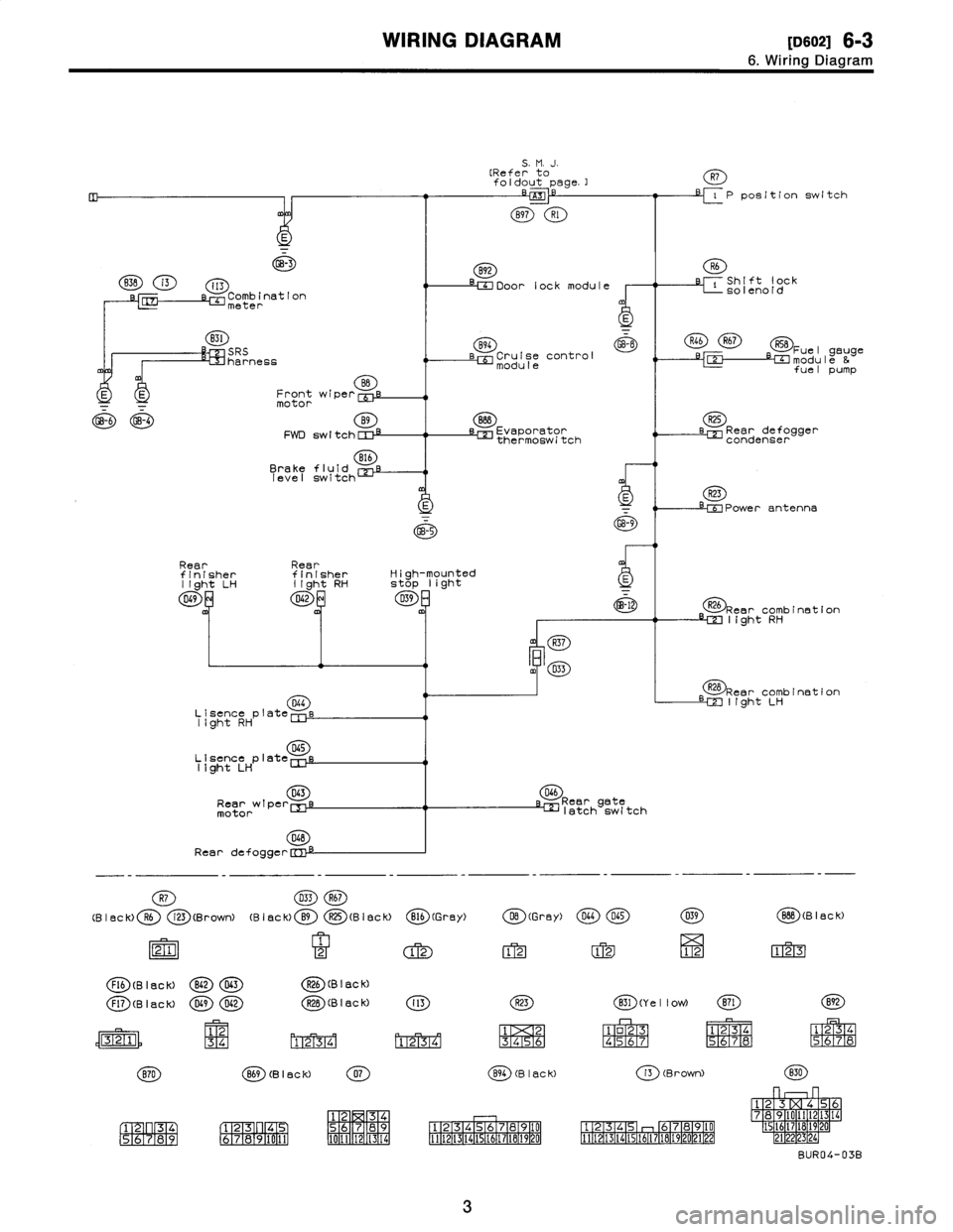
WIRING
DIAGRAM
[oso2i
6-3
6
.
Wiring
Diagram
GB-3
B3B
i3
i13
Comb
ination
'L~J
meter
B31
SRS
harness
BB
E
E
Frontwiper
[Uf
motor
4-6
GB-4
B9
FWD
sw
I
tch
CI
:~
816
Brakefluid
level
switch
Rear
Rear
finisherfinisher
light
LH
light
RH
049
8
D42
D4G
Lisence
plate
Iight
RH
D45
Lisence
plate
11ght
LH
043
Rearwipe
r
motor
048
Rear
defogge
r
R26
Rear
combination
LM
light
RH
R28
Rear
combination
LM
I(ght
LH
D46
Reargate
klatch
switch
R7
033R67
(B
I
ac
k)R6
i23
(BrowN
(B
I
ec
k)
B9
R25
(B
I
ec
k)
B16
(G
rey)
DB
(Gray)
D44045
21
2
12
1212
FI6
(B
I
ac
k)
B62D63R26
(B
I
ac
k)
039
12
BBB
(Black)
123
Fl7
(B
I
ac
k)
D49D42R2B
(B
I
ac
k)
(K)
(Y
e
11
ow)
(E)(9)
12
34
M1_2T3741
13141516
1
o23
N4
;5677
1
234
1
234
5
M67
8
R56
;7iR8
(B
I
8C
k)
(B
I
ac
K)
(Brown)
P
3141
56
789
1
F273
F1
4
6789
0151
7
89
1
2
34
161
2
314
0
1121314E
69
7181
1
11
1
12
1
314
51617
A
920
12
11112
314(51617
B4
02122
78
I
F1
34
161718
212223py
56
2~14
BUR04-03B
5
.
M
.
J
.
[Referto
foldout
page
.]
-
-
z~
B97
Rl
B92
Door
lock
module
B94
GB-8
Cruise
control
module
888
L=]
Evaporator
thermoswitch
R7
P
position
switch
R6
C
Shift
lock
solenoid
R46R67R58
Fuel
gauge
-e-C~umodule
&
fuel
pump
R25
LEE
Reardefogger
condenser
R23
-riPower
antenna
s1
-
~_5
GB-9
High-mounted
stop
light
D39
-12
m
R37
m4
D33
3
Page 275 of 2890
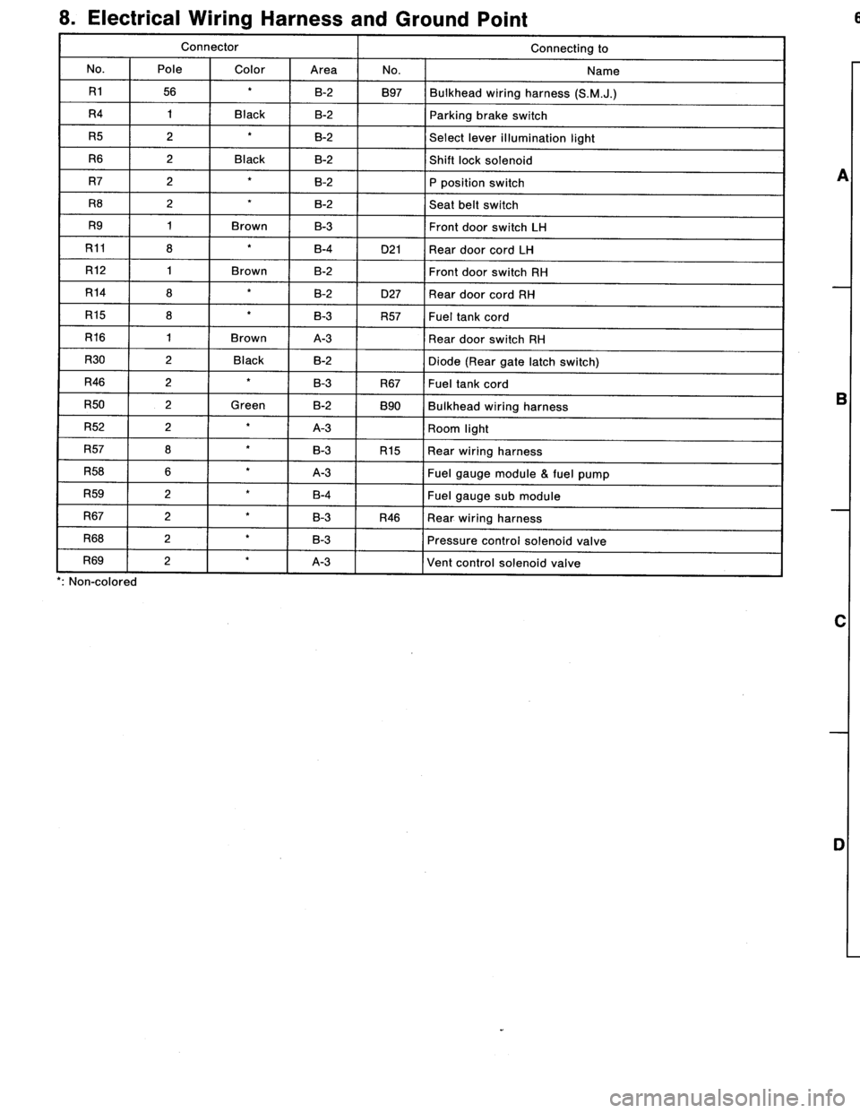
8
.
Electrical
Wiring
Harness
and
Ground
Point
Connector
Connecting
to
No
.
Pole
Color
Area
No
.
Name
R156
B-2
B97
Bulkhead
wiring
harness
(S
.M
.J
.)
R4
1
Black
B-2
Parking
brake
switch
R5
2B-2
Select
lever
illumination
light
R6
2
Black
B-2
Shift
lock
solenoid
R7
2B-2P
position
switch
RS
2B-2
Seat
belt
switch
R9
1
Brown
B-3Front
door
switch
LH
R11
8
B-4D21
Rear
doorcord
LH
R12
1
Brown
B-2
Front
door
switch
RH
R14
8
B-2
D27
Rear
door
cord
RH
R15
8B-3
R57
Fueltank
cord
R16
1
Brown
A-3
Rear
door
switch
RH
R30
2
Black
B-2
Diode
(Rear
gale
latch
switch)
R46
2
B3
R67
Fuel
lankcord
R50
2
Green
B-2
890
Bulkhead
wiring
harness
R52
2
A-3
Room
light
R57
S
B-3
R15
Rear
wiring
harness
R58
6
A-3
Fuel
gaugemodule
&
fuel
pump
R59
2
B-4
Fuel
gauge
submodule
R67
2
B-3
R46
Rear
wiring
harness
R68
2B-3
Pressure
control
solenoid
valve
R69
I
2
A-3
Vent
control
solenoid
valve
non-coiorea
A
B
C
n
6
.
REAR
WIRING
HARNESS
AND
GROUND
POINT
1
I
2
I
3
I
4
2
~S
4
[D806]
B6M0695A
A
B
C
u
Page 276 of 2890
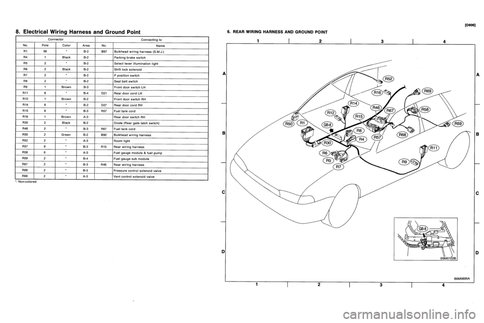
8
.
Electrical
Wiring
Harness
and
Ground
Point
Connector
Connecting
to
No
.
Pole
Color
Area
No
.
Name
R156
B-2
B97
Bulkhead
wiring
harness
(S
.M
.J
.)
R4
1
Black
B-2
Parking
brake
switch
R5
2B-2
Select
lever
illumination
light
R6
2
Black
B-2
Shift
lock
solenoid
R7
2B-2P
position
switch
RS
2B-2
Seat
belt
switch
R9
1
Brown
B-3Front
door
switch
LH
R11
8
B-4D21
Rear
doorcord
LH
R12
1
Brown
B-2
Front
door
switch
RH
R14
8
B-2
D27
Rear
door
cord
RH
R15
8B-3
R57
Fueltank
cord
R16
1
Brown
A-3
Rear
door
switch
RH
R30
2
Black
B-2
Diode
(Rear
gale
latch
switch)
R46
2
B3
R67
Fuel
lankcord
R50
2
Green
B-2
890
Bulkhead
wiring
harness
R52
2
A-3
Room
light
R57
S
B-3
R15
Rear
wiring
harness
R58
6
A-3
Fuel
gaugemodule
&
fuel
pump
R59
2
B-4
Fuel
gauge
submodule
R67
2
B-3
R46
Rear
wiring
harness
R68
2B-3
Pressure
control
solenoid
valve
R69
I
2
A-3
Vent
control
solenoid
valve
non-coiorea
A
B
C
n
6
.
REAR
WIRING
HARNESS
AND
GROUND
POINT
1
I
2
I
3
I
4
2
~S
4
[D806]
B6M0695A
A
B
C
u
Page 307 of 2890
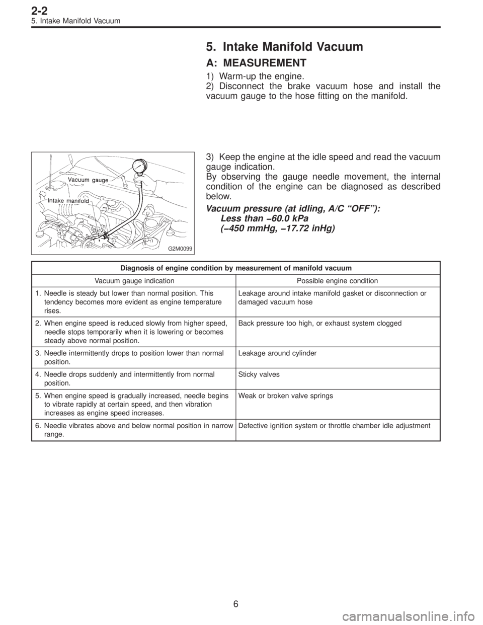
5. Intake Manifold Vacuum
A: MEASUREMENT
1) Warm-up the engine.
2) Disconnect the brake vacuum hose and install the
vacuum gauge to the hose fitting on the manifold.
G2M0099
3) Keep the engine at the idle speed and read the vacuum
gauge indication.
By observing the gauge needle movement, the internal
condition of the engine can be diagnosed as described
below.
Vacuum pressure (at idling, A/C“OFF”):
Less than �60.0 kPa
(�450 mmHg, �17.72 inHg)
Diagnosis of engine condition by measurement of manifold vacuum
Vacuum gauge indication Possible engine condition
1. Needle is steady but lower than normal position. This
tendency becomes more evident as engine temperature
rises.Leakage around intake manifold gasket or disconnection or
damaged vacuum hose
2. When engine speed is reduced slowly from higher speed,
needle stops temporarily when it is lowering or becomes
steady above normal position.Back pressure too high, or exhaust system clogged
3. Needle intermittently drops to position lower than normal
position.Leakage around cylinder
4. Needle drops suddenly and intermittently from normal
position.Sticky valves
5. When engine speed is gradually increased, needle begins
to vibrate rapidly at certain speed, and then vibration
increases as engine speed increases.Weak or broken valve springs
6. Needle vibrates above and below normal position in narrow
range.Defective ignition system or throttle chamber idle adjustment
6
2-2
5. Intake Manifold Vacuum
Page 503 of 2890
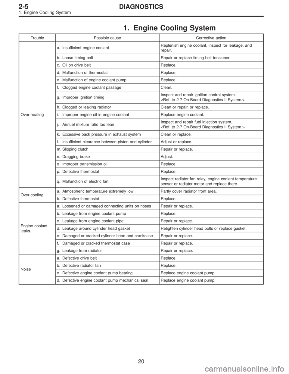
1. Engine Cooling System
Trouble Possible cause Corrective action
Over-heatinga. Insufficient engine coolantReplenish engine coolant, inspect for leakage, and
repair.
b. Loose timing belt Repair or replace timing belt tensioner.
c. Oil on drive belt Replace.
d. Malfunction of thermostat Replace.
e. Malfunction of engine coolant pump Replace.
f. Clogged engine coolant passage Clean.
g. Improper ignition timingInspect and repair ignition control system.
h. Clogged or leaking radiator Clean or repair, or replace.
i. Improper engine oil in engine coolant Replace engine coolant.
j. Air/fuel mixture ratio too leanInspect and repair fuel injection system.
k. Excessive back pressure in exhaust system Clean or replace.
l. Insufficient clearance between piston and cylinder Adjust or replace.
m. Slipping clutch Repair or replace.
n. Dragging brake Adjust.
o. Improper transmission oil Replace.
p. Defective thermostat Replace.
q. Malfunction of electric fanInspect radiator fan relay, engine coolant temperature
sensor or radiator motor and replace there.
Over-coolinga. Atmospheric temperature extremely low Partly cover radiator front area.
b. Defective thermostat Replace.
Engine coolant
leaks.a. Loosened or damaged connecting units on hoses Repair or replace.
b. Leakage from engine coolant pump Replace.
c. Leakage from engine coolant pipe Repair or replace.
d. Leakage around cylinder head gasket Retighten cylinder head bolts or replace gasket.
e. Damaged or cracked cylinder head and crankcase Repair or replace.
f. Damaged or cracked thermostat case Repair or replace.
g. Leakage from radiator Repair or replace.
Noisea. Defective drive belt Replace.
b. Defective radiator fan Replace.
c. Defective engine coolant pump bearing Replace engine coolant pump.
d. Defective engine coolant pump mechanical seal Replace engine coolant pump.
20
2-5DIAGNOSTICS
1. Engine Cooling System