1996 SUBARU LEGACY brake
[x] Cancel search: brakePage 125 of 2890
![SUBARU LEGACY 1996 Service Repair Manual 2-7
[T11AV0]
ON-BOARD
DIAGNOSTICS
11
SYSTEM
11
.
Diagnostics
Chart
with
Trouble
Code
AV
:
DTC
P0740
-
TORQUE
CONVERTER
CLUTCH
SYSTEM
MALFUNCTION
(ATLU
-
F)
-
WIRING
DIAGRAM
:
Automatic
transmiss SUBARU LEGACY 1996 Service Repair Manual 2-7
[T11AV0]
ON-BOARD
DIAGNOSTICS
11
SYSTEM
11
.
Diagnostics
Chart
with
Trouble
Code
AV
:
DTC
P0740
-
TORQUE
CONVERTER
CLUTCH
SYSTEM
MALFUNCTION
(ATLU
-
F)
-
WIRING
DIAGRAM
:
Automatic
transmiss](/manual-img/17/57433/w960_57433-124.png)
2-7
[T11AV0]
ON-BOARD
DIAGNOSTICS
11
SYSTEM
11
.
Diagnostics
Chart
with
Trouble
Code
AV
:
DTC
P0740
-
TORQUE
CONVERTER
CLUTCH
SYSTEM
MALFUNCTION
(ATLU
-
F)
-
WIRING
DIAGRAM
:
Automatic
transmission
Duty
ATF
Vehicle
solenoid
temperature
speed
B
sensor
sensorl
854
Brake
Throttle
b~
B55
1
Ii
t
positions
856
B11
T4
B53
TCM
Inhibitor
switch
N
00
0
a
t
~
3
1
B12
T3
Combination
meter
Speedometer
ECM
circuit
B84
e
:
B54
b
:
855
c
:
B56BI1B53812
O
123456
123456712345678910
81
1
234
5
67
8
9101112
1234
5678
910
11
12
13141516
3132
33
3435
363738394
0
4142
4344
6970
58596061626364L
111
9
1
10
1
11
1
12
1
13
1
14
1
15
11
6
789
101112
1
11
1
12
1
13
1
14
1
15
1
16
1
171819
20
1314
I
I6
1
2349
10
1112
8485
86
87888990
91
E3
1
0
-
4
1
95
96
12
B2M0587
NOTE
:
For
the
diagnostic
procedure
on
torque
converter
clutch
system
malfunction
(DTC
P0740),
referto
2-7
[T10AV0]*2
.
114
Page 175 of 2890
![SUBARU LEGACY 1996 Service Repair Manual
s-$
[D601]
WIRING
DIAGRAM
6
.
Wiring
Diagram
No
.
Load
MB-2
Powerwindow
circuit
breaker
Engine
control
module
Fuel
pump
relay
MB-3
Main
relay
OBD-II
service
connector
MB-4A/C
relay
holder
MB- SUBARU LEGACY 1996 Service Repair Manual
s-$
[D601]
WIRING
DIAGRAM
6
.
Wiring
Diagram
No
.
Load
MB-2
Powerwindow
circuit
breaker
Engine
control
module
Fuel
pump
relay
MB-3
Main
relay
OBD-II
service
connector
MB-4A/C
relay
holder
MB-](/manual-img/17/57433/w960_57433-174.png)
s-$
[D601]
WIRING
DIAGRAM
6
.
Wiring
Diagram
No
.
Load
MB-2
Powerwindow
circuit
breaker
Engine
control
module
Fuel
pump
relay
MB-3
Main
relay
OBD-II
service
connector
MB-4A/C
relay
holder
MB-6
Headlight
LH
Diode
(Lighting)
Lighting
switch
Combination
meter
M
B_$
Headlight
RH
Combination
meter
Door
lock
timer
MB-9
Luggage
room
light
Radio
Room
light
MB-10
A/C
relay
holder
ALT-1
Combination
meter
IG
A/C
relay
holder
Cruise
control
module
ST
Engine
control
module
Inhibitor
switch
FB-2
Diode
(A/C)
Sub
fan
motor
FB-3
Sub
fan
relay-2
Engine
control
module
Fuel
pump
relay
FB-4
Ignition
coil
Transmission
control
module
Side
marker
light
LH
FB-6
Side
marker
light
RH
FB-7Door
lock
timer
FB-9Hazard
switch
AT
shift
lock
control
module
FB-10
Key
warning
switch
Power
antenna
FB-11
Radio
FB-12
Cigarette
lighter
FB-13
Remote
control
rearview
mirrorswitch
AT
shift
lock
control
module
Combination
switch
Front
washer
motor
FB-14
Front
wipermotor
Rear
washer
motor
Rear
wipermotor
Rear
wiper
relay
FB-15Transmission
control
module
Na
Load
Rear
defogger
FB-16
Rear
defogger
condenser
Reardefogger
switch
FB-17
Rear
defogger
switch
FB-18
AT
shift
lock
control
module
Inhibitor
switch
FB-19
Hazard
switch
Combination
meter
FB-20
Mode
control
panel
FB-21
Combination
meter
(Airbag)
Blower
motor
relay
Check
connector
FB-22
FRESH/RECIRC
actuator
Mode
actuator
Powerwindow
relay
Seat
belt
timer
FB-23
Airbag
.
control
module
FB-24
Airbag
control
module
FB-25
Lighting
switch
FB-26
Parking
switch
FB-27
Parking
switch
FB-28
Illumination
light
FB-29
Illumination
light
FB-30
Stop
light
switch
Stop
&
brake
switch
FB-31
Horn
relay
FB-32
Blower
motor
relay
FB-33
Parking
switch
License
plate
light
LH
License
plate
light
RH
FB-34
Rear
combination
light
LH
Rear
combination
light
RH
Rear
finisher
light
LH
Rear
finisher
light
RH
FB-35
Cruise
control
main
switch
Cruise
control
module
Page 177 of 2890
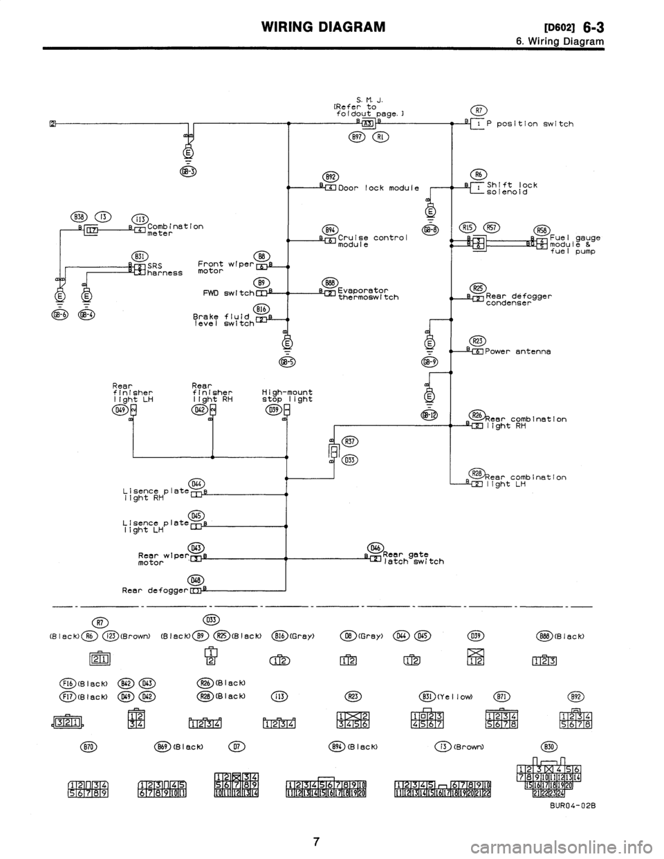
WIRING
DIAGRAM
[oso2i
6-3
6
.
Wiring
Diagram
GB-3
838
13
i13
s-r,
Comb
inationmeter
831
O
SRS
Front
wiper
cui
harness
motor
B9
E
E
FWD
switchCIll
GB-6
GB-4
Brake
fluid
B
CE
level
switch
S
.
M
.
J
.
(Refer
to
foldout
page
.]
B97
Rl
892
IM
Door
lock
module
R7
-71P
position
switch
i
Shift
lock
-
solenoid
B94
~
R~5
R57
RSB
Cruise
control
Fuel
gauge
modulemodule
&
fuel
pump
Evaporator
~z
thermoswltch
Rear
defogger
condenser
R23
-
e
Power
antenna
GB-5GB-9
Rear
Rearfinisher
finisher
High-mount
light
LH
light
RHStop
light
D69042D39
-
~-l
R26
car
combination
m
light
RH
R37
m4
0~3
Lisence
plat
044
e
light
RH
D45
Llsence
plate
light
LH
043
Rear
wtperEnj
motor
D4B
Rear
defogge
r
D46
Reargete
latch
switch
tear
combination
light
LH
-
-
-
-
-
-
-
-
-
-
-
-
-
-
-
-
R7
D33
(Black)
R6
i23
(Brown)(Black)
B9
O(Black)
816
(G
rey)
O(Gray)
DL4D65X39
88B
(B18ck)
21
2
12
12
1212
123
Flb
(B
I
ac
k)
B62D63R26
(B
I
8C
k)
F17
(g
I
flc
k)
DG9042R2B
(B
I
ac
k)
i
13
R23
X31
(Ye
II
ow)
(E)
1
2
34
riT2
ri-r2
m34
131415161
o23
R45
67
1
234
1
234
S
M67
8
P567
N8
(B
I
ac
k)
07
894
(B
I
ac
k)i3
(Brown)
830
1
2
34
1
23
4
67
89
1
12
4
78910
1
1
7891
7
23
L
5
16
89
2211171
4
112131
19
0
6
141
6789
67891
1
1
112(3(
111
l
141
1617LB19
t
12114
1
1611
192
p1
BUR04-02B
7
Page 188 of 2890
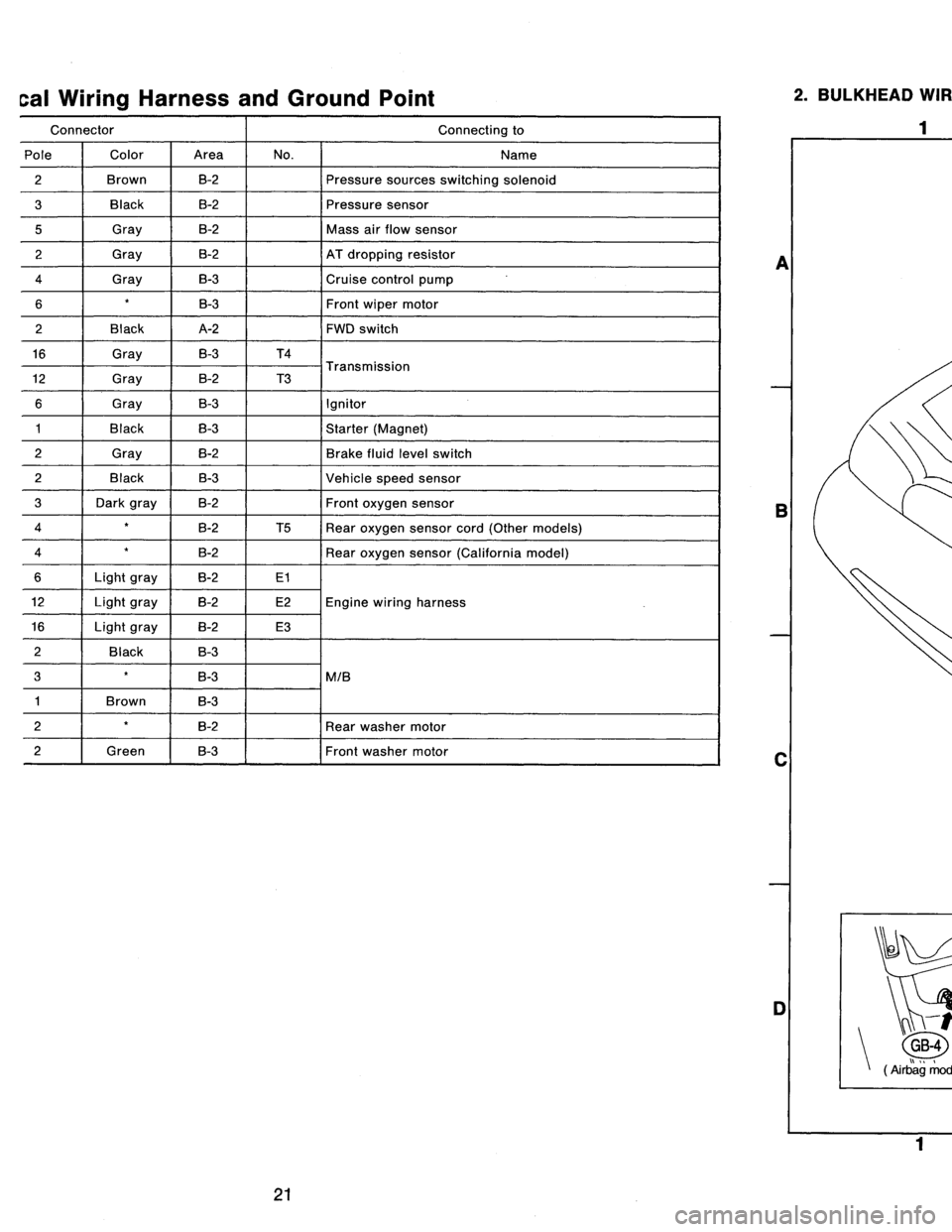
cal
Wiring
Harness
and
Ground
Point
Connector
Connecting
to
Pole
Color
Area
No
.
Name
2
Brown
B-2
Pressure
sources
switching
solenoid
3
Black
B-2
Pressure
sensor
5
Gray
B-2
Mass
air
flow
sensor
2
Gray
B-2
AT
dropping
resistor
4
Gray
B-3
Cruise
control
pump
6B-3Front
wipermotor
2
Black
A-2
FWD
switch
16
Gray
B-3
T4
T
i
12
Gray
B-2
T3
ransmiss
on
6
Gray
B-3
Ignitor
1
Black
B-3
Starter
(Magnet)
2
Gray
B-2
Brake
fluid
level
switch
2
Black
B-3
Vehicle
speed
sensor
3
Dark
gray
B-2
Front
oxygen
sensor
4
B-2
T5
Rear
oxygen
sensor
cord
(Other
models)
4
B-2
Rear
oxygen
sensor
(California
model)
6Light
gray
B-2
E1
12Light
gray
B-2
E2Engine
wiring
harness
16Light
gray
B-2
E3
2
Back
B-3
3
B-3
MIB
1
Brown
B-3
2B-2
Rear
washer
motor
2f
Green
B-3Front
washer
motor
2
.
BULKHEAD
WIRING
HARNESS
AND
GROUND
POINT
(IN
ENGINE
ROOM)
2
I
a
B
C
-r
t
n
GB-4
GB-5
(
rbag
mode
)
B6M0086B
D
1
3
4
4
[D802]
B6M0587A
A
B
C
D
21
Page 189 of 2890
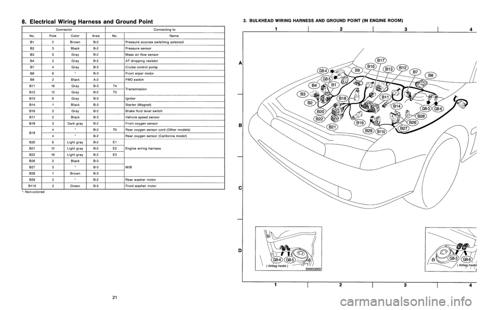
8
.
Electrical
Wiring
Harness
and
Ground
Point
Connector
Connecting
to
No
.
Pole
Color
Area
No
.
Name
131
2
Brown
B-2
Pressure
sources
switching
solenoid
B2
3
Black
B-2
Pressure
sensor
B3
5
Gray
B-2
Mass
air
slow
sensor
B4
2
Gray
B-2
AT
dropping
resistor
B7
4
Gray
B-3
Cruise
control
pump
B8
6B-3Front
wiper
motor
B9
2
Black
A-2
FWD
switch
B11
16
Gray
B-3
T4
T
B12
12
Gray
B-2
T3
ransmission
B13
6
Gray
B-3
Ignitor
B14
1
Black
B-3
Starter
(Magnet)
B16
2
Gray
B-2
Brake
fluid
level
switch
B17
2
Black
B-3
Vehicle
speed
sensor
B18
3
Dark
gray
B-2Front
oxygen
sensor
4B-2
T5Rear
oxygen
sensor
cord(Other
models)
B19
4B-2
Rear
oxygen
sensor
(California
model)
B20
6Light
gray
B-2El
821
12
Light
gray
B-2
E2Engine
wiring
harness
B22
16
Light
gray
B-2
E3
B26
2
Black
B-3
B27
3B-3
MIB
B28
1
Brown
B-3
B29
2B-2
Rear
washer
motor
B110
~
2
f
Green
B-3
~
Front
washer
motor
`
:
Non-colored
2
.
BULKHEAD
WIRING
HARNESS
AND
GROUND
POINT
(IN
ENGINE
ROOM)
1
2
3
a
E
C
DI
Yi-t
~
GB-4GB-5
(Air
`bag
model
(
Airbag
model
~rrE
1
23
4
21
Page 190 of 2890
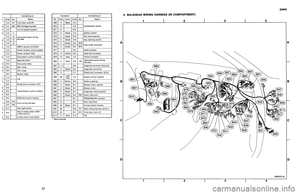
r
Connecting
to
)r
Area
No
.
Name
C-4
D1
Front
doorcord
RH
ow
C-4
ABi
SRS
(Airbag)
harness
;k
C-4
Turn
&
hazard
module
.k
C-3
i1
C-3
i2
instrument
panel
wiring
un
C-3
i3
harness
e
C-3
i4
y
C-3
OBD-IIservice
connector
C-3
Power
window
circuit
breaker
C-3
Power
window
relay
;k
C-3
Illuminationcontrol
module
C-3
Seat
belt
timer
;n
B-4
Fuel
pump
relay
vn
B-4
Main
relay
;k
B-4
Horn
relay
B-4
Blower
relay
y
C-4
FIB
y
C-4
B-3
Shield
joint
connector
(AT)
.k
B-3
:k
B-3
Transmission
control
module
.k
B-3
:k
B-3
Shift-lock
control
module
B-4F44
i
h
B-4F45
Front
w
ring
arness
.k
B-3
Stop
light
switch
,k
B-3
Stop
8
brake
switch
(Withcruise
control)
:k
8-3
Cruise
control
sub
switch
Connector
Connecting
to
No
.
Pole
Color
Area
No
.
Name
869
11
Black
C-3
B70
9
C-3
Combination
switch
B71
8
8-3
B72
6
Black
C-3
Ignition
switch
B73
2
Black
B-3
Key
lock
solenoid
B74
2
Black
B-3
Key
warning
switch
B75
2
Green
B-2
876
T
d
B76
2
Green
8-2
875
e
connector
est
mo
877
7
B-2
Mode
actuator
B78
9
Yellow
B-2
Data
link
connector
B79
14
Gray
C-2
Check
connector
BBO
4
Blue
B-2
i20
Instrument
panel
wiring
harness
B81
1
x
2
B-2
Diagnosis
terminal
(Ground)
B82
6
Black
B-2
Diagnosisconnector
BB3
4
C-1
Shield
joint
connector
(EIG)
BBQ
96Lightblue
C-2
Engine
control
module
B85
4
Brown
B-3
Diode
(Lighting)
B86
4
Black
B-1
Blower
motor
resistor
887
2
Black
B-1
Blower
motor
888
3
Black
B-1
Evaporatorthermoswitch
B90
2
Green
B-4
R50
Room
light
cord
B91
5
B-1
FRESHIRECIRC
actuator
B92
8
B-1
Door
lock
timer
894
20
Black
B-1
Cruise
control
module
B97
56
B-4
R1
Rear
wiring
harness
(S.M
.J
.)
B101
24
B-1
D11
Front
door
cord
LH
8111
3
Gray
C-4FIB
`
:
Non-colored
4
.
BULKHEAD
WIRING
HARNESS
(IN
COMPARTMENT)
1
I
2
I
3
I
4
A
B
C
D
1
I
2
I
3
I
4
[oeo41
B6M0513A
A
B
C
iJ
23
Page 191 of 2890
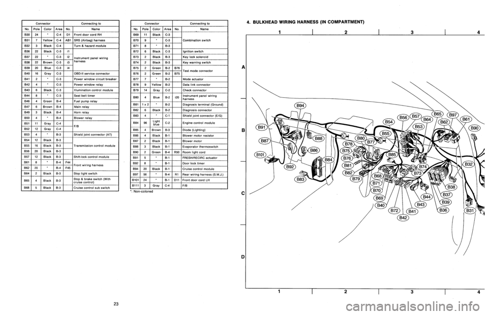
Connector
Connecting
to
No
.
Pole
Color
Area
No
.
Name
830
24
C-4
D1
Front
door
cord
RH
831
7
Yellow
C-4
A81
SRS
(Airbag)
harness
B32
3
Black
C-4
Turn
&
hazard
module
B36
22
Black
C-3
i1
B37
22
C-3
i2
Instrument
panel
wiring
B38
22
Brown
C-3
i3
harness
B39
20Blue
C-3
i4
B40
16
Gray
C-3
OBD-II
service
connector
B41
2
C-3
Power
window
circuit
breaker
842
4
C-3
Power
window
relay
B43
6
Black
C-3
Illumination
control
module
B44
8
C-3
Seat
belt
timer
B46
4
Green
B-4
Fuel
pump
relay
B47
6
Brown
B-4
Main
relay
B49
3
Black
B-4
Horn
relay
850
4
B-4
Blower
relay
851
11
Gray
C-4
FIB
B52
12
Gray
C-4
853
4
B-3
Shield
joint
connector
(AT)
B54
12
Black
B-3
B55
16
Black
B-3
Transmission
control
module
B56
20
Black
B-3
B57
12
Black
B-3
Shift-lock
control
module
861
B
B-4
F44
B62
20
B-4
F45
Front
wiring
harness
B64
2
Black
B-3
Stop
light
switch
B65
4
Black
B-3
Stop
&
brake
switch(Withcruise
control)
B68
5
i
Black
i
B-3
Cruise
control
sub
switch
Connector
Connecting
to
No
.
Pole
Color
Area
No
.
Name
B69
11
Black
C-3
B70
9
C-3
Combination
switch
B71
8
8-3
B72
6
Black
C-3
Ignition
switch
B73
2
Black
B-3
Key
lock
solenoid
B74
2
Black
B-3
Key
warning
switch
B75
2
Green
B-2
B76
B76
2
Green
&2
B75
Test
mode
connector
B77
7
B-2
Made
actuator
B78
9
Yellow
B-2
Data
link
connector
B79
14
Gray
C-2
Check
connector
B80
4
Blue
B-2
i20
Instrumentpanel
wiring
harness
B81
1
x
2
B-2
Diagnosis
terminal
(Ground)
B82
6
Black
B-2
Diagnosis
connector
B83
4
C-1
Shield
joint
connector
(E!G)
884
96
Light
blue
C-2
Engine
control
module
885
4
Brown
B-3
Diode
(Lighting)
B86
4
Black
B-1
Blower
motor
resistor
887
2
Black
B-1
Blower
motor
B88
3
Black
8-t
Evaporator
thermoswitch
890
2
Green
B-4
R50
Room
light
cord
B91
5B-1
FRESHIRECIRC
actuator
892
8
B-1
Door
lock
timer
B94
20
Black
B-1
Cruise
control
module
B97
56
B-4
R1Rear
wiring
harness
(S
.M
.J
.)
B101
24
B-1
D11
Front
doorcord
LH
13111
3
Gray
C-4
FIB
`
:
Non-colored
4
.
BULKHEAD
WIRING
HARNESS
(IN
COMPARTMENT)
A
B
C
1]
4
23
Page 192 of 2890
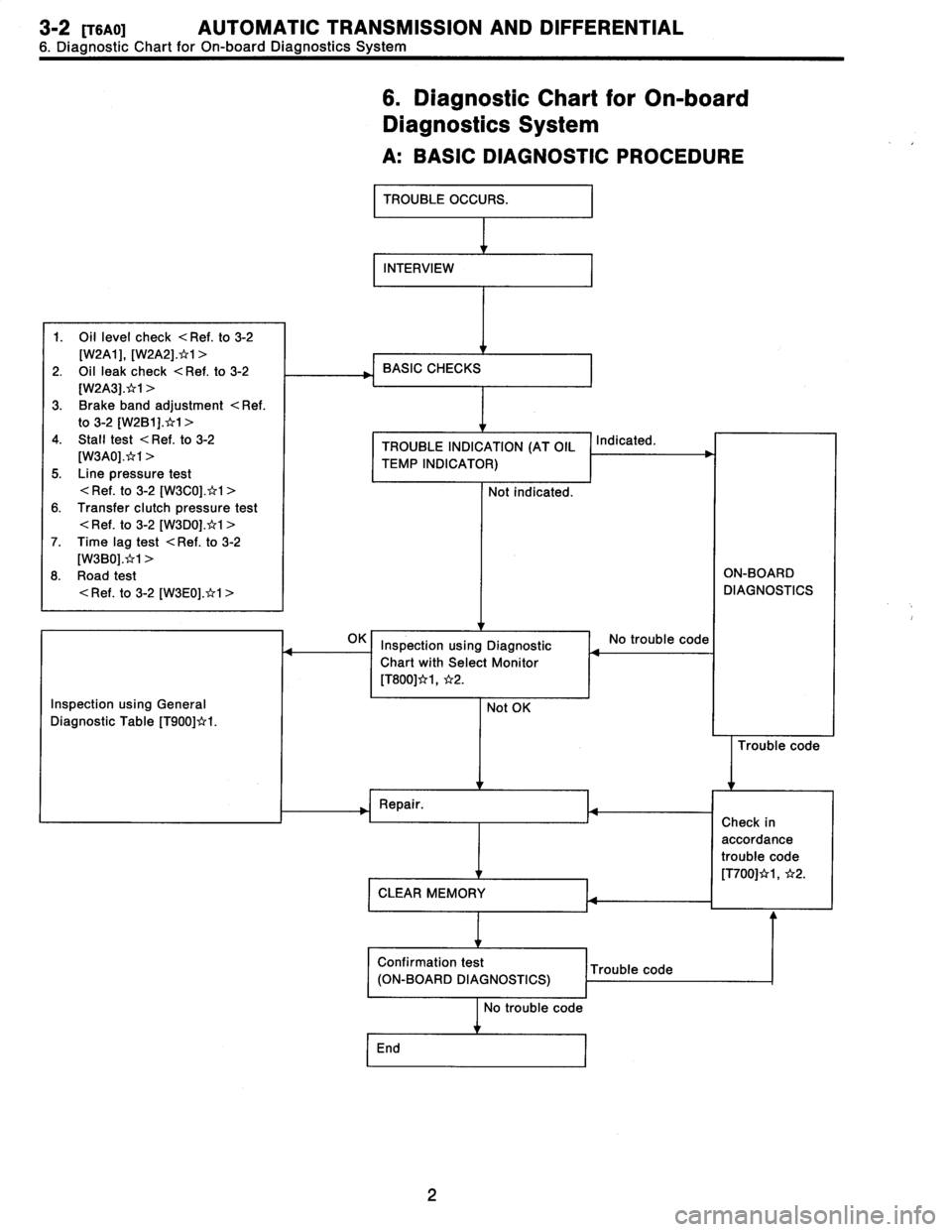
3-2
[TSAO1
AUTOMATIC
TRANSMISSION
AND
DIFFERENTIAL
6
.
Diagnostic
Chart
for
On-board
Diagnostics
System
6
.
Diagnostic
Chart
for
On-board
Diagnostics
System
A
:
BASICDIAGNOSTIC
PROCEDURE
TROUBLE
OCCURS
.
INTERVIEW
1
.
Oil
level
check
<
Ref
.
to
3-2
[W2A1],
[W2A2]
.*1
>
2
.
Oil
leak
check
<
Ref
.
to
3-2
[W2A3]
.x`r1
>
3
.
Brake
band
adjustment
<
Ref
.
to
3-2
[W2B1]
.t`r1
>
4
.
Stall
test
<
Ref
.
to
3-2
[W3A0]
.*1
>
5
.
Line
pressure
test
<
Ref
.
to
3-2
[W3C0]
.*1
>
6
.
Transfer
clutch
pressure
test
<
Ref
.
to
3-2
[W3D0]
.*1
>
7
.
Time
lag
test
<
Ref
.
to
3-2
[W3B0]
.*1
>
8
.
Road
test
<
Ref
.
to
3-2
[W3E0]
.*1
>
BASIC
CHECKS
TROUBLE
INDICATION
(AT
OIL
TEMP
INDICATOR)
Not
indicated
.
Indicated
.
ON-BOARD
DIAGNOSTICS
Inspection
using
General
Diagnostic
Table
[T900]*I
.
I
Inspection
using
Diagnostic
Chart
with
Select
Monitor
[T800]*1,
*2
.
Not
OK
No
trouble
code
Trouble
code
Repair
.
CLEAR
MEMORY
Confirmation
test
Trouble
code
(ON-BOARD
DIAGNOSTICS)
No
trouble
code
End
Check
in
accordance
trouble
code
[T700]*1,
*2
.
2