Page 907 of 2890
G3M0332
6) Install the oil charge pipe.
Tightening torque:
Upper
41±3 N⋅m (4.2±0.3 kg-m, 30.4±2.2 ft-lb)
Lower
6.4±0.5 N⋅m (0.65±0.05 kg-m, 4.7±0.4 ft-lb)
CAUTION:
Be careful not to damage the O-ring.
G3M0348
7) Adjustment of brake band
(1) After tightening the brake band adjusting screw
with ST to 9 N⋅m (0.9 kg-m, 6.5 ft-lb) torque, back it off
three turns. Then secure with a lock nut.
ST 398603610 SOCKET WRENCH
Tightening torque:
26±2 N⋅m (2.7±0.2 kg-m, 19.5±1.4 ft-lb)
NOTE:
When tightening the lock nut, be careful not to turn the
adjusting screw.
B3M0114A
8) Install the air breather hose.
�
1Air breather hose (Transmission case)
�
2Air breather hose (Oil pump housing)
B3M0113
9) Install the pitching stopper bracket.
Tightening torque:
41±3 N⋅m (4.2±0.3 kg-m, 30.4±2.2 ft-lb)
81
3-2SERVICE PROCEDURE
4. Overall Transmission
Page 960 of 2890

B3M0417A
8) Insert the thread portion of the other inner cable end
into the connector hole of the selector lever, and fix the
other outer cable end to the bracket.
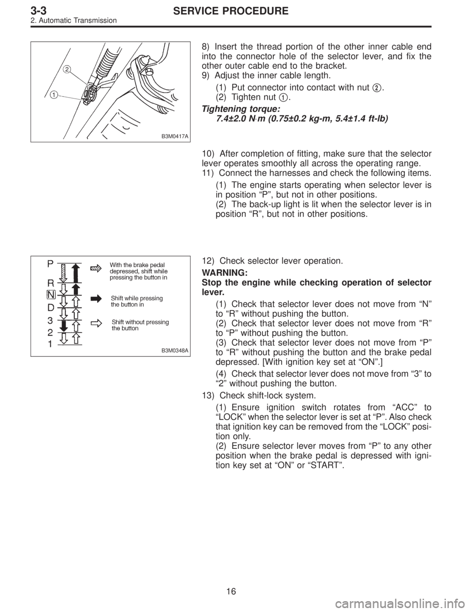
9) Adjust the inner cable length.
(1) Put connector into contact with nut�
2.
(2) Tighten nut�
1.
Tightening torque:
7.4±2.0 N⋅m (0.75±0.2 kg-m, 5.4±1.4 ft-lb)
10) After completion of fitting, make sure that the selector
lever operates smoothly all across the operating range.
11) Connect the harnesses and check the following items.
(1) The engine starts operating when selector lever is
in position“P”, but not in other positions.
(2) The back-up light is lit when the selector lever is in
position“R”, but not in other positions.
B3M0348A
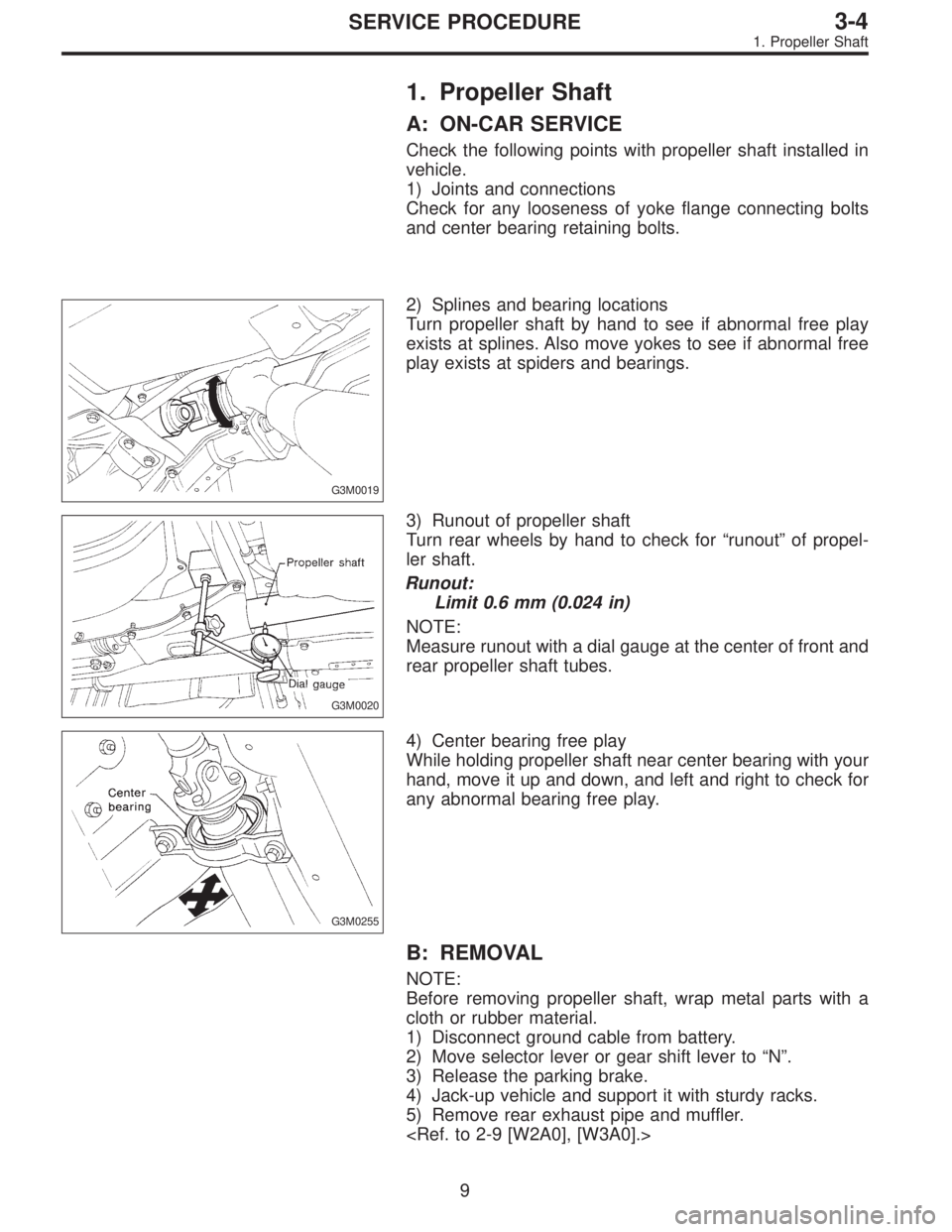
12) Check selector lever operation.
WARNING:
Stop the engine while checking operation of selector
lever.
(1) Check that selector lever does not move from“N”
to“R”without pushing the button.
(2) Check that selector lever does not move from“R”
to“P”without pushing the button.
(3) Check that selector lever does not move from“P”
to“R”without pushing the button and the brake pedal
depressed. [With ignition key set at“ON”.]
(4) Check that selector lever does not move from“3”to
“2”without pushing the button.
13) Check shift-lock system.
(1) Ensure ignition switch rotates from“ACC”to
“LOCK”when the selector lever is set at“P”. Also check
that ignition key can be removed from the“LOCK”posi-
tion only.
(2) Ensure selector lever moves from“P”to any other
position when the brake pedal is depressed with igni-
tion key set at“ON”or“START”.
16
3-3SERVICE PROCEDURE
2. Automatic Transmission
Page 968 of 2890

1. Propeller Shaft
A: ON-CAR SERVICE
Check the following points with propeller shaft installed in
vehicle.
1) Joints and connections
Check for any looseness of yoke flange connecting bolts
and center bearing retaining bolts.
G3M0019
2) Splines and bearing locations
Turn propeller shaft by hand to see if abnormal free play
exists at splines. Also move yokes to see if abnormal free
play exists at spiders and bearings.
G3M0020
3) Runout of propeller shaft
Turn rear wheels by hand to check for“runout”of propel-
ler shaft.
Runout:
Limit 0.6 mm (0.024 in)
NOTE:
Measure runout with a dial gauge at the center of front and
rear propeller shaft tubes.
G3M0255
4) Center bearing free play
While holding propeller shaft near center bearing with your
hand, move it up and down, and left and right to check for
any abnormal bearing free play.
B: REMOVAL
NOTE:
Before removing propeller shaft, wrap metal parts with a
cloth or rubber material.
1) Disconnect ground cable from battery.
2) Move selector lever or gear shift lever to“N”.
3) Release the parking brake.
4) Jack-up vehicle and support it with sturdy racks.
5) Remove rear exhaust pipe and muffler.
9
3-4SERVICE PROCEDURE
1. Propeller Shaft
Page 973 of 2890
2. Rear Differential
A: ON-CAR SERVICE
1. FRONT OIL SEAL
1) Disconnect ground cable from battery.
2) Move selector lever or gear shift lever to“N”.
3) Release the parking brake.
B3M0316A
4) Remove oil drain plug, and drain gear oil.
G3M0024
5) Jack-up rear wheels and support the vehicle body with
sturdy racks.
6) Remove propeller shaft from body.
[W1B0].>
CAUTION:
Wrap metal parts with a cloth or rubber material to
prevent damage from adjacent metal parts.
G3M0034
7) Remove self-locking nut while holding companion
flange with ST.
ST 498427200 FLANGE WRENCH
G3M0035
8) Extract companion flange with a puller.
14
3-4SERVICE PROCEDURE
2. Rear Differential
Page 975 of 2890
2. SIDE OIL SEAL
1) Disconnect ground cable from battery.
2) Move selector lever or gear shift lever to“N”.
3) Release the parking brake.
4) Loosen both wheel nuts.
5) Jack-up the vehicle and support it with rigid racks.
6) Remove wheels.
7) Remove rear exhaust pipe and muffler.
G3M0038
8) Remove the DOJ of rear drive shaft from rear differen-
tial.
(1) Remove the A.B.S. sensor cable clamp and park-
ing brake cable clamp from bracket.
G3M0039
(2) Remove the A.B.S. sensor cable clamp from the
trailing link.
G3M0040
(3) Remove the A.B.S. sensor cable clamp and park-
ing brake cable guide from the trailing link.
G3M0041
(4) Remove the rear stabilizer link.
16
3-4SERVICE PROCEDURE
2. Rear Differential
Page 978 of 2890
B: REMOVAL
1) Disconnect ground cable from battery.
2) Move selector lever or gear shift lever to“N”.
3) Release the parking brake.
4) Loosen wheel nuts.
5) Jack-up vehicle and support it with sturdy racks.
6) Remove wheels.
7) Remove rear exhaust pipe and muffler.
G3M0021
8) Remove front exhaust cover.
G3M0022
9) Remove front cover of rear differential mount.
G3M0024
10) Remove propeller shaft.
CAUTION:
When removing propeller shaft, pay attention not to
damage the sliding surfaces of rear drive shaft (exten-
sion) spline, oil seal and sleeve yoke.
NOTE:
Prepare an oil can and cap since the transmission oil flows
out from the extension at removing propeller shaft.
G3M0026
NOTE:
Insert the cap into the extension to prevent transmission oil
from flowing out immediately after removing the propeller
shaft.
19
3-4SERVICE PROCEDURE
2. Rear Differential
Page 979 of 2890
G3M0053
11) Remove heat sealed cover.
12) Remove clamps and bracket of parking brake cable.
13) Remove crossmember reinforcement lower (AWD
Sedan only).
G3M1020
14) Remove DOJ of rear drive shaft from rear differential
using ST.
ST 28099PA100 DRIVE SHAFT REMOVER
G3M1022
15) Secure rear drive shaft to rear crossmember using
wire.
G3M0054
16) Remove lower differential bracket.
G3M0055
17) Support rear differential with transmission jack.
20
3-4SERVICE PROCEDURE
2. Rear Differential
Page 996 of 2890

G3M1050
19) Install rear cover and tighten bolts to specified torque.
Tightening torque:
29±5 N⋅m (3.0±0.5 kg-m, 21.7±3.6 ft-lb)
F: INSTALLATION
To install, reverse the removal sequence.
1) Install the air breather cap tapping with a plastic ham-
mer.
CAUTION:
Be sure to install new air breather cap.
2) Position front member on body by passing it under park-
ing brake cable and securing to rear differential.
NOTE:
When installing rear differential front member, do not con-
fuse the installation sequence of the upper and lower stop-
pers.
G3M1026
3) Install DOJ of rear drive shaft into rear differential.
to 3-4 [W2A2].>
ST 28099PA090 SIDE OIL SEAL PROTECTOR
G3M1051
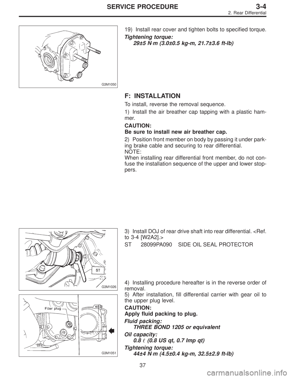
4) Installing procedure hereafter is in the reverse order of
removal.
5) After installation, fill differential carrier with gear oil to
the upper plug level.
CAUTION:
Apply fluid packing to plug.
Fluid packing:
THREE BOND 1205 or equivalent
Oil capacity:
0.8�(0.8 US qt, 0.7 Imp qt)
Tightening torque:
44±4 N⋅m (4.5±0.4 kg-m, 32.5±2.9 ft-lb)
37
3-4SERVICE PROCEDURE
2. Rear Differential