Page 997 of 2890
3. Rear Differential Front Member
A: REMOVAL
1) Disconnect ground cable from battery.
2) Move selector lever or gear shift lever to“N”.
3) Release the parking brake.
4) Loosen wheel nuts.
5) Jack-up vehicle and support it with sturdy racks.
6) Remove wheels.
7) Remove rear exhaust pipe and muffler.
8) Remove rear differential front member.
NOTE:
When removing rear differential front member, work the
removal procedure as rear differential.
38
3-4SERVICE PROCEDURE
3. Rear Differential Front Member
Page 998 of 2890
G3M1029
B: INSTALLATION
To install, reverse the removal sequence.
1) Position front member on body by passing it under park-
ing brake cable and securing to rear differential.
G3M0101
NOTE:
When installing rear differential front member, do not con-
fuse the installation sequence of the stopper.
G3M1026
2) Insert DOJ of rear drive shaft into rear differential.
ST 28099PA090 SIDE OIL SEAL PROTECTOR
CAUTION:
Before inserting, replace the differential side oil seal
and the circlip at the end of the spline shaft with a new
one.
3) Installing procedure hereafter is in the reverse order of
removal.
39
3-4SERVICE PROCEDURE
3. Rear Differential Front Member
Page 1016 of 2890
7. STEERING ANGLE
�Inspection
1) Place vehicle on a turning radius gauge.
2) While depressing brake pedal, turn steering wheel fully
to the left and right. With steering wheel held at each fully
turned position, measure both the inner and outer wheel
steering angle.
Steering angle:
Inner wheel 37.6°±1.5°
Outer wheel 32.6°±1.5°
G4M0482
�Adjustment
Turn tie-rod to adjust steering angle of both inner and outer
wheels.
CAUTION:
�Check toe-in.
�Correct boot if it is twisted.
15
4-1SERVICE PROCEDURE
1. On-car Services
Page 1022 of 2890
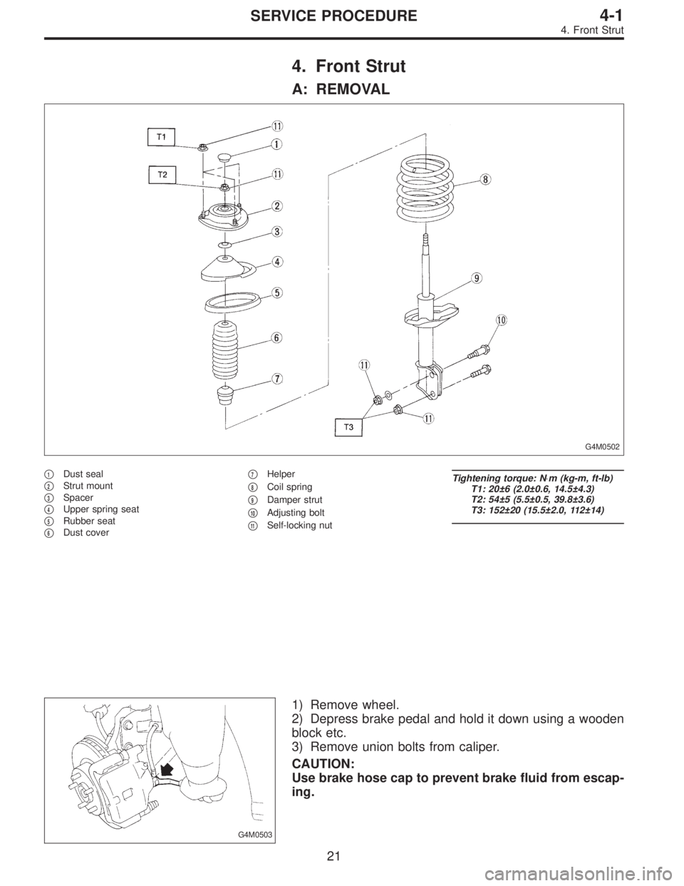
4. Front Strut
A: REMOVAL
G4M0502
�1Dust seal
�
2Strut mount
�
3Spacer
�
4Upper spring seat
�
5Rubber seat
�
6Dust cover�
7Helper
�
8Coil spring
�
9Damper strut
�
10Adjusting bolt
�
11Self-locking nut
Tightening torque: N⋅m (kg-m, ft-lb)
T1: 20±6 (2.0±0.6, 14.5±4.3)
T2: 54±5 (5.5±0.5, 39.8±3.6)
T3: 152±20 (15.5±2.0, 112±14)
G4M0503
1) Remove wheel.
2) Depress brake pedal and hold it down using a wooden
block etc.
3) Remove union bolts from caliper.
CAUTION:
Use brake hose cap to prevent brake fluid from escap-
ing.
21
4-1SERVICE PROCEDURE
4. Front Strut
Page 1023 of 2890
G4M0504
4) Remove brake hose clamp and disconnect brake hose
from strut. Attach brake hose to body using gum tape.
5) Scribe an alignment mark on the camber adjusting bolt
which secures strut to housing.
6) Remove bolt securing the A.B.S. sensor harness.
(A.B.S. equipped models.)
G4M0505
7) Remove two bolts securing housing to strut.
CAUTION:
While holding head of adjusting bolt, loosen self-lock-
ing nut.
8) Remove the three nuts securing strut mount to body.
G4M0506
B: DISASSEMBLY
1) Using a coil spring compressor, compress coil spring.
G4M0507
2) Using ST, remove self-locking nut.
ST 927760000 STRUT MOUNT SOCKET
3) Remove strut mount, upper spring seat and rubber seat
from strut.
4) Gradually decreasing compression force of spring
compressor, and remove coil spring.
5) Remove dust cover and helper.
22
4-1SERVICE PROCEDURE
4. Front Strut
Page 1026 of 2890
 Pull the piston rod fully upward, and install rubber seat
and spring seat.
NOTE:
Ensure that upper spring seat is positioned with“OUT”
mark facing outward.
8) Install strut mount to the")
G4M0511
7) Pull the piston rod fully upward, and install rubber seat
and spring seat.
NOTE:
Ensure that upper spring seat is positioned with“OUT”
mark facing outward.
8) Install strut mount to the piston rod, and tighten the
self-locking nut temporarily.
CAUTION:
Be sure to use a new self-locking nut.
G4M0507
9) Using hexagon wrench to prevent strut rod from turning,
tighten self-locking nut with ST.
Tightening torque:
54±5 N⋅m (5.5±0.5 kg-m, 39.8±3.6 ft-lb)
ST 927760000 STRUT MOUNT SOCKET
10) Loosen the coil spring carefully.
E: INSTALLATION
1) Install strut mount at upper side of strut to body and
tighten with nuts.
Tightening torque:
20±6 N⋅m (2.0±0.6 kg-m, 14.5±4.3 ft-lb)
2) Connect housing to lower side of strut.
3) Position aligning mark on camber adjusting bolt with
aligning mark on lower side bracket of strut.
CAUTION:
�While holding head of adjusting bolt, tighten self-
locking nut.
�Be sure to use new self-locking nut.
Tightening torque:
152±20 N⋅m (15.5±2.0 kg-m, 112±14 ft-lb)
4) Install A.B.S. sensor harness to strut. (A.B.S. equipped
models.)
Tightening torque:
152±20 N⋅m (15.5±2.0 kg-m, 112±14 ft-lb)
5) Install brake hose at lower side of strut with clamp.
G4M0503
6) Install union bolts which secure brake caliper to brake
hose.
Tightening torque:
18±3 N⋅m (1.8±0.3 kg-m, 13.0±2.2 ft-lb)
CAUTION:
Be sure to bleed air from brake system.
7) Install wheels.
NOTE:
Check wheel alignment and adjust if necessary.
25
4-1SERVICE PROCEDURE
4. Front Strut
Page 1030 of 2890
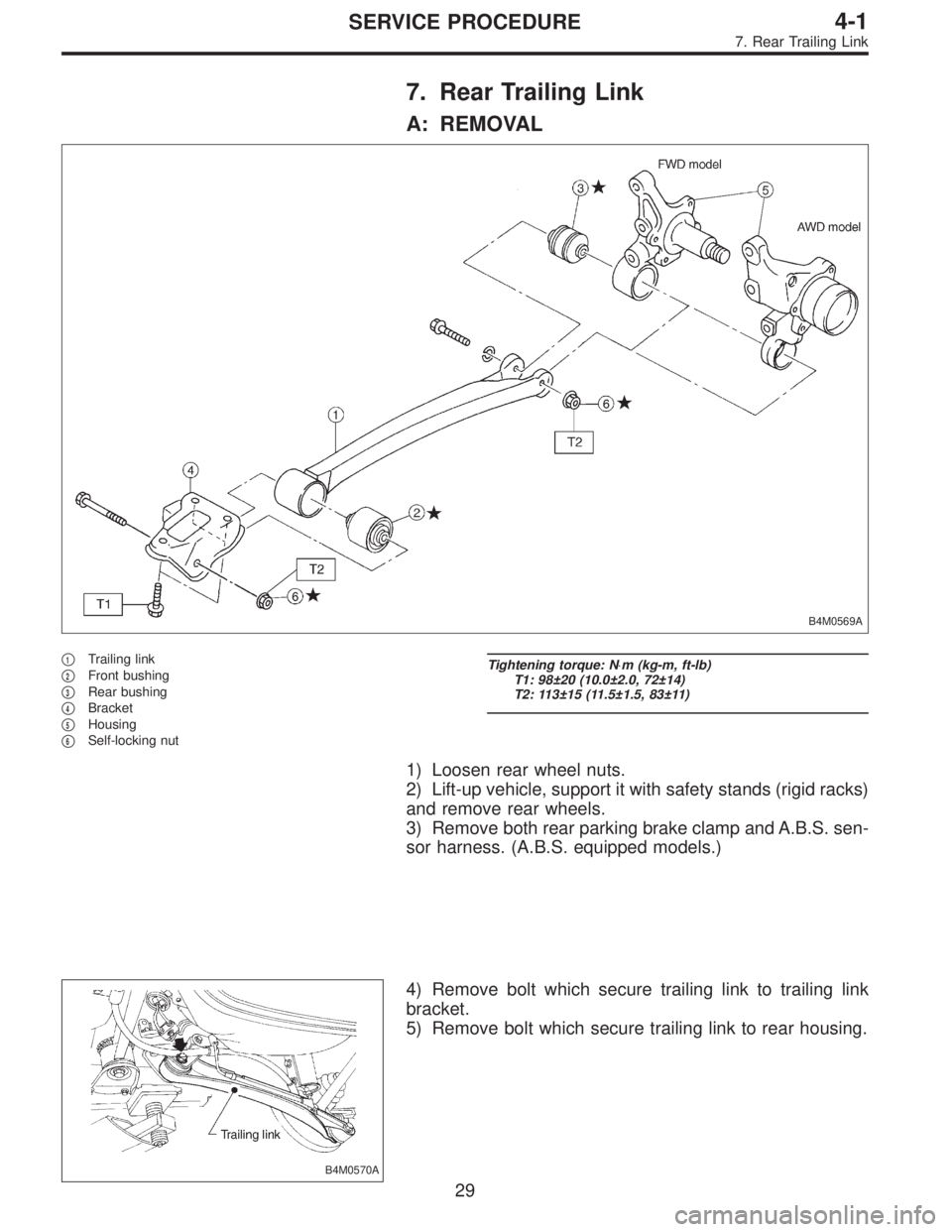
7. Rear Trailing Link
A: REMOVAL
B4M0569A
�1Trailing link
�
2Front bushing
�
3Rear bushing
�
4Bracket
�
5Housing
�
6Self-locking nut
Tightening torque: N⋅m (kg-m, ft-lb)
T1: 98±20 (10.0±2.0, 72±14)
T2: 113±15 (11.5±1.5, 83±11)
1) Loosen rear wheel nuts.
2) Lift-up vehicle, support it with safety stands (rigid racks)
and remove rear wheels.
3) Remove both rear parking brake clamp and A.B.S. sen-
sor harness. (A.B.S. equipped models.)
B4M0570A
4) Remove bolt which secure trailing link to trailing link
bracket.
5) Remove bolt which secure trailing link to rear housing.
29
4-1SERVICE PROCEDURE
7. Rear Trailing Link
Page 1041 of 2890
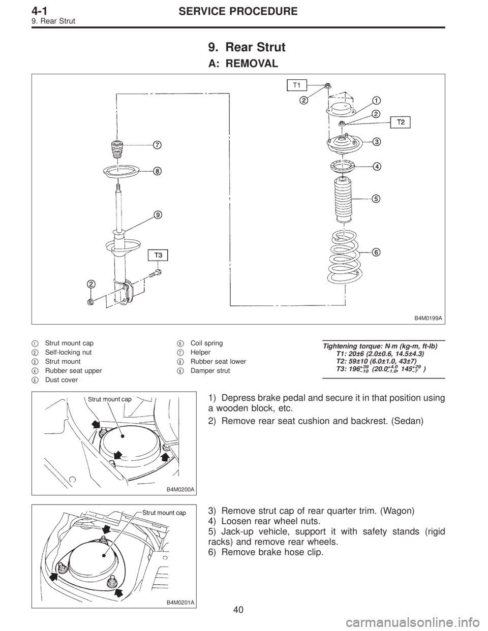
9. Rear Strut
A: REMOVAL
B4M0199A
�1Strut mount cap
�
2Self-locking nut
�
3Strut mount
�
4Rubber seat upper
�
5Dust cover�
6Coil spring
�
7Helper
�
8Rubber seat lower
�
9Damper strut
Tightening torque: N⋅m (kg-m, ft-lb)
T1: 20±6 (2.0±0.6, 14.5±4.3)
T2: 59±10 (6.0±1.0, 43±7)
T3: 196
+39
�10(20.0+4.0
�1.0, 145+29
�7)
B4M0200A
1) Depress brake pedal and secure it in that position using
a wooden block, etc.
2) Remove rear seat cushion and backrest. (Sedan)
B4M0201A
3) Remove strut cap of rear quarter trim. (Wagon)
4) Loosen rear wheel nuts.
5) Jack-up vehicle, support it with safety stands (rigid
racks) and remove rear wheels.
6) Remove brake hose clip.
40
4-1SERVICE PROCEDURE
9. Rear Strut
 Disconnect ground cable from battery.
2) Move selector lever or gear shift lever to“N”.
3) Release the parking brake.
4) Loosen wheel nuts.
5) Jack-")
 Position front member on body by passing it under park-
ing brake cable and securing to rear differential.
G3M0101
NOTE:
When insta")
 Remove brake hose clamp and disconnect brake hose
from strut. Attach brake hose to body using gum tape.
5) Scribe an alignment mark on the camber adjusting bolt
which secures strut to housi")