Page 424 of 2890
G2M0757
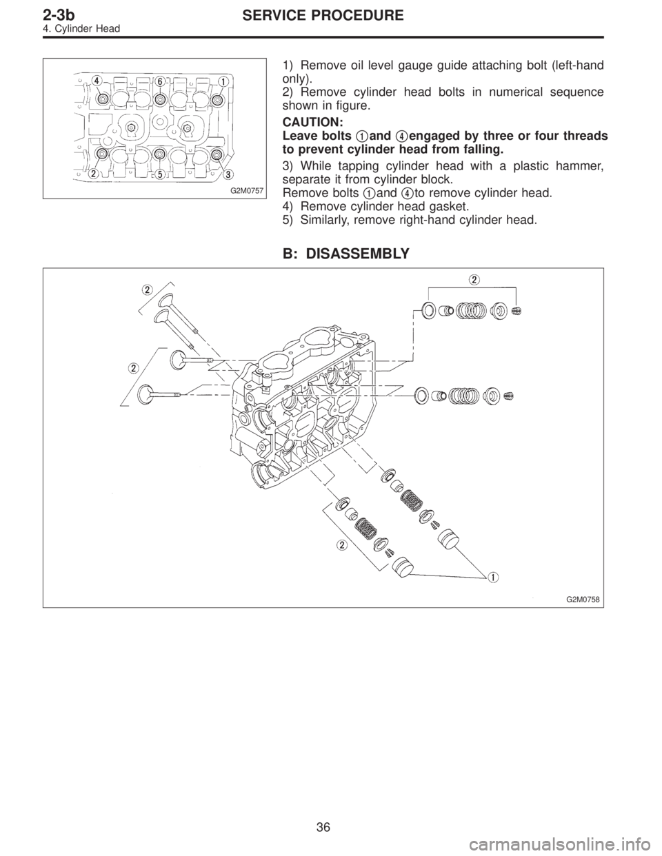
1) Remove oil level gauge guide attaching bolt (left-hand
only).
2) Remove cylinder head bolts in numerical sequence
shown in figure.
CAUTION:
Leave bolts�
1and�4engaged by three or four threads
to prevent cylinder head from falling.
3) While tapping cylinder head with a plastic hammer,
separate it from cylinder block.
Remove bolts�
1and�4to remove cylinder head.
4) Remove cylinder head gasket.
5) Similarly, remove right-hand cylinder head.
B: DISASSEMBLY
G2M0758
36
2-3bSERVICE PROCEDURE
4. Cylinder Head
Page 432 of 2890
(7) Further tighten all bolts by 80 to 90°in numerical
sequence.
CAUTION:
Ensure that the total“re-tightening angle”[steps (6)
and (7) above] do not exceed 180°.
3) Install oil level gauge guide attaching bolt (left side
only).
2. INTAKE MANIFOLD
1) Install camshafts, rocker cover and related parts.
G2M0750
Tightening torque: N⋅m (kg-m, ft-lb)
T1: 10±0.7 (1.0±0.07, 7.2±0.5)
T2: 20±2 (2.0±0.2, 14.5±1.4)
44
2-3bSERVICE PROCEDURE
4. Cylinder Head
Page 466 of 2890

2. Engine Noise
Valve lash adjusters may make clicking noise once engine
starts. It is normal if clicking noise ceases after a few min-
utes.
If clicking noise continues for more than a few minutes,
inspect Hydraulic Lash Adjuster (HLA) in accordance with
the following flow chart.
Inspect the engine oil level
(1) Adjust the oil level between“F”and“L”.
(2) Replace the oil when deteriorated.
Load less engine operation to bleed air from
HLA.
(1) Warm-up engine for about five minutes.
(2) If the noise is remaining, keep the engine
running at 2,000 rpm for up to 20 minutes until
the noise fades away.�Noise is eliminated.
Keep the engine running at 2,500 rpm for about
five minutes to bleed air completely.
Noise remains or comes
back.END
HLA is rigid and has no valve clearance.
Remove the rocker cover and inspect HLA.
Press HLA while it is facing the base circle of
the cam.
�HLA is normal. The noise may come from other
sources.
HLA is not rigid.
There is valve clearance.
Check whether the clearance between HLA and
the bushing of the cylinder head is within
allowance or not.
HLA is seized. Replace HLA.
�Out of allowance
Replace the cylinder head related parts or the
HLA, whichever is necessary.
Within allowance
Replace HLA.
�
�
�
�
�
�
78
2-3bDIAGNOSTICS
2. Engine Noise
Page 470 of 2890
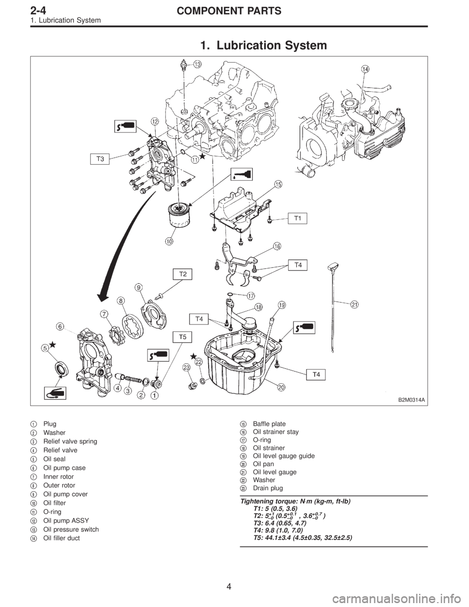
1. Lubrication System
B2M0314A
�1Plug
�
2Washer
�
3Relief valve spring
�
4Relief valve
�
5Oil seal
�
6Oil pump case
�
7Inner rotor
�
8Outer rotor
�
9Oil pump cover
�
10Oil filter
�
11O-ring
�
12Oil pump ASSY
�
13Oil pressure switch
�
14Oil filler duct�
15Baffle plate
�
16Oil strainer stay
�
17O-ring
�
18Oil strainer
�
19Oil level gauge guide
�
20Oil pan
�
21Oil level gauge
�
22Washer
�
23Drain plug
Tightening torque: N⋅m (kg-m, ft-lb)
T1: 5 (0.5, 3.6)
T2: 5
+1
�0(0.5+0.1
�0, 3.6+0.7
�0)
T3: 6.4 (0.65, 4.7)
T4: 9.8 (1.0, 7.0)
T5: 44.1±3.4 (4.5±0.35, 32.5±2.5)
4
2-4COMPONENT PARTS
1. Lubrication System
Page 480 of 2890
B2M0724
13) Connect connector to front oxygen sensor.
B2M0725
14) Connect connector to rear oxygen sensor. (California
2200 cc model only)
G2M0302
15) Install pitching stopper.
Tightening torque:
T1: 49±5 N⋅m (5.0±0.5 kg-m, 36.2±3.6 ft-lb)
T2: 57±10 N⋅m (5.8±1.0 kg-m, 42±7 ft-lb)
B2M0320
16) Install radiator upper brackets.
Tightening torque:
12±3 N⋅m (1.2±0.3 kg-m, 8.7±2.2 ft-lb)
B2M0321
17) Install air intake duct.
18) Fill engine oil through filler pipe up to upper point of
level gauge.
Engine oil capacity:
2200 cc ; Upper level
4.0�(4.2 US qt, 3.5 Imp qt)
Lower level
3.0�(3.2 US qt, 2.6 Imp qt)
2500 cc ; Upper level
4.5�(4.8 US qt, 4.0 Imp qt)
14
2-4SERVICE PROCEDURE
2. Oil Pan and Oil Strainer
Page 481 of 2890
Lower level
3.5�(3.7 US qt, 3.1 Imp qt)
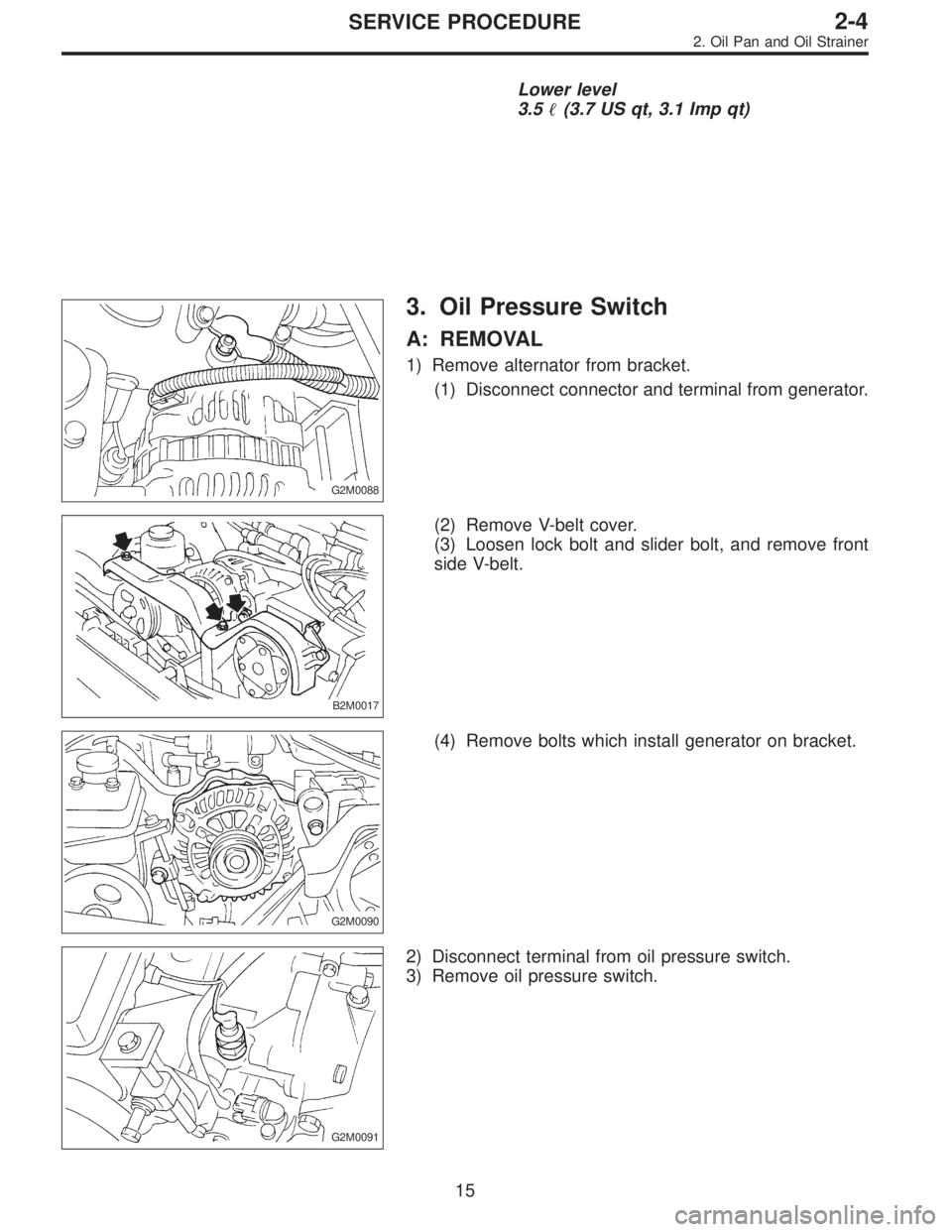
G2M0088
3. Oil Pressure Switch
A: REMOVAL
1) Remove alternator from bracket.
(1) Disconnect connector and terminal from generator.
B2M0017
(2) Remove V-belt cover.
(3) Loosen lock bolt and slider bolt, and remove front
side V-belt.
G2M0090
(4) Remove bolts which install generator on bracket.
G2M0091
2) Disconnect terminal from oil pressure switch.
3) Remove oil pressure switch.
15
2-4SERVICE PROCEDURE
2. Oil Pan and Oil Strainer
Page 482 of 2890
Lower level
3.5�(3.7 US qt, 3.1 Imp qt)
G2M0088
3. Oil Pressure Switch
A: REMOVAL
1) Remove alternator from bracket.
(1) Disconnect connector and terminal from generator.
B2M0017
(2) Remove V-belt cover.
(3) Loosen lock bolt and slider bolt, and remove front
side V-belt.
G2M0090
(4) Remove bolts which install generator on bracket.
G2M0091
2) Disconnect terminal from oil pressure switch.
3) Remove oil pressure switch.
15
2-4SERVICE PROCEDURE
2. Oil Pan and Oil Strainer
Page 484 of 2890
 O")
1. Engine Lubrication System
Before troubleshooting, make sure that the engine oil level
is correct and no oil leakage exists.
Trouble Possible cause Corrective action
1. Warning light remains
on.1) Oil pressure switch
failureCracked diaphragm or oil leakage within switch Replace.
Broken spring or seized contacts Replace.
2) Low oil pressureClogged oil filter Replace.
Malfunction of oil by-pass valve of oil filter Clean or replace.
Malfunction of oil relief valve of oil pump Clean or replace.
Clogged oil passage Clean.
Excessive tip clearance and side clearance of oil
pump rotor and gearReplace.
Clogged oil strainer or broken pipe Clean or replace.
3) No oil pressureInsufficient engine oil Replenish.
Broken pipe of oil strainer Replace.
Stuck oil pump rotor Replace.
2. Warning light does not
go on.1) Burn-out bulb Replace.
2) Poor contact of switch contact points Replace.
3) Disconnection of wiring Repair.
3. Warning light flickers
momentarily.1) Poor contact at terminals Repair.
2) Defective wiring harness Repair.
3) Low oil pressureCheck for the same pos-
sible causes as listed in
1.—2)
17
2-4DIAGNOSTICS
1. Engine Lubrication System
![SUBARU LEGACY 1996 Service Repair Manual (7) Further tighten all bolts by 80 to 90°in numerical
sequence.
CAUTION:
Ensure that the total“re-tightening angle”[steps (6)
and (7) above] do not exceed 180°.
3) Install oil level gauge guide](/manual-img/17/57433/w960_57433-431.png "SUBARU LEGACY 1996 Service Repair Manual (7) Further tighten all bolts by 80 to 90°in numerical
sequence.
CAUTION:
Ensure that the total“re-tightening angle”[steps (6)
and (7) above] do not exceed 180°.
3) Install oil level gauge guide")
 Connect connector to front oxygen sensor.
B2M0725
14) Connect connector to rear oxygen sensor. (California
2200 cc model only)
G2M0302
15) Install pitching stopper.
Tightening torque:
T1:")