Page 1419 of 2890
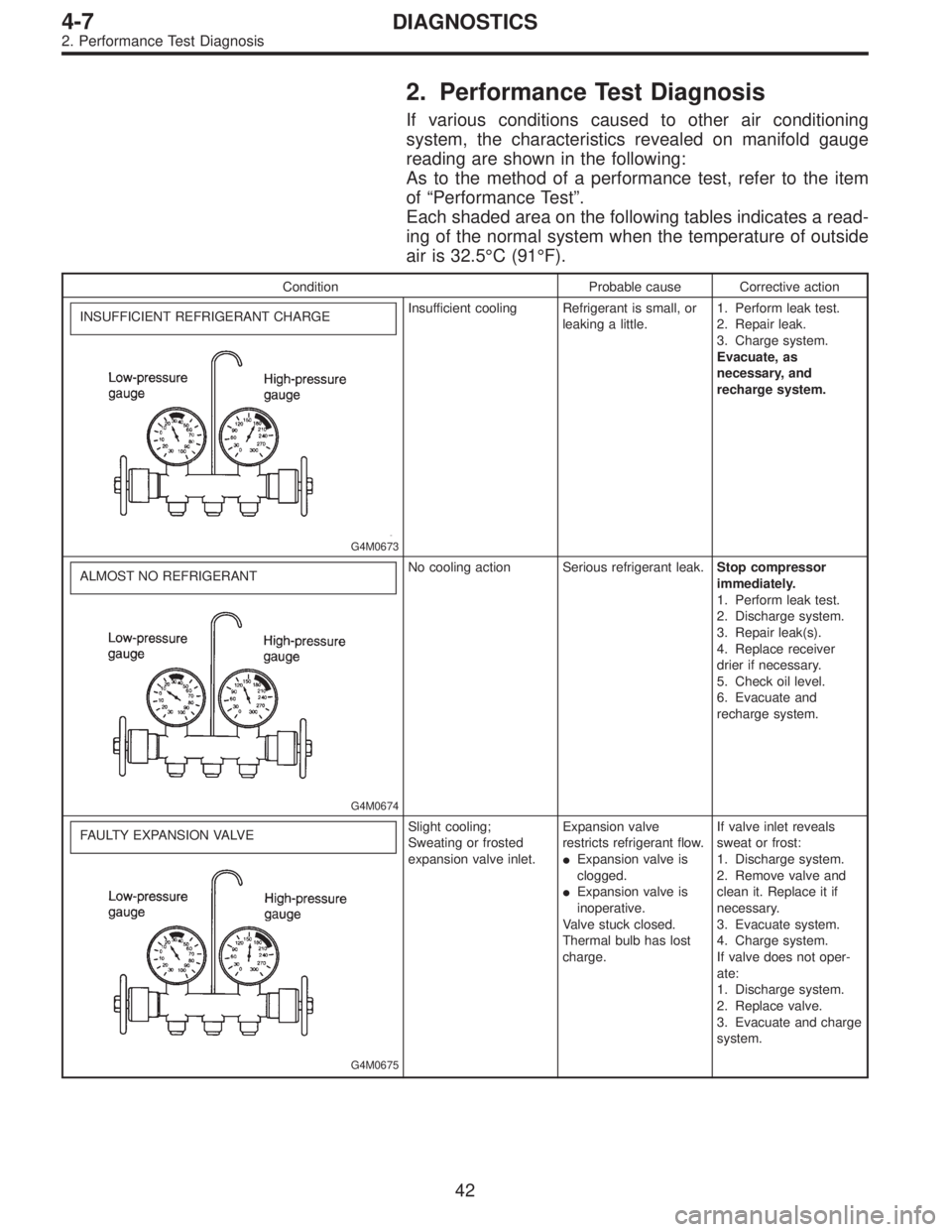
2. Performance Test Diagnosis
If various conditions caused to other air conditioning
system, the characteristics revealed on manifold gauge
reading are shown in the following:
As to the method of a performance test, refer to the item
of“Performance Test”.
Each shaded area on the following tables indicates a read-
ing of the normal system when the temperature of outside
air is 32.5°C (91°F).
Condition Probable cause Corrective action
INSUFFICIENT REFRIGERANT CHARGE
G4M0673
Insufficient cooling Refrigerant is small, or
leaking a little.1. Perform leak test.
2. Repair leak.
3. Charge system.
Evacuate, as
necessary, and
recharge system.
ALMOST NO REFRIGERANT
G4M0674
No cooling action Serious refrigerant leak.Stop compressor
immediately.
1. Perform leak test.
2. Discharge system.
3. Repair leak(s).
4. Replace receiver
drier if necessary.
5. Check oil level.
6. Evacuate and
recharge system.
FAULTY EXPANSION VALVE
G4M0675
Slight cooling;
Sweating or frosted
expansion valve inlet.Expansion valve
restricts refrigerant flow.
�Expansion valve is
clogged.
�Expansion valve is
inoperative.
Valve stuck closed.
Thermal bulb has lost
charge.If valve inlet reveals
sweat or frost:
1. Discharge system.
2. Remove valve and
clean it. Replace it if
necessary.
3. Evacuate system.
4. Charge system.
If valve does not oper-
ate:
1. Discharge system.
2. Replace valve.
3. Evacuate and charge
system.
42
4-7DIAGNOSTICS
2. Performance Test Diagnosis
Page 1421 of 2890
Condition Probable cause Corrective action
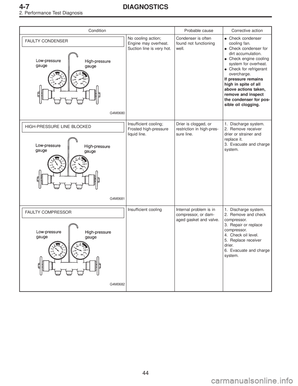
FAULTY CONDENSER
G4M0680
No cooling action;
Engine may overheat.
Suction line is very hot.Condenser is often
found not functioning
well.�Check condenser
cooling fan.
�Check condenser for
dirt accumulation.
�Check engine cooling
system for overheat.
�Check for refrigerant
overcharge.
If pressure remains
high in spite of all
above actions taken,
remove and inspect
the condenser for pos-
sible oil clogging.
HIGH-PRESSURE LINE BLOCKED
G4M0681
Insufficient cooling;
Frosted high-pressure
liquid line.Drier is clogged, or
restriction in high-pres-
sure line.1. Discharge system.
2. Remove receiver
drier or strainer and
replace it.
3. Evacuate and charge
system.
FAULTY COMPRESSOR
G4M0682
Insufficient cooling Internal problem is in
compressor, or dam-
aged gasket and valve.1. Discharge system.
2. Remove and check
compressor.
3. Repair or replace
compressor.
4. Check oil level.
5. Replace receiver
drier.
6. Evacuate and charge
system.
44
4-7DIAGNOSTICS
2. Performance Test Diagnosis
Page 1655 of 2890
1. Body Electrical
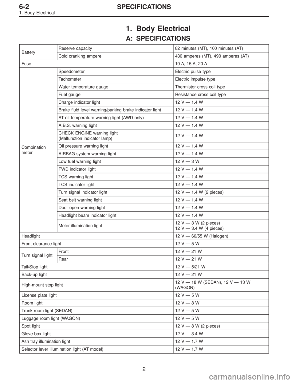
A: SPECIFICATIONS
BatteryReserve capacity 82 minutes (MT), 100 minutes (AT)
Cold cranking ampere 430 amperes (MT), 490 amperes (AT)
Fuse10 A, 15 A, 20 A
Combination
meterSpeedometer Electric pulse type
Tachometer Electric impulse type
Water temperature gauge Thermistor cross coil type
Fuel gauge Resistance cross coil type
Charge indicator light 12 V—1.4 W
Brake fluid level warning/parking brake indicator light 12 V—1.4 W
AT oil temperature warning light (AWD only) 12 V—1.4 W
A.B.S. warning light 12 V—1.4 W
CHECK ENGINE warning light
(Malfunction indicator lamp)12 V—1.4 W
Oil pressure warning light 12 V—1.4 W
AIRBAG system warning light 12 V—1.4 W
Low fuel warning light 12 V—3W
FWD indicator light 12 V—1.4 W
TCS warning light 12 V—1.4 W
TCS indicator light 12 V—1.4 W
Turn signal indicator light 12 V—1.4 W (2 pieces)
Seat belt warning light 12 V—1.4 W
Door open warning light 12 V—1.4 W
Headlight beam indicator light 12 V—1.4 W
Meter illumination light12 V—3 W (2 pieces)
12 V—3.4 W (4 pieces)
Headlight 12 V—60/55 W (Halogen)
Front clearance light 12 V—5W
Turn signal lightFront 12 V—21 W
Rear 12 V—21 W
Tail/Stop light 12 V—5/21 W
Back-up light 12 V—21 W
High-mount stop light12 V—18 W (SEDAN), 12 V—13 W
(WAGON)
License plate light 12 V—5W
Room light 12 V—8W
Trunk room light (SEDAN) 12 V—5W
Luggage room light (WAGON) 12 V—5W
Spot light 12 V—8 W (2 pieces)
Glove box light 12 V—3.4 W
Ash tray illumination light 12 V—1.7 W
Selector lever illumination light (AT model) 12 V—1.7 W
2
6-2SPECIFICATIONS
1. Body Electrical
Page 1695 of 2890
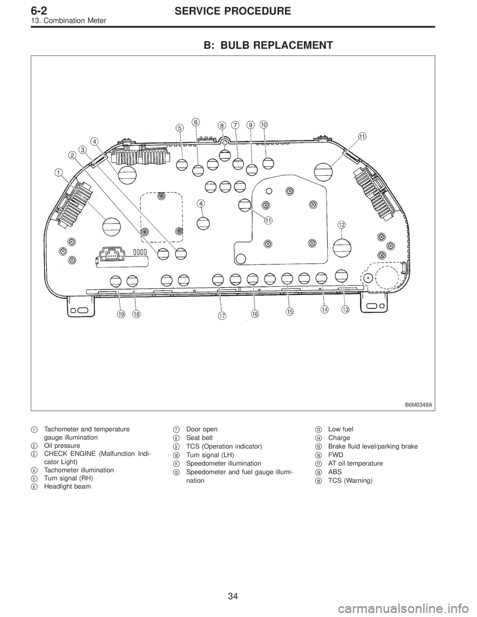
B: BULB REPLACEMENT
B6M0348A
�1Tachometer and temperature
gauge illumination
�
2Oil pressure
�
3CHECK ENGINE (Malfunction Indi-
cator Light)
�
4Tachometer illumination
�
5Turn signal (RH)
�
6Headlight beam�
7Door open
�
8Seat belt
�
9TCS (Operation indicator)
�
10Turn signal (LH)
�
11Speedometer illumination
�
12Speedometer and fuel gauge illumi-
nation�
13Low fuel
�
14Charge
�
15Brake fluid level/parking brake
�
16FWD
�
17AT oil temperature
�
18ABS
�
19TCS (Warning)
34
6-2SERVICE PROCEDURE
13. Combination Meter
Page 1775 of 2890
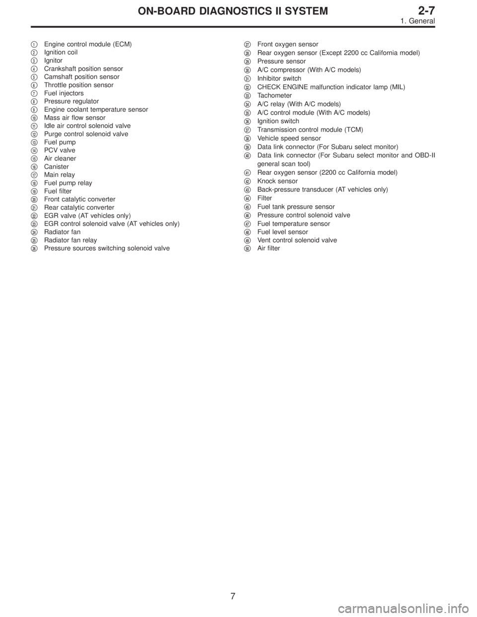
�1Engine control module (ECM)
�
2Ignition coil
�
3Ignitor
�
4Crankshaft position sensor
�
5Camshaft position sensor
�
6Throttle position sensor
�
7Fuel injectors
�
8Pressure regulator
�
9Engine coolant temperature sensor
�
10Mass air flow sensor
�
11Idle air control solenoid valve
�
12Purge control solenoid valve
�
13Fuel pump
�
14PCV valve
�
15Air cleaner
�
16Canister
�
17Main relay
�
18Fuel pump relay
�
19Fuel filter
�
20Front catalytic converter
�
21Rear catalytic converter
�
22EGR valve (AT vehicles only)
�
23EGR control solenoid valve (AT vehicles only)
�
24Radiator fan
�
25Radiator fan relay
�
26Pressure sources switching solenoid valve�
27Front oxygen sensor
�
28Rear oxygen sensor (Except 2200 cc California model)
�
29Pressure sensor
�
30A/C compressor (With A/C models)
�
31Inhibitor switch
�
32CHECK ENGINE malfunction indicator lamp (MIL)
�
33Tachometer
�
34A/C relay (With A/C models)
�
35A/C control module (With A/C models)
�
36Ignition switch
�
37Transmission control module (TCM)
�
38Vehicle speed sensor
�
39Data link connector (For Subaru select monitor)
�
40Data link connector (For Subaru select monitor and OBD-II
general scan tool)
�
41Rear oxygen sensor (2200 cc California model)
�
42Knock sensor
�
43Back-pressure transducer (AT vehicles only)
�
44Filter
�
45Fuel tank pressure sensor
�
46Pressure control solenoid valve
�
47Fuel temperature sensor
�
48Fuel level sensor
�
49Vent control solenoid valve
�
50Air filter
7
2-7ON-BOARD DIAGNOSTICS II SYSTEM
1. General
Page 1844 of 2890
1. BASIC CHECK ITEMS FOR AT
When trouble code about automatic transmission is shown
on display, carry out the following basic check. After that,
carry out the replacement or repair work.
1) ATF level check
2) Differential gear oil level check
3) ATF leak check
4) Differential gear oil leak check
5) Brake band adjustment
6) Stall test
7) Line pressure test
8) Transfer clutch pressure test
9) Time lag test
10) Road test
11) Shift characteristics
NOTE:
As for the method, refer to 3-2 [W2A0], [W2B1], [W300].
76
2-7ON-BOARD DIAGNOSTICS II SYSTEM
6. Basic Diagnostics Procedure
Page 1846 of 2890
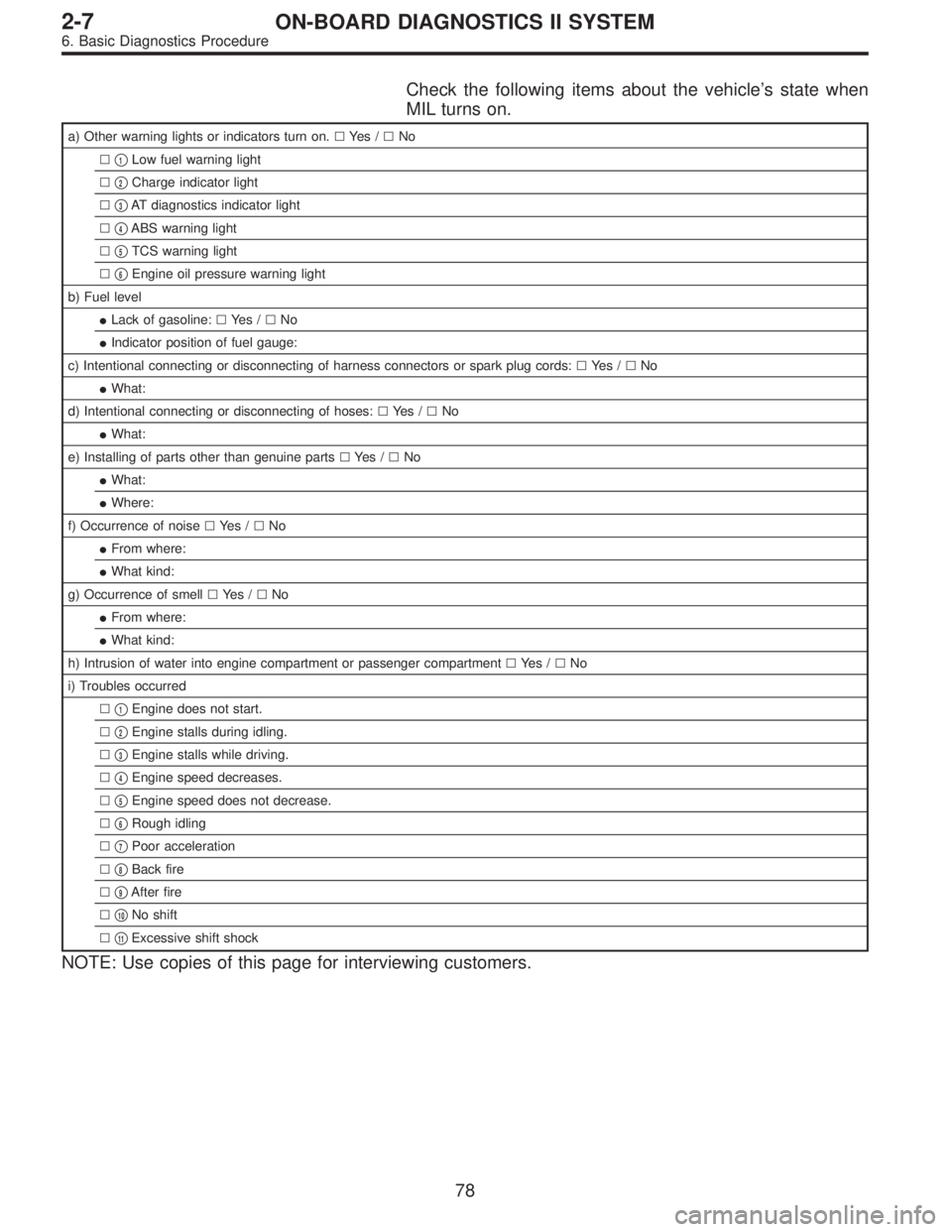
Check the following items about the vehicle’s state when
MIL turns on.
a) Other warning lights or indicators turn on.�Ye s /�No
��
1Low fuel warning light
��
2Charge indicator light
��
3AT diagnostics indicator light
��
4ABS warning light
��
5TCS warning light
��
6Engine oil pressure warning light
b) Fuel level
�Lack of gasoline:�Ye s /�No
�Indicator position of fuel gauge:
c) Intentional connecting or disconnecting of harness connectors or spark plug cords:�Ye s /�No
�What:
d) Intentional connecting or disconnecting of hoses:�Ye s /�No
�What:
e) Installing of parts other than genuine parts�Ye s /�No
�What:
�Where:
f) Occurrence of noise�Ye s /�No
�From where:
�What kind:
g) Occurrence of smell�Ye s /�No
�From where:
�What kind:
h) Intrusion of water into engine compartment or passenger compartment�Ye s /�No
i) Troubles occurred
��
1Engine does not start.
��
2Engine stalls during idling.
��
3Engine stalls while driving.
��
4Engine speed decreases.
��
5Engine speed does not decrease.
��
6Rough idling
��
7Poor acceleration
��
8Back fire
��
9After fire
��
10No shift
��
11Excessive shift shock
NOTE: Use copies of this page for interviewing customers.
78
2-7ON-BOARD DIAGNOSTICS II SYSTEM
6. Basic Diagnostics Procedure
Page 1888 of 2890

Overrunning clutch
Drive pinion
Crown gear
Axle shaft
Differential gear
Final gear
Seal pipe
Oil pump
High clutch
Band brake
Low & reverse clutch
Reverse clutch
One-way clutch (1-2)
One-way clutch (3-4)
Double oil seal
Input shaft
Output shaft
Planetary gear
Reduction gear
Drive plate
Torque converter one-way clutch
Lock-up facing
Lock-up damper
ATF deterioration
ATF level too high or too low
Differential gear oil level too high or too low
Engine performance
Engine speed signal
Parking brake mechanism
Problem parts
30 31 32 33 34 35 36 37 38 39 40 41 42 43 44 45 46 47 48 49 50 51 52 53 54 55 56 57 58 Symptom
Starter does not rotate when select lever is
in“P”or“N.”; starter rotates when select
lever is“R”,“D”,“3”or“2.”
���Abnormal noise when select lever is in“P”or
“N.”
�Hissing noise occurs during standing starts.
����Noise occurs while driving in“D
1”range.
����Noise occurs while driving in“D
2”range.
���Noise occurs while driving in“D
3”range.
����Noise occurs while driving in“D
4”range.
��Engine stalls while shifting from one range to
another.
Vehicle moves when select lever is in“N.”
�Shock occurs when select lever is moved
from“N”to“D.”
Excessive time lag occurs when select lever
is moved from“N”to“D.”
�Shock occurs when select lever is moved
from“N”to“R.”
��Excessive time lag occurs when select lever
is moved from“N”to“R.”
���� � ��� � �Vehicle does not start in any shift range
(engine revving up).
�Vehicle does not start in any shift range
(engine stall).
��Vehicle does not start in“R”range only
(engine revving up).
��Vehicle does not start in“R”range only
(engine stall).
�Vehicle does not start in“D”or“3”range
(engine revving up).
Vehicle does not start in“D”,“3”or“2”range
(engine revving up).
�Vehicle does not start in“D”,“3”or“2”range
(engine stall).
Vehicle starts in“R”range only (engine rev-
ving up).
��Acceleration during standing starts is poor
(high stall rpm).
���Acceleration during standing starts is poor
(low stall rpm).
�� �Acceleration is poor when select lever is in
“D”,“3”or“2”range (normal stall rpm).
����Acceleration is poor when select lever is in
“R”(normal stall rpm).
�No shift occurs from 1st to 2nd gear.
��No shift occurs from 2nd to 3rd gear.
�No shift occurs from 3rd to 4th gear.
No“kick-down”shifts occur.
Engine brake is not effected when select
lever is in“3”range.
30 31 32 33 34 35 36 37 38 39 40 41 42 43 44 45 46 47 48 49 50 51 52 53 54 55 56 57 58
120
2-7ON-BOARD DIAGNOSTICS II SYSTEM
9. General Diagnostics Table