Page 733 of 2890
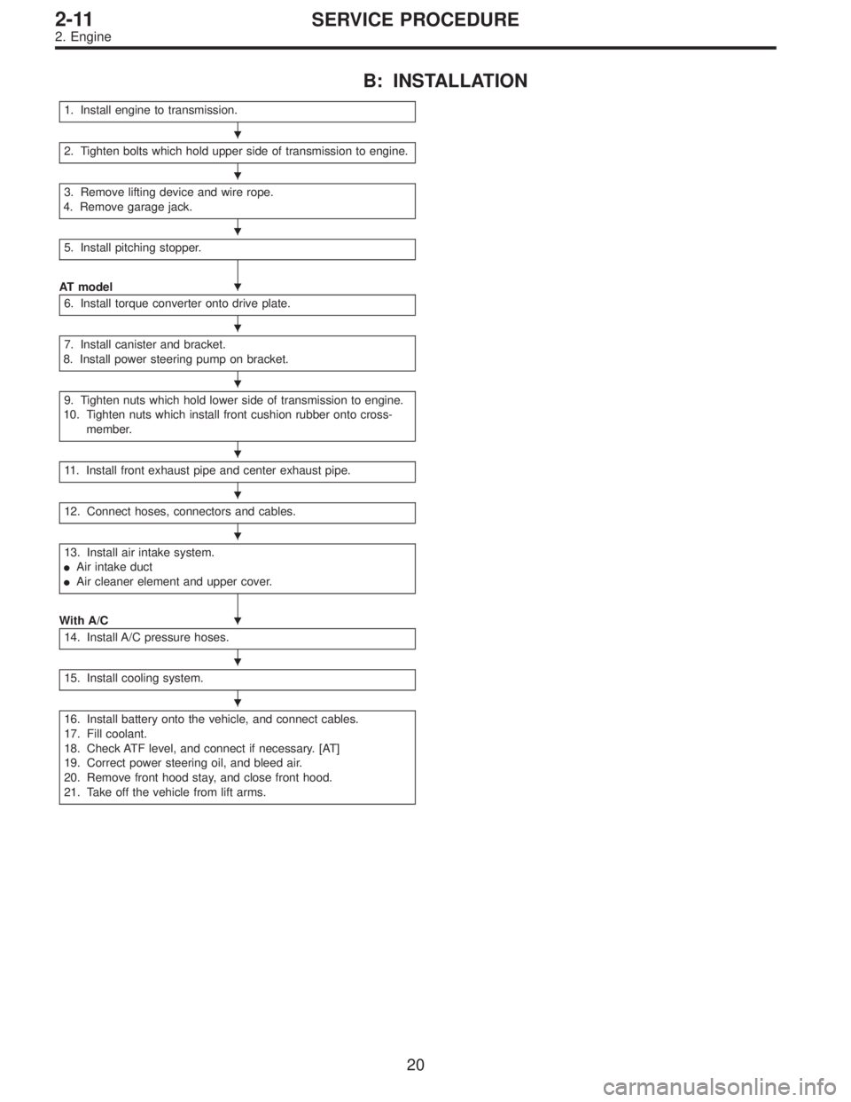
B: INSTALLATION
1. Install engine to transmission.
2. Tighten bolts which hold upper side of transmission to engine.
3. Remove lifting device and wire rope.
4. Remove garage jack.
5. Install pitching stopper.
AT model
6. Install torque converter onto drive plate.
7. Install canister and bracket.
8. Install power steering pump on bracket.
9. Tighten nuts which hold lower side of transmission to engine.
10. Tighten nuts which install front cushion rubber onto cross-
member.
11. Install front exhaust pipe and center exhaust pipe.
12. Connect hoses, connectors and cables.
13. Install air intake system.
�Air intake duct
�Air cleaner element and upper cover.
With A/C
14. Install A/C pressure hoses.
15. Install cooling system.
16. Install battery onto the vehicle, and connect cables.
17. Fill coolant.
18. Check ATF level, and connect if necessary. [AT]
19. Correct power steering oil, and bleed air.
20. Remove front hood stay, and close front hood.
21. Take off the vehicle from lift arms.
�
�
�
�
�
�
�
�
�
�
�
�
20
2-11SERVICE PROCEDURE
2. Engine
Page 746 of 2890
G2M0316
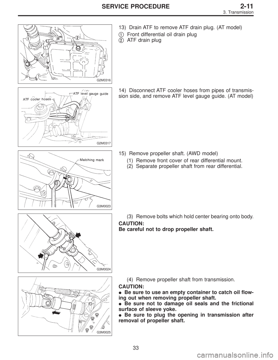
13) Drain ATF to remove ATF drain plug. (AT model)
�
1Front differential oil drain plug
�
2ATF drain plug
G2M0317
14) Disconnect ATF cooler hoses from pipes of transmis-
sion side, and remove ATF level gauge guide. (AT model)
G3M0023
15) Remove propeller shaft. (AWD model)
(1) Remove front cover of rear differential mount.
(2) Separate propeller shaft from rear differential.
G3M0024
(3) Remove bolts which hold center bearing onto body.
CAUTION:
Be careful not to drop propeller shaft.
G3M0025
(4) Remove propeller shaft from transmission.
CAUTION:
�Be sure to use an empty container to catch oil flow-
ing out when removing propeller shaft.
�Be sure not to damage oil seals and the frictional
surface of sleeve yoke.
�Be sure to plug the opening in transmission after
removal of propeller shaft.
33
2-11SERVICE PROCEDURE
3. Transmission
Page 764 of 2890
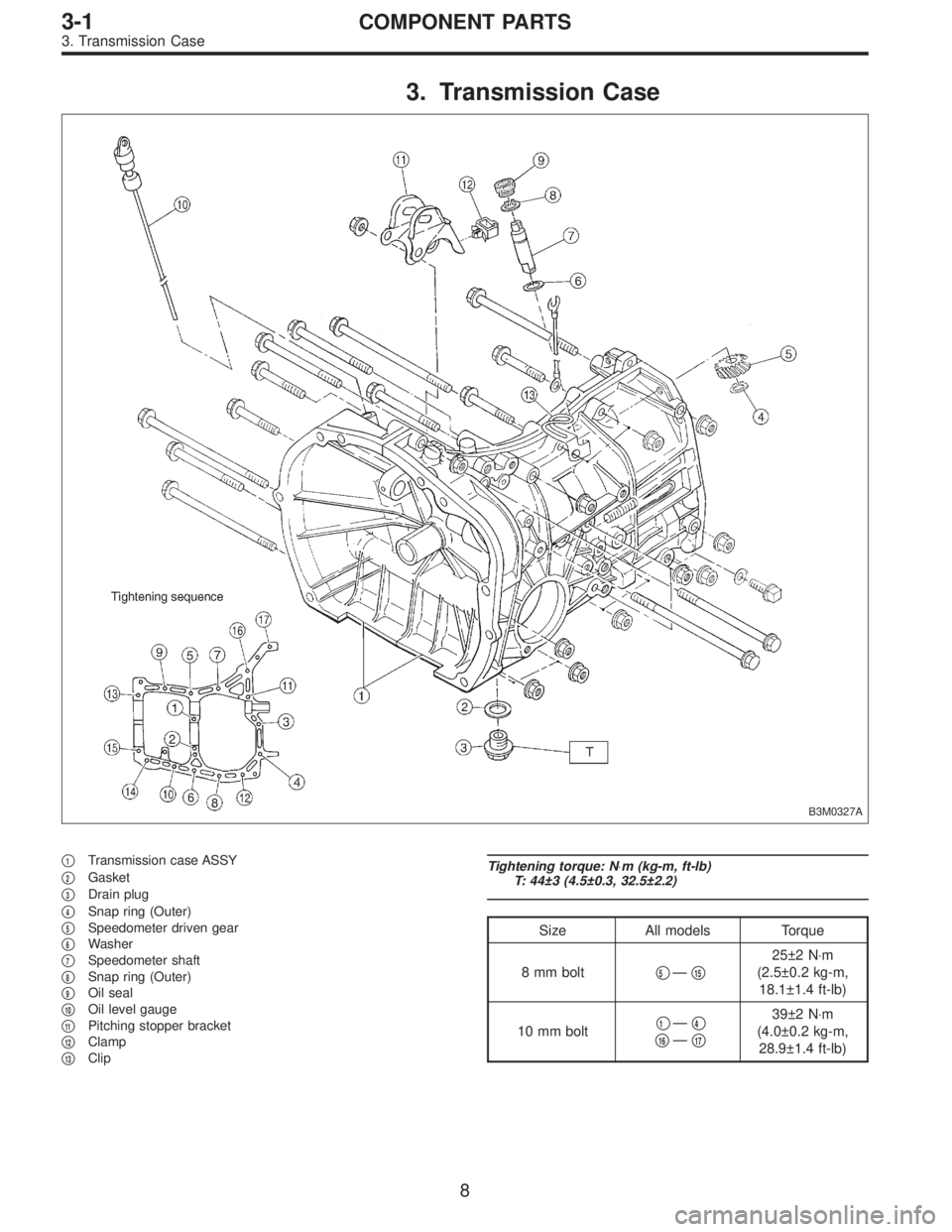
3. Transmission Case
B3M0327A
�1Transmission case ASSY
�
2Gasket
�
3Drain plug
�
4Snap ring (Outer)
�
5Speedometer driven gear
�
6Washer
�
7Speedometer shaft
�
8Snap ring (Outer)
�
9Oil seal
�
10Oil level gauge
�
11Pitching stopper bracket
�
12Clamp
�
13Clip
Tightening torque: N⋅m (kg-m, ft-lb)
T: 44±3 (4.5±0.3, 32.5±2.2)
Size All models Torque
8 mm bolt�
5—�15
25±2 N⋅m
(2.5±0.2 kg-m,
18.1±1.4 ft-lb)
10 mm bolt�
1—�4
�16—�17
39±2 N⋅m
(4.0±0.2 kg-m,
28.9±1.4 ft-lb)
8
3-1COMPONENT PARTS
3. Transmission Case
Page 772 of 2890
B3M0037A
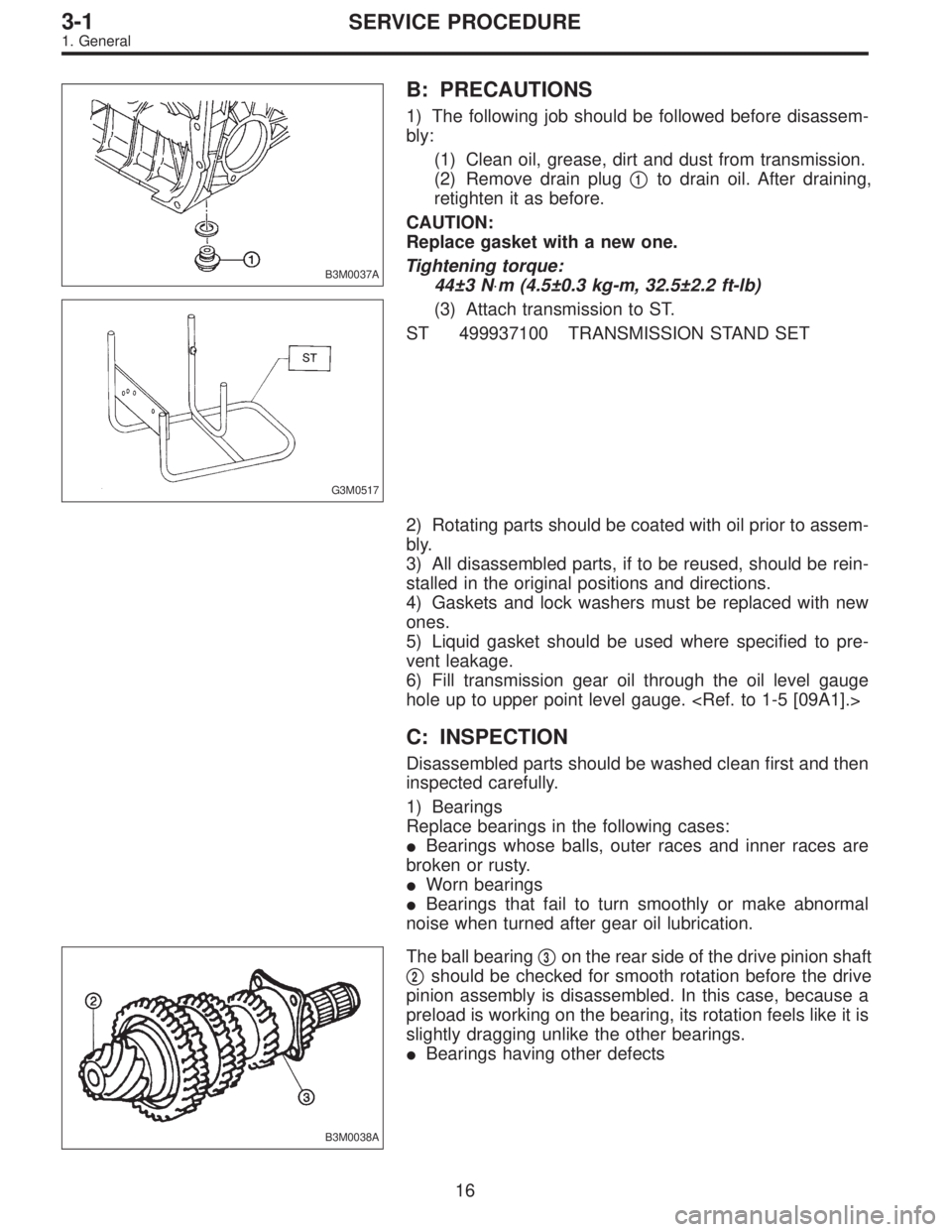
B: PRECAUTIONS
1) The following job should be followed before disassem-
bly:
(1) Clean oil, grease, dirt and dust from transmission.
(2) Remove drain plug�
1to drain oil. After draining,
retighten it as before.
CAUTION:
Replace gasket with a new one.
Tightening torque:
44±3 N⋅m (4.5±0.3 kg-m, 32.5±2.2 ft-lb)
G3M0517
(3) Attach transmission to ST.
ST 499937100 TRANSMISSION STAND SET
2) Rotating parts should be coated with oil prior to assem-
bly.
3) All disassembled parts, if to be reused, should be rein-
stalled in the original positions and directions.
4) Gaskets and lock washers must be replaced with new
ones.
5) Liquid gasket should be used where specified to pre-
vent leakage.
6) Fill transmission gear oil through the oil level gauge
hole up to upper point level gauge.
C: INSPECTION
Disassembled parts should be washed clean first and then
inspected carefully.
1) Bearings
Replace bearings in the following cases:
�Bearings whose balls, outer races and inner races are
broken or rusty.
�Worn bearings
�Bearings that fail to turn smoothly or make abnormal
noise when turned after gear oil lubrication.
B3M0038A
The ball bearing�3on the rear side of the drive pinion shaft
�
2should be checked for smooth rotation before the drive
pinion assembly is disassembled. In this case, because a
preload is working on the bearing, its rotation feels like it is
slightly dragging unlike the other bearings.
�Bearings having other defects
16
3-1SERVICE PROCEDURE
1. General
Page 826 of 2890
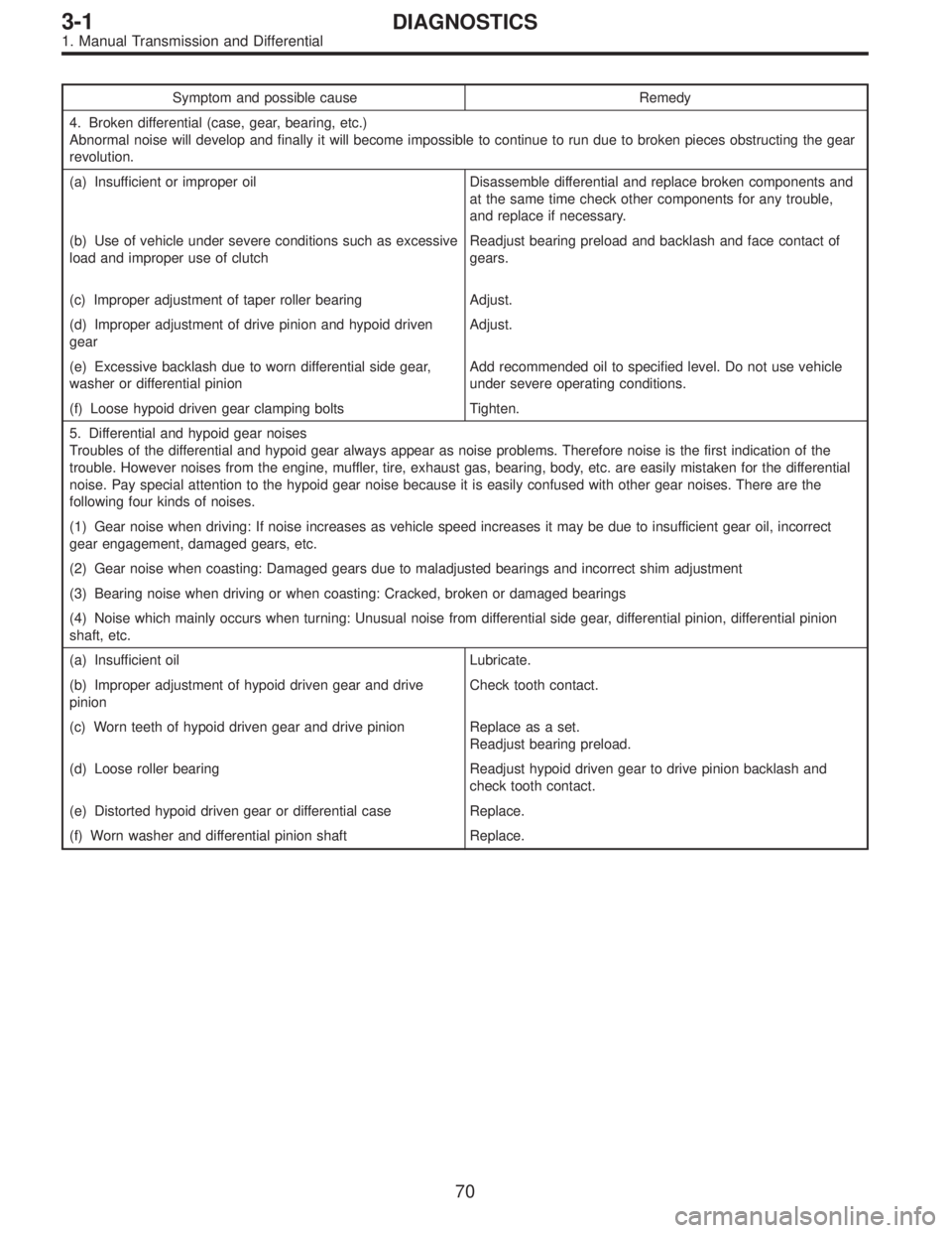
Symptom and possible cause Remedy
4. Broken differential (case, gear, bearing, etc.)
Abnormal noise will develop and finally it will become impossible to continue to run due to broken pieces obstructing the gear
revolution.
(a) Insufficient or improper oil Disassemble differential and replace broken components and
at the same time check other components for any trouble,
and replace if necessary.
(b) Use of vehicle under severe conditions such as excessive
load and improper use of clutchReadjust bearing preload and backlash and face contact of
gears.
(c) Improper adjustment of taper roller bearing Adjust.
(d) Improper adjustment of drive pinion and hypoid driven
gearAdjust.
(e) Excessive backlash due to worn differential side gear,
washer or differential pinionAdd recommended oil to specified level. Do not use vehicle
under severe operating conditions.
(f) Loose hypoid driven gear clamping bolts Tighten.
5. Differential and hypoid gear noises
Troubles of the differential and hypoid gear always appear as noise problems. Therefore noise is the first indication of the
trouble. However noises from the engine, muffler, tire, exhaust gas, bearing, body, etc. are easily mistaken for the differential
noise. Pay special attention to the hypoid gear noise because it is easily confused with other gear noises. There are the
following four kinds of noises.
(1) Gear noise when driving: If noise increases as vehicle speed increases it may be due to insufficient gear oil, incorrect
gear engagement, damaged gears, etc.
(2) Gear noise when coasting: Damaged gears due to maladjusted bearings and incorrect shim adjustment
(3) Bearing noise when driving or when coasting: Cracked, broken or damaged bearings
(4) Noise which mainly occurs when turning: Unusual noise from differential side gear, differential pinion, differential pinion
shaft, etc.
(a) Insufficient oil Lubricate.
(b) Improper adjustment of hypoid driven gear and drive
pinionCheck tooth contact.
(c) Worn teeth of hypoid driven gear and drive pinion Replace as a set.
Readjust bearing preload.
(d) Loose roller bearing Readjust hypoid driven gear to drive pinion backlash and
check tooth contact.
(e) Distorted hypoid driven gear or differential case Replace.
(f) Worn washer and differential pinion shaft Replace.
70
3-1DIAGNOSTICS
1. Manual Transmission and Differential
Page 836 of 2890
1. Torque Converter Clutch and Case
B3M0104A
�1Pitching stopper bracket
�
2Oil level gauge
�
3O-ring
�
4Oil seal
�
5Snap ring
�
6Washer
�
7Speedometer shaft
�
8Clip
�
9Oil pump shaft
�
10Seal ring
�
11Seal pipe
�
12Speedometer driven gear
�
13Snap ring
�
14Drain plug�
15Oil seal
�
16Harness clip
�
17Torque converter clutch case
�
18Torque converter clutch
�
19O-ring
�
20Input shaft
�
21Gasket
�
22Oil drain pipe
Tightening torque: N⋅m (kg-m, ft-lb)
T1: 18±5 (1.8±0.5, 13.0±3.6)
T2: 41±3 (4.2±0.3, 30.4±2.2)
T3: 44±3 (4.5±0.3, 32.5±2.2)
10
3-2COMPONENT PARTS
1. Torque Converter Clutch and Case
Page 841 of 2890
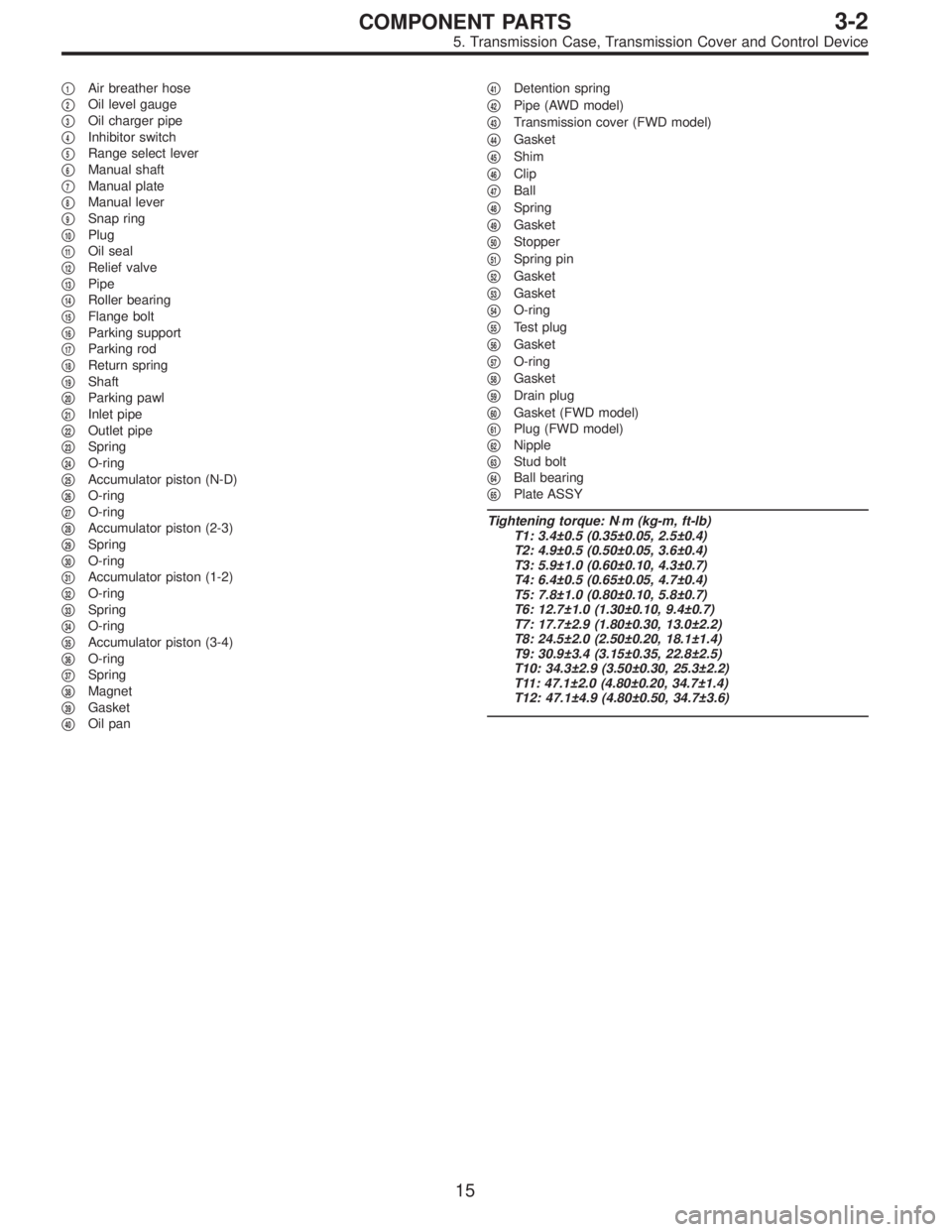
�1Air breather hose
�
2Oil level gauge
�
3Oil charger pipe
�
4Inhibitor switch
�
5Range select lever
�
6Manual shaft
�
7Manual plate
�
8Manual lever
�
9Snap ring
�
10Plug
�
11Oil seal
�
12Relief valve
�
13Pipe
�
14Roller bearing
�
15Flange bolt
�
16Parking support
�
17Parking rod
�
18Return spring
�
19Shaft
�
20Parking pawl
�
21Inlet pipe
�
22Outlet pipe
�
23Spring
�
24O-ring
�
25Accumulator piston (N-D)
�
26O-ring
�
27O-ring
�
28Accumulator piston (2-3)
�
29Spring
�
30O-ring
�
31Accumulator piston (1-2)
�
32O-ring
�
33Spring
�
34O-ring
�
35Accumulator piston (3-4)
�
36O-ring
�
37Spring
�
38Magnet
�
39Gasket
�
40Oil pan�
41Detention spring
�
42Pipe (AWD model)
�
43Transmission cover (FWD model)
�
44Gasket
�
45Shim
�
46Clip
�
47Ball
�
48Spring
�
49Gasket
�
50Stopper
�
51Spring pin
�
52Gasket
�
53Gasket
�
54O-ring
�
55Test plug
�
56Gasket
�
57O-ring
�
58Gasket
�
59Drain plug
�
60Gasket (FWD model)
�
61Plug (FWD model)
�
62Nipple
�
63Stud bolt
�
64Ball bearing
�
65Plate ASSY
Tightening torque: N⋅m (kg-m, ft-lb)
T1: 3.4±0.5 (0.35±0.05, 2.5±0.4)
T2: 4.9±0.5 (0.50±0.05, 3.6±0.4)
T3: 5.9±1.0 (0.60±0.10, 4.3±0.7)
T4: 6.4±0.5 (0.65±0.05, 4.7±0.4)
T5: 7.8±1.0 (0.80±0.10, 5.8±0.7)
T6: 12.7±1.0 (1.30±0.10, 9.4±0.7)
T7: 17.7±2.9 (1.80±0.30, 13.0±2.2)
T8: 24.5±2.0 (2.50±0.20, 18.1±1.4)
T9: 30.9±3.4 (3.15±0.35, 22.8±2.5)
T10: 34.3±2.9 (3.50±0.30, 25.3±2.2)
T11: 47.1±2.0 (4.80±0.20, 34.7±1.4)
T12: 47.1±4.9 (4.80±0.50, 34.7±3.6)
15
3-2COMPONENT PARTS
5. Transmission Case, Transmission Cover and Control Device
Page 847 of 2890

G3M0854
1. Precaution
When disassembling or assembling the automatic
transmission, observe the following instructions.
1) Workshop
Provide a place that is clean and free from dust. Principally
the conventional workshop is suitable except for a dusty
place. In a workshop where grinding work, etc. which pro-
duces fine particles is done, make independent place
divided by the vinyl curtain or the equivalent.
2) Work table
The size of 1 x 1.5 m (40 x 60 in) is large enough to work,
and it is more desirable that its surface be covered with flat
plate like iron plate which is not rusted too much.
3) Cleaning of exterior
(1) Clean the exterior surface of transmission with
steam and/or kerosene prior to disassembly, however it
should be noted that vinyl tape be placed on the air
breather or oil level gauge to prevent infiltration of the
steam into the transmission and also the cleaning job
be done away from the place of disassembly and
assembly.
(2) Partial cleaning will do, depending on the extent of
disassembly (such as when disassembly is limited to
some certain parts).
4) Disassembly, assembly and cleaning
(1) Disassemble and assemble the transmission while
inspecting the parts in accordance with the Diagnostics.
(2) During job, don’t use gloves. Don’t clean the parts
with rags: Use chamois or nylon cloth.
(3) Pay special attention to the air to be used for clean-
ing. Get the moisture and the dust rid of the air as much
as possible. Be careful not to scratch or dent any part
while checking for proper operation with an air gun.
(4) Complete the job from cleaning to completion of
assembly as continuously and speedily as possible in
order to avoid occurrence of secondary troubles
caused by dust. When stopping the job unavoidably
cover the parts with clean chamois or nylon cloth to
keep them away from any dust.
(5) Use kerosene, white gasoline or the equivalent as
washing fluid. Use always new fluid for cleaning the
automatic transmission parts and never reuse. The
used fluid is usable in disassemble and assemble work
of engine and manual transmission.
(6) Although the cleaning should be done by dipping
into the washing fluid or blowing of the pressurized
washing fluid, the dipping is more desirable. (Do not rub
with a brush.) Assemble the parts immediately after the
cleaning without exposure to the air for a while. Besides
in case of washing rubber parts, perform the job quickly
not to dip them into the washing fluid for long time.
21
3-2SERVICE PROCEDURE
1. Precaution